
Product Description
Product Description
In order to make the installation and configuration easier, we have developed this intelligent 1 button learning sliding door control board. The control board adopts advanced microcomputer chip, digital control, more practical functions, higher safety performance, easier installation and configuration. Fully compatible with the smartphone app network (WiFi/3G/4G/5G) control and bluetooth control and many other features.
Features
1. Anti-rush design.
At the first operation after each power on, the motor runs in slow motion to the limit point throughout the process to avoid rushing out of the limit. When the door reaches the limit point, the motor can only be operated by pressing the button of the opposite direction to prevent the limit from being broken out. (Notice: It has the power off protection function when in place, and the motor only moves in the opposite direction when repowered).
2. Master-slave mode available.
Two motors with the same control board on each can work synchronously. In this mode, infrared, ground sense, automatic door close and other functions are synchronized. Attention: Infrared, ground sense must be connected to the master motor.
3. Motor runtime protection.
To prevent the motor from running during the travel failure, the control board will automatically learn the motor running time without manual setting, and 10s will be added automatically as the time margin.
4. Auto-close function.
Time can be set from 1s to 250s before the door closes automatically. The default value is 3s.
5. Soft start and slow stop.
There’re soft start and slow stop features available. The distance and speed of the slow stop feature can be adjusted.
6. Stop & rebound against resistance.
Switchable between stop against resistance and rebound against resistance for the closing travel. Stop against resistance for the opening travle.
7. Onboard socket for bluetooth module.
A socket is integrated onboard for the insertion of the standalone bluetooth module (module not included by default).
8. One button configuration for internet control.
Can be directly paired with the internet controllers through pressing 1 button onboard, no copy procedure is required.
Product Parameters
| Working voltage: | AC220V/110V ± 10% input, DC 24V output. |
| Maximum Output Current: | 10A |
| Fuse: | AC220V 20A. |
| Remote control distance: | Over 30 CHINAMFG in open area |
| Ambient temperature range: | -25°~+75°. |
| Relative humidity: | <60%, NO CONDENSATION. |
Diagram
Configuration IntroductionDip Switch1: Remote Control One-key and Four-key Modes Switch
OFF position
Remote control with 4 independent keys functioning as Open, Close, Stop, Lock.When in the non-passageway mode, after pressing the Lock key, the Stop key needs to be pressed in prior to being able to operate.
ON position
(1) A single key on the remote is the one-key control key (The specific key pressed while pairing).
(2) Each key on the remote is a one-key control key.
Function setting
Turn and only turn 1 and 6 to ON, press SET once with a buzzer is the single key one-key mode, press again with 4 buzzers is the 4 keys one-key mode. Turn 6 to OFF after setting.
Dip Switch 2: Passageway Mode OFF PositionDisable the passageway mode. ON PositionEnable the passageway mode (1 at OFF, 2 at ON).
When the gate is closed at the limit position, press the Lock key will make the motor run in the opening motion for 6s.
Dip Switch 3: Auto-close OFF PositionDisable the auto-close function.
ON Position
Enable the auto-close funciton. Only when the gate is opened at the limit position will the countdown starts, then the gate will automatically close to the limit position.
Auto-close timer setting
Turn and only turn 3 and 6 to ON, each press on the SET key is 1s, set it as long as you
wish up to 250s. After setting, turn 6 to OFF.
Dip Switch 4: Slow Stop OFF PositionDisable the slow stop function. ON PositionEnable the slow stop function (Effective only after travel distance learning).
The speed of Slow Stop can be adjusted with the MT adjustor, turn it clockwise to gain the speed, turn it anti-clockwise to reduce the speed.
The distance of Slow Stop can be adjusted with the TIME adjustor, turn it clockwise to gain the distance, turn it anti-clockwise to reduce the distance.
Travel Distance Learning
Turn and only turn 4 and 6 to ON, then hold down the ONE key until the gate starts running auomatically and release. It will close to the limit and open to the limit, and close to the limit again with the slow stop effect. After 2 beeps, the travel distance learning procedure is complete.
Dip Switch 5: Startup Strength
OFF Position
Enable the slow start function. The gate runs at a slower speed for the first 2s, to reduce the tremble of the gate.
ON PositionMax start speed. The gate runs at the maximum speed from the very beginning.Dip Switch 6: Setting Key OFF PositionMake the settings take effect.
ON Position
Enable the setting mode for the One-key function, Auto-close function and Slow Stopfunctions. When the settings are set, turn this key to OFF to take effect.
Dip Switch 7: Resistance Stop & Rebound OFF PositionThe gate stops when running to either open or close.
ON Position
The gate stops against resistance when running to open. When running to close, the gate stops against resistance for 1s and then rebound.
Optimized resistance rebound adjustment
Make sure the motor functions properly. Turn on dip switch 7, then while the motor is in the motion of closing, rotate the FORCE adjustor anticlockwise to allow the door stops and return automatically, this is the threshold of the resistance force, it’s suggested to rotate the adjustor clockwise a little bit to set it as the final resistance force.
Dip Switch 8: Motor Rotation Direction Swap Swap this switch to reverse the rotation direction of the gear.Blue Dip Switch 1: Normally Closed/Open OFF PositionSet the motor status to normally open. ON PositionSet the motor status to normally closed.Blue Dip Switch 2: Master-slave Mode OFF PostionSet the current motor as the master motor. ON PositionSet the current motor as the slave motor.
Master-slave mode means 2 motors with the same control board installed on each work synchronously when the master motor is being operated. Connect 2 motors through the 485A+Binterfaces on both motors in parallel to realize the master-slave mode.
Remote Control Paring And DeletionPairing
Hold down the STUDY button on the control board for about 1s until a buzz, then hold down any key of the remote control, release it against a buzz, and the pairing procedure is complete. Repeat this step to pair more remotes. Up to 120 remotes can be paired with a single board.
Deletion
Hold down the STUDY button on the control board for about 7s, release it against 3 continuous buzzesto delete all paired remotes.
P.S.: After entering the pairing state, if no effective RF signal is sensed, the board will exit the pairing state automatically with a buzz and the LED returning to always on.
Gatelink Roling Code Learning Method
▪ Remote Without Locked Type (Button No Function).
▪ Press and hold the “Learn/Delete” button on the GateLink receiving board for about 1 second,the indicator will turn off,can hear the buzzer give a “didi”sound,to remind the user release the button,and then enter into remote learning type, press and hold the remote transponder any button(open/close/stop),release it after heard the buzzer give”didi”sound again,learning finished.
Remote With Locked Type (Button With Function)
▪ Press and hold the “Learn/Delete” button on the GateLink receiving board for about 1 second,the indicator will turn off,can hear the buzzer give a “didi”sound,to remind the user release the button,and then enter into remote learning type,press and hold the “Lock” button, release it after heard the buzzer give”didi”sound again,learning finished;
▪ If choosed the wrong mode, you can re-learn again. Repeat this step to learn multiple remote transponder, and the regular version can store up to 64 GateLink ID; (256 Gatelink ID can be optional also).
UNDER-V Indicator
1. When the voltage of the battery is in between 19 ~ 20V, the UNDER-V indicator is always on.2. When the voltage of the battery is lower than 19V, the UNDER-V indicator flashes constantly, the board enters the under-voltage state and will not carry out the motions of neither opening nor closing.BLE Indicator
1. When the bluetooth module is not bound, the BLE indicator flashes once per second constantly.
2. After binding, the BLE indicator flashes once per second when linked with the mobile app, and goes off when the app is quit.3. After holding down the BLE key for 5s to reset the bluetooth feature, the BLE indicator will stay on.Charge Indicator
1. When charging, the red LED is always on.
2. The red LED goes off after full charged.
Photocell Indicator
When triggered, the corresponding red LED is on, otherwise it stays off.
Stop Indicator
When triggered, the corresponding red LED is on, otherwise it stays off.
Manual Button Indicator
When triggered, the corresponding red LED is on, otherwise it stays off.
Closing Indicator
When triggered, the corresponding yellow LED is on, otherwise it stays off.
Opening Indicator
When triggered, the corresponding green LED is on, otherwise it stays off.
Loop Indicator
When triggered, the corresponding red LED is on, otherwise it stays off.
Closed Limiter Indicator
When the gate is closed at the limit position, the corresponding LED stays on, otherwise it’s off.
Open Limiter Indicator
When the gate is open at the limit position, the corresponding LED stays on, otherwise it’s off.
Buzzer Introduction
1. A buzz occurs each time a dip switch is dipped.
2. When in the unlocked status under the Lock mode, a buzz occurs when the LOCK button on the remote is pressed indicating the remote is locked. When in the locked statuse, press the STOP button on the remote causes 2 buzzes, and the remote is unlocked.
3. When both limit swithes are triggered at the same time, the buzzer keeps buzzing and the motor cannot be operated by any button, in this case the height of the magnet should be adjusted.
4. When the gate is at the open/closed limit position, if the open/close button on the remote is pressed, 3 continuous buzzes occur and no reaction happens.
5. Stop against resistance when opening will cause 3 continuous buzzes, stop/rebound against resistance when closing will cause 5 continuous buzzes.
Magnetic Limit Switch Installation Xihu (West Lake) Dis.
Move the gate to the ideal closed position, fix the magnet on the gear rack at the spot where the limit switch box is located and make sure the magnet is facing to the box. Do the same with another magnet for the open position at the other end of the racks. Make sure the magnet on the left is higher and the 1 on the right is lower. When at a certain limit position, the corresponding LED indicator on the board will stays on. If the 2 indicators are on at the same time along with a constant buzz, the height of the magnet needs to be adjusted.
M-S Mode (Double Machines Synchronized) Setup Xihu (West Lake) Dis.Connection
1. Turn the Master/Slave dip switch to ON on the master motor. Leave the switch at OFF on the slave motor.
2. Connect the A+ B- interfaces on the master motor to the corresponding interfaces on the slave motor.
After connecting, if the RUN indicators on both master and slave motors flashes synchronouly once per second, it’s properly set. Otherwise, check the wire connection or the status of the dip switches.Functions1. When the M-S mode is successfully set, the remotes paired with the slave motor and the Manual button, Study/Delete button on the slave motor are all out of function as well as the Open, Stop, Close functions of any external control devices connected with the slave motor.2. When operating the remotes paired with the master motor, and the Manual button, Study/Delete button on the master motor as well as the Open, Stop, Close functions of any external control devicesconnected with the master motor, the slave motor will carry out the same operations.3. The resistance stop/rebound function, photocell function, loop function on both motors can be triggered from either motor and carry out the corresponding function on the other at the same time.4. The auto-close function of the slave motor is overwritten by the master motor, if this function is supposed to be used, turn the AUTO CLOSE dip switch to ON on the master motor.5. The low speed rate and resistance force can be set on each motor separately.6. The limit function on each motor works separately, it is to be set on either motor before linking.
/* January 22, 2571 19:08:37 */!function(){function s(e,r){var a,o={};try{e&&e.split(“,”).forEach(function(e,t){e&&(a=e.match(/(.*?):(.*)$/))&&1
| After-sales Service: | Online Technical Training |
|---|---|
| Warranty: | 2 Years |
| Structure: | Wheeled |
| Samples: |
US$ 240/Piece
1 Piece(Min.Order) | Order Sample |
|---|
| Customization: |
Available
|
|
|---|
.shipping-cost-tm .tm-status-off{background: none;padding:0;color: #1470cc}
|
Shipping Cost:
Estimated freight per unit. |
about shipping cost and estimated delivery time. |
|---|
| Payment Method: |
|
|---|---|
|
Initial Payment Full Payment |
| Currency: | US$ |
|---|
| Return&refunds: | You can apply for a refund up to 30 days after receipt of the products. |
|---|
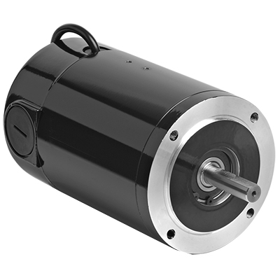
How does the speed control of a DC motor work, and what methods are commonly employed?
The speed control of a DC (Direct Current) motor is essential for achieving precise control over its rotational speed. Various methods can be employed to regulate the speed of a DC motor, depending on the specific application requirements. Here’s a detailed explanation of how speed control of a DC motor works and the commonly employed methods:
1. Voltage Control:
One of the simplest methods to control the speed of a DC motor is by varying the applied voltage. By adjusting the voltage supplied to the motor, the electromotive force (EMF) induced in the armature windings can be controlled. According to the principle of electromagnetic induction, the speed of the motor is inversely proportional to the applied voltage. Therefore, reducing the voltage decreases the speed, while increasing the voltage increases the speed. This method is commonly used in applications where a simple and inexpensive speed control mechanism is required.
2. Armature Resistance Control:
Another method to control the speed of a DC motor is by varying the armature resistance. By inserting an external resistance in series with the armature windings, the total resistance in the circuit increases. This increase in resistance reduces the armature current, thereby reducing the motor’s speed. Conversely, reducing the resistance increases the armature current and the motor’s speed. However, this method results in significant power loss and reduced motor efficiency due to the dissipation of excess energy as heat in the external resistance.
3. Field Flux Control:
Speed control can also be achieved by controlling the magnetic field strength of the motor’s stator. By altering the field flux, the interaction between the armature current and the magnetic field changes, affecting the motor’s speed. This method can be accomplished by adjusting the field current through the field windings using a field rheostat or by employing a separate power supply for the field windings. By increasing or decreasing the field flux, the speed of the motor can be adjusted accordingly. This method offers good speed regulation and efficiency but requires additional control circuitry.
4. Pulse Width Modulation (PWM):
Pulse Width Modulation is a widely used technique for speed control in DC motors. It involves rapidly switching the applied voltage on and off at a high frequency. The duty cycle, which represents the percentage of time the voltage is on, is varied to control the effective voltage applied to the motor. By adjusting the duty cycle, the average voltage across the motor is modified, thereby controlling its speed. PWM provides precise speed control, high efficiency, and low power dissipation. It is commonly employed in applications such as robotics, industrial automation, and electric vehicles.
5. Closed-Loop Control:
In closed-loop control systems, feedback from the motor’s speed or other relevant parameters is used to regulate the speed. Sensors such as encoders or tachometers measure the motor’s actual speed, which is compared to the desired speed. The difference, known as the error signal, is fed into a control algorithm that adjusts the motor’s input voltage or other control parameters to minimize the error and maintain the desired speed. Closed-loop control provides excellent speed regulation and accuracy, making it suitable for applications that require precise speed control, such as robotics and CNC machines.
These methods of speed control provide flexibility and adaptability to various applications, allowing DC motors to be effectively utilized in a wide range of industries and systems.
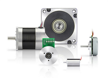
What is the significance of back EMF (electromotive force) in DC motor performance?
The significance of back EMF (electromotive force) in DC motor performance is crucial to understanding the behavior and operation of DC motors. Back EMF is an inherent characteristic of DC motors and plays a pivotal role in their efficiency, speed regulation, and overall performance. Here’s a detailed explanation of the significance of back EMF in DC motor performance:
When a DC motor operates, it generates a voltage known as back EMF or counter electromotive force. This voltage opposes the applied voltage and is caused by the rotation of the motor’s armature within the magnetic field. The back EMF is directly proportional to the rotational speed of the motor.
The significance of back EMF can be understood through the following aspects:
1. Speed Regulation:
Back EMF is crucial for regulating the speed of a DC motor. As the motor rotates faster, the back EMF increases, which reduces the effective voltage across the motor’s armature. Consequently, the armature current decreases, limiting the motor’s speed. This self-regulating characteristic helps maintain a relatively constant speed under varying load conditions. It allows the motor to deliver the required torque while preventing excessive speed that can potentially damage the motor or the driven equipment.
2. Efficiency:
Back EMF plays a significant role in the efficiency of a DC motor. When the motor is loaded and drawing current, the power supplied to the motor is the product of the armature current and the applied voltage. However, the electrical power converted into mechanical power is reduced by the power consumed by the back EMF. The back EMF represents the energy returned to the power supply as the motor generates its own voltage. By reducing the effective voltage across the motor, it helps minimize power losses due to electrical resistance and improves the overall efficiency of the motor.
3. Motor Protection:
The presence of back EMF also provides a level of protection to the motor. When a DC motor is operating and the load on the motor suddenly decreases, such as when the driven equipment is disconnected, the motor’s speed can increase rapidly. This increase in speed leads to a higher back EMF, which reduces the armature current and prevents excessive current flow. By limiting the current, the back EMF helps protect the motor from overloading and potential damage.
4. Voltage Regulation:
Back EMF affects the voltage regulation in a DC motor. When the motor is operating, the back EMF opposes the applied voltage. As the motor load increases, the voltage drop across the armature resistance and other internal losses also increase. The back EMF helps compensate for these voltage drops, ensuring that the motor receives an adequate voltage to maintain its performance and torque output.
5. Control and Dynamic Response:
Back EMF provides valuable information for motor control and dynamic response. By measuring the back EMF voltage, the rotational speed of the motor can be estimated, allowing for precise speed control and feedback. This information is crucial for applications that require accurate speed regulation, such as robotics or industrial automation.
In summary, the significance of back EMF in DC motor performance cannot be overstated. It influences speed regulation, efficiency, motor protection, voltage regulation, and control capabilities. By understanding and utilizing the inherent characteristics of back EMF, engineers can design and optimize DC motor systems for various applications, ensuring reliable and efficient operation.
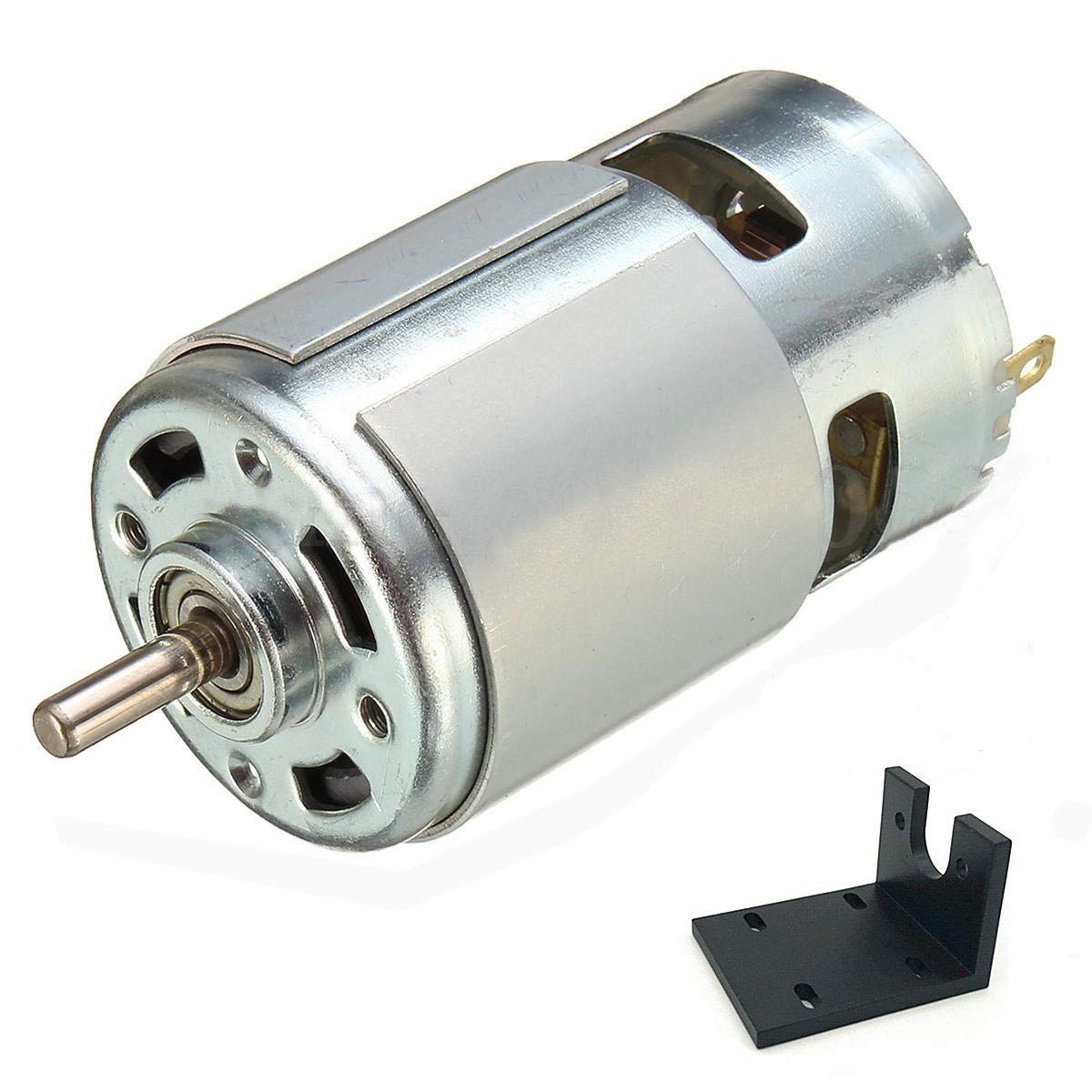
Can DC motors be used in robotics, and if so, what are some notable applications?
Yes, DC (Direct Current) motors can be used in robotics, and they are widely employed in various robotic applications. DC motors offer several advantages that make them suitable for robotic systems, including their controllability, compact size, and versatility. Here’s a detailed explanation of how DC motors are used in robotics and some notable applications:
DC Motors in Robotics:
DC motors are commonly used in robotics due to their ability to provide precise speed control and torque output. They can be easily controlled by adjusting the voltage applied to the motor, allowing for accurate and responsive motion control in robotic systems. Additionally, DC motors can be designed in compact sizes, making them suitable for applications with limited space and weight constraints.
There are two main types of DC motors used in robotics:
- DC Brushed Motors: These motors have a commutator and carbon brushes that provide the electrical connection to the rotating armature. They are relatively simple in design and cost-effective. However, they may require maintenance due to brush wear.
- DC Brushless Motors: These motors use electronic commutation instead of brushes, resulting in improved reliability and reduced maintenance requirements. They are often more efficient and offer higher power density compared to brushed motors.
Notable Applications of DC Motors in Robotics:
DC motors find applications in various robotic systems across different industries. Here are some notable examples:
1. Robotic Manipulators: DC motors are commonly used in robotic arms and manipulators to control the movement of joints and end-effectors. They provide precise control over position, speed, and torque, allowing robots to perform tasks such as pick-and-place operations, assembly, and material handling in industrial automation, manufacturing, and logistics.
2. Mobile Robots: DC motors are extensively utilized in mobile robots, including autonomous vehicles, drones, and rovers. They power the wheels or propellers, enabling the robot to navigate and move in different environments. DC motors with high torque output are particularly useful for off-road or rugged terrain applications.
3. Humanoid Robots: DC motors play a critical role in humanoid robots, which aim to replicate human-like movements and capabilities. They are employed in various joints, including those of the head, arms, legs, and hands, allowing humanoid robots to perform complex movements and tasks such as walking, grasping objects, and facial expressions.
4. Robotic Exoskeletons: DC motors are used in robotic exoskeletons, which are wearable devices designed to enhance human strength and mobility. They provide the necessary actuation and power for assisting or augmenting human movements, such as walking, lifting heavy objects, and rehabilitation purposes.
5. Educational Robotics: DC motors are popular in educational robotics platforms and kits, including those used in schools, universities, and hobbyist projects. They provide a cost-effective and accessible way for students and enthusiasts to learn about robotics, programming, and control systems.
6. Precision Robotics: DC motors with high-precision control are employed in applications that require precise positioning and motion control, such as robotic surgery systems, laboratory automation, and 3D printing. The ability of DC motors to achieve accurate and repeatable movements makes them suitable for tasks that demand high levels of precision.
These are just a few examples of how DC motors are used in robotics. The flexibility, controllability, and compactness of DC motors make them a popular choice in a wide range of robotic applications, contributing to the advancement of automation, exploration, healthcare, and other industries.


editor by CX 2024-04-22