
Product Description
Product Description
YEJ2 series electromatic-brake motors are improved products on the base of YEJ series. The technical properties of its motor conform to htere quirements of Y2 series. The performance of the brake assembly are improved. YEJ2 can make action proptly when the power of electric motor is off.
Motors of this series can continuously run at the rated power under the following conditions:
1. Altitude: Above sea level, not exceeding 1000m.
2. Ambient temperature: It varies with seasons but not exceeding +40° C
3. Voltage: 220/380V, 380/660V
4. Frequency: 50Hz, 60Hz.
5. Connection: Y-Connection for 3kw and below whereas; Delta-connection for 4 kw and above.
6. Duty: Continuous(S1)
7. Insulation Class: B, F
8. Protection: IP44, IP55 or IP54
| Technical data-YEJ series motor-2 poles -380v/50HZ | |||||||||
| type | Rated output | Full Load | Static braking torque | Max.braking time at No-load | Brake power | ||||
| Speed | Input Current | Efficiency | PowTypeer factor | ||||||
| KW | HP | RPM | Amp | Eff.% | P.F | N.m | S | W | |
| YEJ80M1-2 | 0.75 | 1.0 | 2825 | 1.81 | 75 | 0.84 | 7.5 | 0.20 | 50 |
| YEJ80M2-2 | 1.1 | 1.5 | 2825 | 2.52 | 77 | 0.86 | 7.5 | 0.20 | 50 |
| YEJ90S-2 | 1.5 | 2.0 | 2840 | 3.44 | 78 | 0.85 | 15 | 0.20 | 60 |
| YEJ90L-2 | 2.2 | 3.0 | 2840 | 4.83 | 80.5 | 0.86 | 15 | 0.20 | 60 |
| YEJ100L-2 | 3 | 4.0 | 2870 | 6.39 | 82 | 0.87 | 30 | 0.20 | 80 |
| YEJ112M-2 | 4 | 5.5 | 2880 | 8.17 | 85.5 | 0.87 | 40 | 0.25 | 110 |
| YEJ132S1-2 | 5.5 | 7.5 | 2900 | 11.10 | 85.5 | 0.88 | 75 | 0.25 | 130 |
| YEJ132S2-2 | 7.5 | 10.0 | 2900 | 15.00 | 86.2 | 0.88 | 75 | 0.25 | 130 |
| YEJ160M1-2 | 11 | 15 | 2930 | 21.80 | 87.2 | 0.88 | 150 | 0.35 | 150 |
| YEJ160M2-2 | 15 | 20 | 2930 | 29.40 | 88.2 | 0.88 | 150 | 0.35 | 150 |
| YEJ160L-2 | 18.5 | 25 | 2930 | 35.50 | 89.0 | 0.89 | 150 | 0.35 | 150 |
| YEJ180M-2 | 22 | 30 | 2940 | 42.20 | 89.0 | 0.89 | 200 | 0.35 | 150 |
| YEJ200L1-2 | 30 | 40 | 2950 | 56.90 | 90.0 | 0.89 | 300 | 0.45 | 200 |
| YEJ200L2-2 | 37 | 50 | 2950 | 69.80 | 90.5 | 0.89 | 300 | 0.45 | 200 |
| YEJ225M-2 | 45 | 60 | 2960 | 83.90 | 91.5 | 0.89 | 450 | 0.45 | 200 |
| Technical data-YEJ series motor-4 poles -380v/50HZ | |||||||||
| Type | Rated output | Full Load | Static braking torque | Max.braking time at No-load | Brake power | ||||
| Speed | Input Current | Efficiency | Power factor | ||||||
| KW | HP | RPM | Amp | Eff.% | P.F | N.m | S | W | |
| YEJ80M1-4 | 0.55 | 0.75 | 1390 | 1.51 | 73.0 | 0.76 | 7.5 | 0.20 | 50 |
| YEJ80M2-4 | 0.75 | 1.0 | 1390 | 2.01 | 74.5 | 0.76 | 7.5 | 0.20 | 50 |
| YEJ90S-4 | 1.1 | 1.5 | 1400 | 2.75 | 78.0 | 0.78 | 15 | 0.20 | 60 |
| YEJ90L-4 | 1.5 | 2.0 | 1400 | 3.65 | 79.0 | 0.79 | 15 | 0.20 | 60 |
| YEJ100L1-4 | 2.2 | 3.0 | 1420 | 5.03 | 81.0 | 0.82 | 30 | 0.20 | 80 |
| JET100L2-4 | 3.0 | 4.0 | 1420 | 6.82 | 82.5 | 0.81 | 30 | 0.20 | 80 |
| YEJ112M-4 | 4.0 | 5.5 | 1440 | 8.77 | 84.5 | 0.82 | 40 | 0.25 | 110 |
| YEJ132S-4 | 5.5 | 7.5 | 1440 | 11.60 | 85.5 | 0.84 | 75 | 0.25 | 130 |
| YEJ132M-4 | 7.5 | 10.0 | 1440 | 15.40 | 87.0 | 0.85 | 75 | 0.25 | 130 |
| YEJ160M-4 | 11 | 15 | 1460 | 22.60 | 88.0 | 0.84 | 150 | 0.35 | 150 |
| YEJ160L-4 | 15 | 20 | 1460 | 30.30 | 88.5 | 0.85 | 150 | 0.35 | 150 |
| YEJ180M-4 | 18.5 | 25 | 1465 | 35.90 | 91.0 | 0.86 | 200 | 0.35 | 150 |
| YEJ180L-4 | 22 | 30 | 1465 | 42.50 | 91.5 | 0.86 | 200 | 0.35 | 150 |
| YEJ200L-4 | 30 | 40 | 1470 | 56.80 | 92.2 | 0.87 | 300 | 0.45 | 200 |
| YEJ225S-4 | 37 | 50 | 1475 | 70.40 | 91.8 | 0.87 | 450 | 0.45 | 200 |
| YEJ225M-4 | 45 | 60 | 1475 | 84.20 | 92.3 | 0.88 | 450 | 0.45 | 200 |
| Technical data-YEJ series motor-6 poles -380v/50HZ | |||||||||
| Type | Rated output | Full Load | Static braking torque | Max.braking time at No-load | Brake power | ||||
| Speed | Input Current | Efficiency | Power factor | ||||||
| KW | HP | RPM | Amp | Eff.% | P.F | N.m | S | W | |
| YEJ90S-6 | 0.75 | 1.0 | 910 | 2.25 | 72.5 | 0.7 | 15 | 0.2 | 60 |
| YEJ90L-6 | 1.1 | 1.5 | 910 | 3.16 | 73.5 | 0.72 | 15 | 0.2 | 60 |
| YEJ100L-6 | 1.5 | 2.0 | 930 | 3.97 | 77.5 | 0.74 | 30 | 0.2 | 80 |
| YEJ112M-6 | 2.2 | 3.0 | 940 | 5.61 | 80.5 | 0.74 | 40 | 0.25 | 110 |
| YEJ132S-6 | 3.0 | 4.0 | 960 | 7.23 | 83.0 | 0.76 | 75 | 0.25 | 130 |
| YEJ132M1-6 | 4.0 | 5.5 | 960 | 9.40 | 84.0 | 0.77 | 75 | 0.25 | 130 |
| YEJ132M2-6 | 5.5 | 7.5 | 960 | 12.60 | 85.3 | 0.78 | 75 | 0.25 | 130 |
| YEJ160M-6 | 7.5 | 10.0 | 970 | 17.00 | 86.0 | 0.78 | 150 | 0.35 | 150 |
| YEJ160L-6 | 11 | 15 | 970 | 24.60 | 87.0 | 0.78 | 150 | 0.35 | 150 |
| YEJ180L-6 | 15 | 20 | 970 | 31.40 | 89.5 | 0.81 | 200 | 0.35 | 150 |
| YEJ200L1-6 | 18.5 | 25 | 975 | 37.70 | 89.8 | 0.83 | 300 | 0.45 | 200 |
| YEJ200L2-6 | 22 | 30 | 975 | 44.60 | 90.2 | 0.83 | 300 | 0.45 | 200 |
| YEJ225M-6 | 30 | 40 | 980 | 59.50 | 92.2 | 0.85 | 450 | 0.45 | 200 |
Detailed Photos
Our Advantages
We have more than 30years on all kinds of ac motors and gearmotor ,worm reducers producing ,nice price
What we do:
1.Stamping of lamination
2.Rotor die-casting
3.Winding and inserting – both manual and semi-automatically
4.Vacuum varnishing
5.Machining shaft, housing, end shields, etc…
6.Rotor balancing
7.Painting – both wet paint and powder coating
8.assembly
9.Packing
10.Inspecting spare parts every processing
11.100% test after each process and final test before packing.,
FAQ
Q: Do you offer OEM service?
A: Yes
Q: What is your payment term?
A: 30% T/T in advance, 70% balance when receiving B/L copy. Or irrevocable L/C.
Q: What is your lead time?
A: About 30 days after receiving deposit or original L/C.
Q: What certifiicates do you have?
A: We have CE, ISO. And we can apply for specific certificate for different country such as SONCAP for Nigeria, COI for Iran, SASO for Saudi Arabia, etc.
/* January 22, 2571 19:08:37 */!function(){function s(e,r){var a,o={};try{e&&e.split(“,”).forEach(function(e,t){e&&(a=e.match(/(.*?):(.*)$/))&&1
| Application: | Industrial ,Universal ,etc |
|---|---|
| Speed: | Constant Speed |
| Number of Stator: | Three-Phase |
| Function: | Control |
| Casing Protection: | Protection Type |
| Number of Poles: | 2.4.6.8p |
| Samples: |
US$ 829/Piece
1 Piece(Min.Order) | |
|---|
| Customization: |
Available
|
|
|---|
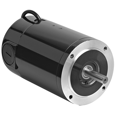
How does the speed control of a DC motor work, and what methods are commonly employed?
The speed control of a DC (Direct Current) motor is essential for achieving precise control over its rotational speed. Various methods can be employed to regulate the speed of a DC motor, depending on the specific application requirements. Here’s a detailed explanation of how speed control of a DC motor works and the commonly employed methods:
1. Voltage Control:
One of the simplest methods to control the speed of a DC motor is by varying the applied voltage. By adjusting the voltage supplied to the motor, the electromotive force (EMF) induced in the armature windings can be controlled. According to the principle of electromagnetic induction, the speed of the motor is inversely proportional to the applied voltage. Therefore, reducing the voltage decreases the speed, while increasing the voltage increases the speed. This method is commonly used in applications where a simple and inexpensive speed control mechanism is required.
2. Armature Resistance Control:
Another method to control the speed of a DC motor is by varying the armature resistance. By inserting an external resistance in series with the armature windings, the total resistance in the circuit increases. This increase in resistance reduces the armature current, thereby reducing the motor’s speed. Conversely, reducing the resistance increases the armature current and the motor’s speed. However, this method results in significant power loss and reduced motor efficiency due to the dissipation of excess energy as heat in the external resistance.
3. Field Flux Control:
Speed control can also be achieved by controlling the magnetic field strength of the motor’s stator. By altering the field flux, the interaction between the armature current and the magnetic field changes, affecting the motor’s speed. This method can be accomplished by adjusting the field current through the field windings using a field rheostat or by employing a separate power supply for the field windings. By increasing or decreasing the field flux, the speed of the motor can be adjusted accordingly. This method offers good speed regulation and efficiency but requires additional control circuitry.
4. Pulse Width Modulation (PWM):
Pulse Width Modulation is a widely used technique for speed control in DC motors. It involves rapidly switching the applied voltage on and off at a high frequency. The duty cycle, which represents the percentage of time the voltage is on, is varied to control the effective voltage applied to the motor. By adjusting the duty cycle, the average voltage across the motor is modified, thereby controlling its speed. PWM provides precise speed control, high efficiency, and low power dissipation. It is commonly employed in applications such as robotics, industrial automation, and electric vehicles.
5. Closed-Loop Control:
In closed-loop control systems, feedback from the motor’s speed or other relevant parameters is used to regulate the speed. Sensors such as encoders or tachometers measure the motor’s actual speed, which is compared to the desired speed. The difference, known as the error signal, is fed into a control algorithm that adjusts the motor’s input voltage or other control parameters to minimize the error and maintain the desired speed. Closed-loop control provides excellent speed regulation and accuracy, making it suitable for applications that require precise speed control, such as robotics and CNC machines.
These methods of speed control provide flexibility and adaptability to various applications, allowing DC motors to be effectively utilized in a wide range of industries and systems.
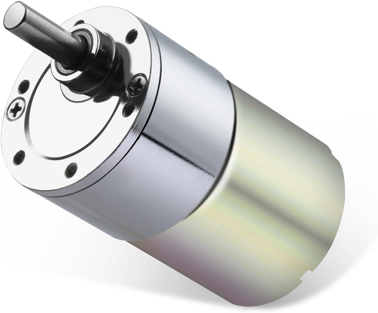
What role does commutation play in the operation of a DC motor?
In the operation of a DC (Direct Current) motor, commutation plays a crucial role in ensuring the continuous rotation of the motor and the conversion of electrical energy into mechanical motion. It is the process by which the direction of the current in the armature winding is periodically reversed to maintain a constant torque and facilitate the rotation of the motor. Here’s a detailed explanation of the role of commutation in the operation of a DC motor:
Commutation is necessary in a DC motor because the magnetic field generated by the armature winding needs to be constantly aligned with the stator’s magnetic field for efficient torque production. The stator of a DC motor typically consists of permanent magnets or electromagnets that create a fixed magnetic field. The armature winding, located on the rotor, produces a magnetic field that interacts with the stator’s field to generate torque.
The commutation process is achieved through the use of a commutator and brushes. The commutator is a cylindrical ring with multiple segments, while the brushes are conductive contacts that make physical contact with the commutator segments. The armature winding is connected to the commutator, and as the rotor spins, the brushes maintain contact with different segments.
As the rotor rotates, the commutator and brushes ensure that the direction of the current in the armature winding is reversed at specific intervals. This reversal of current flow is necessary to maintain a consistent torque in the same rotational direction. Without commutation, the torque generated by the motor would fluctuate in both magnitude and direction, leading to instability and erratic motor behavior.
The commutation process involves two stages: mechanical commutation and electrical commutation.
1. Mechanical Commutation: As the rotor rotates, the brushes make contact with different segments of the commutator. The segments are insulated from each other to prevent short circuits. When the brushes move from one segment to another, the current flowing through the armature winding is switched to a different coil or set of coils. This mechanical switching ensures that the magnetic fields produced by the winding are properly aligned with the stator’s field, resulting in continuous torque production.
2. Electrical Commutation: The reversal of current in the armature winding is achieved through electrical commutation. When the brushes make contact with a new commutator segment, the current flow in the winding is redirected to maintain the desired torque direction. The timing and sequence of the current reversal are critical to ensure smooth and efficient motor operation.
The commutation process in a DC motor is a dynamic and continuous operation. It allows for the conversion of electrical energy into mechanical motion by providing a consistent torque output. The efficiency and performance of the motor are greatly influenced by the quality and effectiveness of the commutation process.
In summary, commutation plays a vital role in the operation of a DC motor by ensuring the continuous rotation of the motor and the production of consistent torque. It involves the mechanical and electrical switching of the current direction in the armature winding, facilitated by the commutator and brushes.
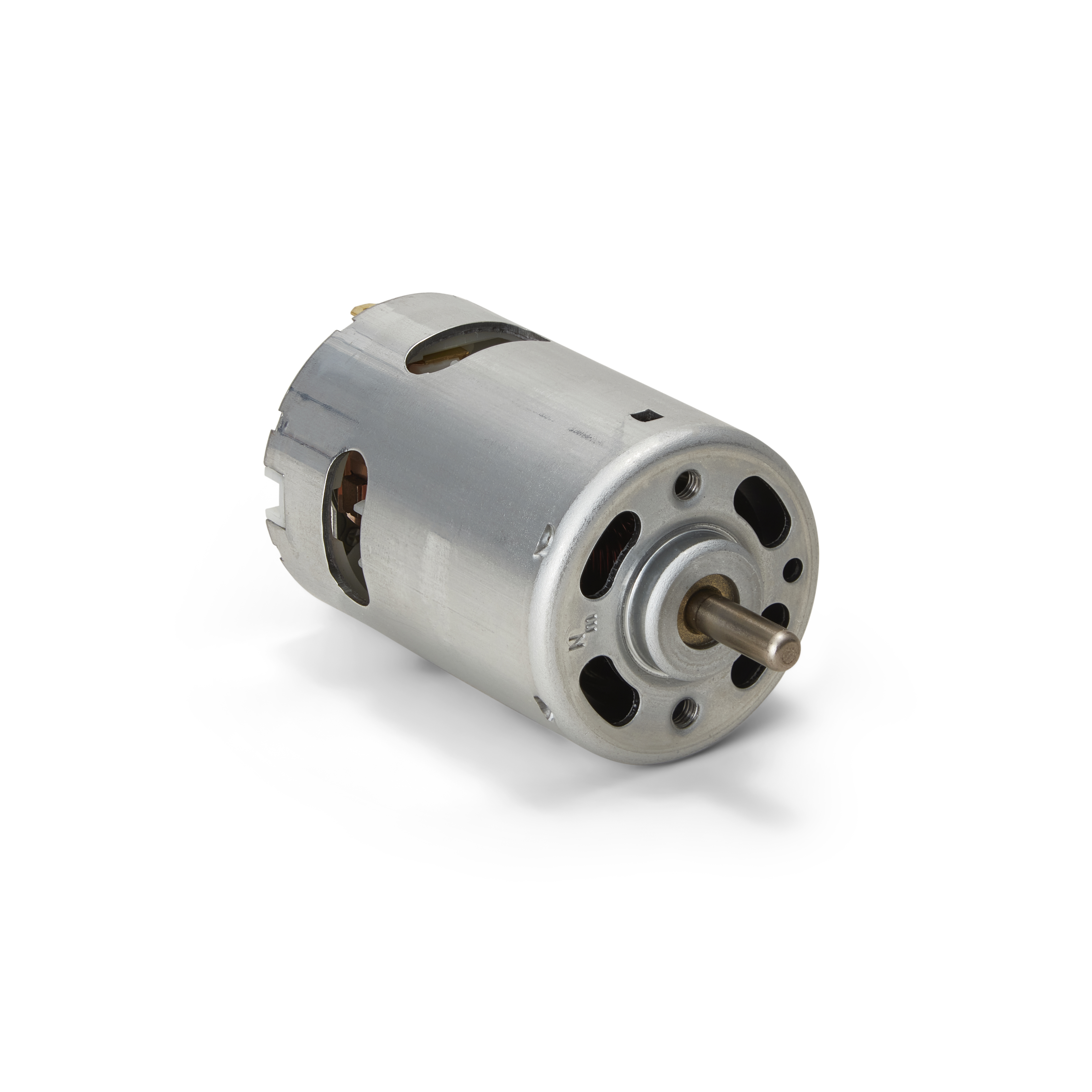
What are the advantages and disadvantages of using DC motors in automotive applications?
DC (Direct Current) motors have been used in automotive applications for many years, although they have been largely replaced by other motor types such as AC (Alternating Current) motors and brushless DC motors in modern vehicles. However, there are still some advantages and disadvantages associated with using DC motors in automotive applications. Here’s a detailed explanation of the advantages and disadvantages:
Advantages of Using DC Motors in Automotive Applications:
1. Cost: DC motors tend to be less expensive compared to other motor types, such as AC motors or brushless DC motors. This cost advantage can make them an attractive option for certain automotive applications, especially in budget-conscious scenarios.
2. Simple Control: DC motors have a relatively simple control system. By adjusting the voltage applied to the motor, the speed and torque can be easily controlled. This simplicity of control can be advantageous in automotive applications where basic speed control is sufficient.
3. High Torque at Low Speeds: DC motors can provide high torque even at low speeds, making them suitable for applications that require high starting torque or precise low-speed control. This characteristic can be beneficial for automotive applications such as power windows, windshield wipers, or seat adjustments.
4. Compact Size: DC motors can be designed in compact sizes, making them suitable for automotive applications where space is limited. Their small form factor allows for easier integration into tight spaces within the vehicle.
Disadvantages of Using DC Motors in Automotive Applications:
1. Limited Efficiency: DC motors are typically less efficient compared to other motor types, such as AC motors or brushless DC motors. They can experience energy losses due to brush friction and electrical resistance, resulting in lower overall efficiency. Lower efficiency can lead to increased power consumption and reduced fuel economy in automotive applications.
2. Maintenance Requirements: DC motors that utilize brushes for commutation require regular maintenance. The brushes can wear out over time and may need to be replaced periodically, adding to the maintenance and operating costs. In contrast, brushless DC motors or AC motors do not have this maintenance requirement.
3. Limited Speed Range: DC motors have a limited speed range compared to other motor types. They may not be suitable for applications that require high-speed operation or a broad range of speed control. In automotive applications where high-speed performance is crucial, other motor types may be preferred.
4. Electromagnetic Interference (EMI): DC motors can generate electromagnetic interference, which can interfere with the operation of other electronic components in the vehicle. This interference may require additional measures, such as shielding or filtering, to mitigate its effects and ensure proper functioning of other vehicle systems.
5. Brush Wear and Noise: DC motors that use brushes can produce noise during operation, and the brushes themselves can wear out over time. This brush wear can result in increased noise levels and potentially impact the overall lifespan and performance of the motor.
While DC motors offer certain advantages in terms of cost, simplicity of control, and high torque at low speeds, they also come with disadvantages such as limited efficiency, maintenance requirements, and electromagnetic interference. These factors have led to the adoption of other motor types, such as brushless DC motors and AC motors, in many modern automotive applications. However, DC motors may still find use in specific automotive systems where their characteristics align with the requirements of the application.


editor by CX 2024-05-03