
Product Description
High-speed doors servo control system
DC High Speed Curtain Roller Shutter Tubular Central Motor
Features
- Intelligent human-computer interaction interface, LCD display, built-in Chinese and English
- Convenient wiring and simple operation
- Built-in brake released battery,the brake can be quickly released with 1 button when power off
- Low noise, stable operation and high efficiency
- High-quality IPM intelligent module, with strong performance and full protection function
- Record running time and number of times, lock and maintenance time can be set
- Real-time monitor external signals and system alarm functions
- Input and output ports can be edited to set multiple functions
- The product is suitable for all kinds of PVC high-speed doors,PVC high-speed Fold-up doors and spiral doors.
Technical Parameter
| Model | FD300 | ||
| Rated Power | 0.75kw | 1.5kw | 2.5kw |
| Brake Release Battery | None | Built-in | |
| Input Voltage | 1P,AC220V±15%/50~60Hz | ||
| Limit Control | Ab olute Encoder,Mechanical Limit | ||
| Overload Capacity | 300% Rated 10s,150% Rated 60s | ||
| Output Power | DC24V/1A | ||
| Temperature | -20ºC ~ 50ºC | ||
| Dimension | 360×23 ×100mm | ||
| Weight | 5.2kg | ||
Brief description of common parameters
Low power silent high-speed servo motor
Features
- High speed, rated speed 3000 rpm, maximum 5000 rpm
- Aviation aluminum shell, exquisite appearance and good heat dissipati n
- Built-in absolute encoder, easy to install
- Constant high torque output, up to 300 overload capacity
- Applicable to a wide range of environments, -40ºC~70ºC
- No mechanical brake, quiet and stable
- Advanced short-circuit electromagnetic brake, self-locking after power off
| Size Type |
A | B | C | D | E | F | Weight (kg) | |
| 0.75kw | RV050 | 120 | 145 | 90 | 300 | 150 | 30 | 7.7 |
| 0.75kw | RV063 | 145 | 175 | 110 | 325 | 150 | 30 | 9.9 |
| 1.1kw | RV050 | 120 | 145 | 90 | 330 | 180 | 30 | 8.6 |
| 1.1kw | RV063 | 145 | 175 | 110 | 355 | 180 | 30 | 10.8 |
| Model | FDHDM22150 | |
| Rated Power | 0.75kw | 1.1kw |
| Insulation Gr de | F | |
| IP | IP65 | |
| Encoder | bsolute Encoder Built-in | |
| Brake | none mechanical brake | |
| Output Rotating Speed | 3000RPM | |
| Output Torque | 2.39N.m | 3.5N.m |
| Reduction Gear | 050(063 Optional)Standard 1:30 | |
High-power high-speed servo motor
Features
- High speed, rated speed 2500 rpm, maximum 4000 rpm
- Aviation aluminum shell, exquisite appearance and good heat dissipation
- Built-in absolute encoder, easy to install
- Constant high torque output, up to 300 overload capacity
- Applicable to a wide range of environments, -40ºC~70ºC
- DC 24V mechanical brake, easily released by 1 key of the controller when power off
| Size Type | A | B | C | D | E | F | Weight (kg) | |
| 1.5kw | RV063 | 144 | 200 | 103 | 403 | 236 | 30 | 16.2 |
| 2.0kw | RV063 | 144 | 200 | 103 | 410 | 249 | 30 | 17.5 |
| 2.5kw | RV063 | 144 | 200 | 103 | 452 | 252 | 30 | 18.5 |
| Model | FDHDM22220 | ||
| Rated Power | 1.5kw | 2kw | 2.5kw |
| Insulation Gr de | F | ||
| IP | IP65 | ||
| Encoder | Absolute Encoder B ilt-in | ||
| Brake | DC24 Brake | ||
| Output Rotating Speed | 2500RPM | ||
| Output Torque | 6N.m | 8N.m | 10N.m |
| Reduction Gear | 063(075 Optional)Standard 1:25 | ||
| Reduction Gear | D | b | M | N | KE | C | E | L |
| RV50 | 25 | 8 | 85 | 70 | M8×10 | 120 | 144 | 85 |
| RV63 | 25 | 8 | 95 | 80 | M8×14 | 144 | 174 | 103 |
| RV75 | 28 | 8 | 115 | 95 | M8×14 | 174 | 205 | 113 |
| RV90 | 28 | 10 | 130 | 110 | M10×10 | 208 | 238 | 130 |
High-speed tubular servo motor
90/130 Planetary gear servo motor
/* January 22, 2571 19:08:37 */!function(){function s(e,r){var a,o={};try{e&&e.split(“,”).forEach(function(e,t){e&&(a=e.match(/(.*?):(.*)$/))&&1
| Structure: | Straight Arm |
|---|---|
| Driving Type: | Electromechanical |
| Electric Current Type: | AC |
| Brand: | Everbright |
| Output Power: | DC24V / 1A |
| Input Voltage: | 1p,AC220V±15%/50~60Hz |
| Samples: |
US$ 300/Piece
1 Piece(Min.Order) | |
|---|
| Customization: |
Available
|
|
|---|
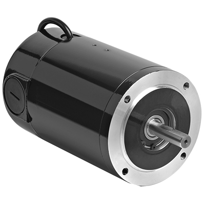
How does the speed control of a DC motor work, and what methods are commonly employed?
The speed control of a DC (Direct Current) motor is essential for achieving precise control over its rotational speed. Various methods can be employed to regulate the speed of a DC motor, depending on the specific application requirements. Here’s a detailed explanation of how speed control of a DC motor works and the commonly employed methods:
1. Voltage Control:
One of the simplest methods to control the speed of a DC motor is by varying the applied voltage. By adjusting the voltage supplied to the motor, the electromotive force (EMF) induced in the armature windings can be controlled. According to the principle of electromagnetic induction, the speed of the motor is inversely proportional to the applied voltage. Therefore, reducing the voltage decreases the speed, while increasing the voltage increases the speed. This method is commonly used in applications where a simple and inexpensive speed control mechanism is required.
2. Armature Resistance Control:
Another method to control the speed of a DC motor is by varying the armature resistance. By inserting an external resistance in series with the armature windings, the total resistance in the circuit increases. This increase in resistance reduces the armature current, thereby reducing the motor’s speed. Conversely, reducing the resistance increases the armature current and the motor’s speed. However, this method results in significant power loss and reduced motor efficiency due to the dissipation of excess energy as heat in the external resistance.
3. Field Flux Control:
Speed control can also be achieved by controlling the magnetic field strength of the motor’s stator. By altering the field flux, the interaction between the armature current and the magnetic field changes, affecting the motor’s speed. This method can be accomplished by adjusting the field current through the field windings using a field rheostat or by employing a separate power supply for the field windings. By increasing or decreasing the field flux, the speed of the motor can be adjusted accordingly. This method offers good speed regulation and efficiency but requires additional control circuitry.
4. Pulse Width Modulation (PWM):
Pulse Width Modulation is a widely used technique for speed control in DC motors. It involves rapidly switching the applied voltage on and off at a high frequency. The duty cycle, which represents the percentage of time the voltage is on, is varied to control the effective voltage applied to the motor. By adjusting the duty cycle, the average voltage across the motor is modified, thereby controlling its speed. PWM provides precise speed control, high efficiency, and low power dissipation. It is commonly employed in applications such as robotics, industrial automation, and electric vehicles.
5. Closed-Loop Control:
In closed-loop control systems, feedback from the motor’s speed or other relevant parameters is used to regulate the speed. Sensors such as encoders or tachometers measure the motor’s actual speed, which is compared to the desired speed. The difference, known as the error signal, is fed into a control algorithm that adjusts the motor’s input voltage or other control parameters to minimize the error and maintain the desired speed. Closed-loop control provides excellent speed regulation and accuracy, making it suitable for applications that require precise speed control, such as robotics and CNC machines.
These methods of speed control provide flexibility and adaptability to various applications, allowing DC motors to be effectively utilized in a wide range of industries and systems.
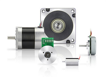
What is the significance of back EMF (electromotive force) in DC motor performance?
The significance of back EMF (electromotive force) in DC motor performance is crucial to understanding the behavior and operation of DC motors. Back EMF is an inherent characteristic of DC motors and plays a pivotal role in their efficiency, speed regulation, and overall performance. Here’s a detailed explanation of the significance of back EMF in DC motor performance:
When a DC motor operates, it generates a voltage known as back EMF or counter electromotive force. This voltage opposes the applied voltage and is caused by the rotation of the motor’s armature within the magnetic field. The back EMF is directly proportional to the rotational speed of the motor.
The significance of back EMF can be understood through the following aspects:
1. Speed Regulation:
Back EMF is crucial for regulating the speed of a DC motor. As the motor rotates faster, the back EMF increases, which reduces the effective voltage across the motor’s armature. Consequently, the armature current decreases, limiting the motor’s speed. This self-regulating characteristic helps maintain a relatively constant speed under varying load conditions. It allows the motor to deliver the required torque while preventing excessive speed that can potentially damage the motor or the driven equipment.
2. Efficiency:
Back EMF plays a significant role in the efficiency of a DC motor. When the motor is loaded and drawing current, the power supplied to the motor is the product of the armature current and the applied voltage. However, the electrical power converted into mechanical power is reduced by the power consumed by the back EMF. The back EMF represents the energy returned to the power supply as the motor generates its own voltage. By reducing the effective voltage across the motor, it helps minimize power losses due to electrical resistance and improves the overall efficiency of the motor.
3. Motor Protection:
The presence of back EMF also provides a level of protection to the motor. When a DC motor is operating and the load on the motor suddenly decreases, such as when the driven equipment is disconnected, the motor’s speed can increase rapidly. This increase in speed leads to a higher back EMF, which reduces the armature current and prevents excessive current flow. By limiting the current, the back EMF helps protect the motor from overloading and potential damage.
4. Voltage Regulation:
Back EMF affects the voltage regulation in a DC motor. When the motor is operating, the back EMF opposes the applied voltage. As the motor load increases, the voltage drop across the armature resistance and other internal losses also increase. The back EMF helps compensate for these voltage drops, ensuring that the motor receives an adequate voltage to maintain its performance and torque output.
5. Control and Dynamic Response:
Back EMF provides valuable information for motor control and dynamic response. By measuring the back EMF voltage, the rotational speed of the motor can be estimated, allowing for precise speed control and feedback. This information is crucial for applications that require accurate speed regulation, such as robotics or industrial automation.
In summary, the significance of back EMF in DC motor performance cannot be overstated. It influences speed regulation, efficiency, motor protection, voltage regulation, and control capabilities. By understanding and utilizing the inherent characteristics of back EMF, engineers can design and optimize DC motor systems for various applications, ensuring reliable and efficient operation.
Are there innovations or emerging technologies in the field of DC motor design?
Yes, there have been several innovations and emerging technologies in the field of DC (Direct Current) motor design. These advancements aim to improve the performance, efficiency, reliability, and overall capabilities of DC motors. Here’s a detailed explanation of some notable innovations and emerging technologies in DC motor design:
1. Brushless DC Motors:
One significant advancement in DC motor design is the development and widespread adoption of brushless DC motors (BLDC motors). Unlike traditional DC motors that use brushes for commutation, BLDC motors employ electronic commutation through the use of permanent magnets and motor controller circuits. This eliminates the need for brushes, reducing maintenance requirements and improving overall motor efficiency and lifespan. BLDC motors offer higher torque density, smoother operation, better speed control, and improved energy efficiency compared to conventional brushed DC motors.
2. High-Efficiency Materials:
The use of high-efficiency materials in DC motor design has been an area of focus for improving motor performance. Advanced magnetic materials, such as neodymium magnets, have allowed for stronger and more compact motor designs. These materials increase the motor’s power density, enabling higher torque output and improved efficiency. Additionally, advancements in materials used for motor windings and core laminations have reduced electrical losses and improved overall motor efficiency.
3. Power Electronics and Motor Controllers:
Advancements in power electronics and motor control technologies have greatly influenced DC motor design. The development of sophisticated motor controllers and efficient power electronic devices enables precise control of motor speed, torque, and direction. These technologies have resulted in more efficient and reliable motor operation, reduced energy consumption, and enhanced motor performance in various applications.
4. Integrated Motor Systems:
Integrated motor systems combine the motor, motor controller, and associated electronics into a single unit. These integrated systems offer compact designs, simplified installation, and improved overall performance. By integrating the motor and controller, issues related to compatibility and communication between separate components are minimized. Integrated motor systems are commonly used in applications such as robotics, electric vehicles, and industrial automation.
5. IoT and Connectivity:
The integration of DC motors with Internet of Things (IoT) technologies and connectivity has opened up new possibilities for monitoring, control, and optimization of motor performance. By incorporating sensors, actuators, and connectivity features, DC motors can be remotely monitored, diagnosed, and controlled. This enables predictive maintenance, energy optimization, and real-time performance adjustments, leading to improved efficiency and reliability in various applications.
6. Advanced Motor Control Algorithms:
Advanced motor control algorithms, such as sensorless control and field-oriented control (FOC), have contributed to improved performance and efficiency of DC motors. Sensorless control techniques eliminate the need for additional sensors by leveraging motor current and voltage measurements to estimate rotor position. FOC algorithms optimize motor control by aligning the magnetic field with the rotor position, resulting in improved torque and efficiency, especially at low speeds.
These innovations and emerging technologies in DC motor design have revolutionized the capabilities and performance of DC motors. Brushless DC motors, high-efficiency materials, advanced motor control techniques, integrated motor systems, IoT connectivity, and advanced control algorithms have collectively contributed to more efficient, reliable, and versatile DC motor solutions across various industries and applications.


editor by CX 2024-05-03