
Product Description
Product Description
Good price 5.5KW Flange mounting new style Hypoid Gear Motors for sale
1.KM series Helical-hypoid Gearbox’s Characteristics
KM series helical-hypoid gearbox is a new-generation of product developed by Aokman. With a compromise of advanced technology both at home and abroad, its main features are as follows:
(1) Driven by hypoid gears, which has big ratios.
(2) Large output torque, high efficiency, energy saving and environmental protection.
(3) High-quality aluminum alloy housing, and light in weight and non-rusting.
(4) Smooth in running and low in noise, and can work long time in dreadful conditions.
(5) Good-looking in appearance, durable in service life and small in volume.
(6) Suitable for all round installation, wide application and easy use.
(7) The mounting dimension of KM series helical-hypoid gearbox are compatible with RV series worm gearbox.
(8) Modular and multi-structure can meet the demands of various conditions.
Detailed Photos
2. KM series Helical-hypoid Gearbox’s Main Materials
(1) Housing: die-cast aluminum alloy (frame size 27 to 57)
(2) Gear wheel: 20CrMnTiH1 carbonizing & quenching heat treatment make the hardness of gears surface be up to 56-62 HRC, and be retained carburization layers thickness between 0.3 and 0.5mm after precise grinding.
3. KM series Helical-hypoid Gearbox’s Surface Painting
Aluminum alloy housing:
(1) Shot blasting and special antiseptic treatment on the aluminum alloy surface.
(2) After phosphating, spray the RAL9571 silver white paint.4.Gearbox Parameters
Product Parameters
| Models | Stage | Nominal Ratio | Output Speed (n2)* | Max. Torque | Input Shaft Dia. | Output Hole Dia. | Output Shaft Dia. |
| KM050 | 3 Stage | 50~300 | 4.8~27 | 130N.m | Φ11 | Φ20, Φ24 | Φ25 |
| 2 Stage | 7.5~60 | 24~181 | 130N.m | Φ11 | |||
| KM063 | 3 Stage | 50~300 | 4.6~27 | 200N.m | Φ11 | Φ25, Φ28 | Φ25 |
| 2 Stage | 7.5~60 | 23~184 | 200N.m | Φ14 | |||
| KM075 | 3 Stage | 50~300 | 4.7~28 | 350N.m | Φ14 | Φ28, Φ30, Φ35 | Φ28 |
| 2 Stage | 7.5~60 | 24~187 | 350N.m | Φ16 | |||
| KM090 | 3 Stage | 50~300 | 4.7~28 | 500N.m | Φ14 | Φ35, Φ38 | Φ35 |
| 2 Stage | 7.5~60 | 24~187 | 500N.m | Φ19 | |||
| KM110 | 3 Stage | 50~300 | 4.7~27 | 750N.m | Φ19 | Φ40, Φ42 | Φ42 |
| 2 Stage | 7.5~60 | 24~187 | 750N.m | Φ24 |
Packaging & Shipping
Company Profile
Our Advantages
After Sales Service
| Pre-sale services | 1. Select equipment model. |
| 2.Design and manufacture products according to clients’ special requirement. | |
| 3.Train technical personal for clients | |
| Services during selling | 1.Pre-check and accept products ahead of delivery. |
| 2. Help clients to draft solving plans. | |
| After-sale services | 1.Assist clients to prepare for the first construction scheme. |
| 2. Train the first-line operators. | |
| 3.Take initiative to eliminate the trouble rapidly. | |
| 4. Provide technical exchanging. |
FAQ
1.Q:What kinds of gearbox can you produce for us?
A:Main products of our company: UDL series speed variator,RV series worm gear reducer, ATA series shaft mounted gearbox, X,B series gear reducer,
P series planetary gearbox and R, S, K, and F series helical-tooth reducer, more
than 1 hundred models and thousands of specifications
2.Q:Can you make as per custom drawing?
A: Yes, we offer customized service for customers.
3.Q:What is your terms of payment ?
A: 30% Advance payment by T/T after signing the contract.70% before delivery
4.Q:What is your MOQ?
A: 1 Set
If you have any demand for our products please feel free to contact me. /* March 10, 2571 17:59:20 */!function(){function s(e,r){var a,o={};try{e&&e.split(“,”).forEach(function(e,t){e&&(a=e.match(/(.*?):(.*)$/))&&1
| Application: | Motor, Machinery |
|---|---|
| Function: | Speed Changing, Speed Reduction |
| Layout: | Orthogonal |
| Hardness: | Hardened Tooth Surface |
| Installation: | Industry |
| Step: | Double or Three-Step |
| Customization: |
Available
|
|
|---|
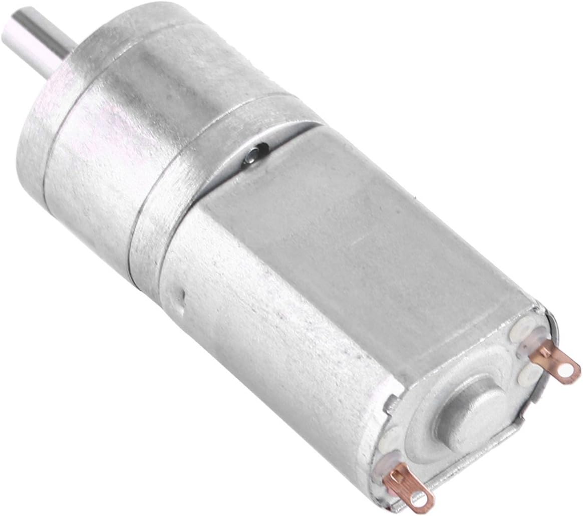
What types of feedback mechanisms are commonly integrated into gear motors for control?
Gear motors often incorporate feedback mechanisms to provide control and improve their performance. These feedback mechanisms enable the motor to monitor and adjust its operation based on various parameters. Here are some commonly integrated feedback mechanisms in gear motors:
1. Encoder Feedback:
An encoder is a device that provides position and speed feedback by converting the motor’s mechanical motion into electrical signals. Encoders commonly used in gear motors include:
- Incremental Encoders: These encoders provide information about the motor’s shaft position and speed relative to a reference point. They generate pulses as the motor rotates, allowing precise measurement of position and speed changes.
- Absolute Encoders: Absolute encoders provide the precise position of the motor’s shaft within a full revolution. They do not require a reference point and provide accurate feedback even after power loss or motor restart.
2. Hall Effect Sensors:
Hall effect sensors use the principle of the Hall effect to detect the presence and strength of a magnetic field. They are commonly used in gear motors for speed and position sensing. Hall effect sensors provide feedback by detecting changes in the motor’s magnetic field and converting them into electrical signals.
3. Current Sensors:
Current sensors monitor the electrical current flowing through the motor’s windings. By measuring the current, these sensors provide feedback regarding the motor’s torque, load conditions, and power consumption. Current sensors are essential for motor control strategies such as current limiting, overcurrent protection, and closed-loop control.
4. Temperature Sensors:
Temperature sensors are integrated into gear motors to monitor the motor’s temperature. They provide feedback on the motor’s thermal conditions, allowing the control system to adjust the motor’s operation to prevent overheating. Temperature sensors are crucial for ensuring the motor’s reliability and preventing damage due to excessive heat.
5. Hall Effect Limit Switches:
Hall effect limit switches are used to detect the presence or absence of a magnetic field within a specific range. They are commonly employed as end-of-travel or limit switches in gear motors. Hall effect limit switches provide feedback to the control system, indicating when the motor has reached a specific position or when it has moved beyond the allowed range.
6. Resolver Feedback:
A resolver is an electromagnetic device used to determine the position and speed of a rotating shaft. It provides feedback by generating sine and cosine signals that correspond to the shaft’s angular position. Resolver feedback is commonly used in high-performance gear motors requiring accurate position and speed control.
These feedback mechanisms, when integrated into gear motors, enable precise control, monitoring, and adjustment of various motor parameters. By utilizing feedback signals from encoders, Hall effect sensors, current sensors, temperature sensors, limit switches, or resolvers, the control system can optimize the motor’s performance, ensure accurate positioning, maintain speed control, and protect the motor from excessive loads or overheating.
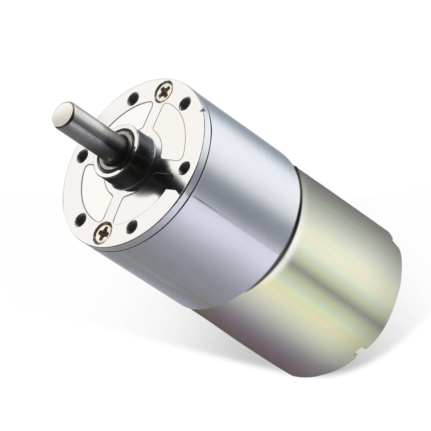
What are some common challenges or issues associated with gear motors, and how can they be addressed?
Gear motors, like any mechanical system, can face certain challenges or issues that may affect their performance, reliability, or longevity. However, many of these challenges can be addressed through proper design, maintenance, and operational practices. Here are some common challenges associated with gear motors and potential solutions:
1. Gear Wear and Failure:
Over time, gears in a gear motor can experience wear, resulting in decreased performance or even failure. The following measures can address this challenge:
- Proper Lubrication: Regular lubrication with the appropriate lubricant can minimize friction and wear between gear teeth. It is essential to follow manufacturer recommendations for lubrication intervals and use high-quality lubricants suitable for the specific gear motor.
- Maintenance and Inspection: Routine maintenance and periodic inspections can help identify early signs of gear wear or damage. Timely replacement of worn gears or components can prevent further damage and ensure the gear motor’s optimal performance.
- Material Selection: Choosing gears made from durable and wear-resistant materials, such as hardened steel or specialized alloys, can increase their lifespan and resistance to wear.
2. Backlash and Inaccuracy:
Backlash, as discussed earlier, can introduce inaccuracies in gear motor systems. The following approaches can help address this issue:
- Anti-Backlash Gears: Using anti-backlash gears, which are designed to minimize or eliminate backlash, can significantly reduce inaccuracies caused by gear play.
- Tight Manufacturing Tolerances: Ensuring precise manufacturing tolerances during gear production helps minimize backlash and improve overall accuracy.
- Backlash Compensation: Implementing control algorithms or mechanisms to compensate for backlash can help mitigate its effects and improve the accuracy of the gear motor.
3. Noise and Vibrations:
Gear motors can generate noise and vibrations during operation, which may be undesirable in certain applications. The following strategies can help mitigate this challenge:
- Noise Dampening: Incorporating noise-dampening features, such as vibration-absorbing materials or isolation mounts, can reduce noise and vibrations transmitted from the gear motor to the surrounding environment.
- Quality Gears and Bearings: Using high-quality gears and bearings can minimize vibrations and noise generation. Precision-machined gears and well-maintained bearings help ensure smooth operation and reduce unwanted noise.
- Proper Alignment: Ensuring accurate alignment of gears, shafts, and other components reduces the likelihood of noise and vibrations caused by misalignment. Regular inspections and adjustments can help maintain optimal alignment.
4. Overheating and Thermal Management:
Heat buildup can be a challenge in gear motors, especially during prolonged or heavy-duty operation. Effective thermal management techniques can address this issue:
- Adequate Ventilation: Providing proper ventilation and airflow around the gear motor helps dissipate heat. This can involve designing cooling fins, incorporating fans or blowers, or ensuring sufficient clearance for air circulation.
- Heat Dissipation Materials: Using heat-dissipating materials, such as aluminum or copper, in motor housings or heat sinks can improve heat dissipation and prevent overheating.
- Monitoring and Control: Implementing temperature sensors and thermal protection mechanisms allows for real-time monitoring of the gear motor’s temperature. If the temperature exceeds safe limits, the motor can be automatically shut down or adjusted to prevent damage.
5. Load Variations and Shock Loads:
Unexpected load variations or shock loads can impact the performance and durability of gear motors. The following measures can help address this challenge:
- Proper Sizing and Selection: Choosing gear motors with appropriate torque and load capacity ratings for the intended application helps ensure they can handle expected load variations and occasional shock loads without exceeding their limits.
- Shock Absorption: Incorporating shock-absorbing mechanisms, such as dampers or resilient couplings, can help mitigate the effects of sudden load changes or impacts on the gear motor.
- Load Monitoring: Implementing load monitoring systems or sensors allows for real-time monitoring of load variations. This information can be used to adjust operation or trigger protective measures when necessary.
By addressing these common challenges associated with gear motors through appropriate design considerations, regular maintenance, and operational practices, it is possible to enhance their performance, reliability, and longevity.
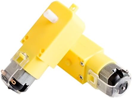
In which industries are gear motors commonly used, and what are their primary applications?
Gear motors find widespread use in various industries due to their versatility, reliability, and ability to provide controlled mechanical power. They are employed in a wide range of applications that require precise power transmission and speed control. Here’s a detailed explanation of the industries where gear motors are commonly used and their primary applications:
1. Robotics and Automation:
Gear motors play a crucial role in robotics and automation industries. They are used in robotic arms, conveyor systems, automated assembly lines, and other robotic applications. Gear motors provide the required torque, speed control, and directional control necessary for the precise movements and operations of robots. They enable accurate positioning, gripping, and manipulation tasks in industrial and commercial automation settings.
2. Automotive Industry:
The automotive industry extensively utilizes gear motors in various applications. They are used in power windows, windshield wipers, HVAC systems, seat adjustment mechanisms, and many other automotive components. Gear motors provide the necessary torque and speed control for these systems, enabling smooth and efficient operation. Additionally, gear motors are also utilized in electric and hybrid vehicles for powertrain applications.
3. Manufacturing and Machinery:
Gear motors find wide application in the manufacturing and machinery sector. They are used in conveyor belts, packaging equipment, material handling systems, industrial mixers, and other machinery. Gear motors provide reliable power transmission, precise speed control, and torque amplification, ensuring efficient and synchronized operation of various manufacturing processes and machinery.
4. HVAC and Building Systems:
In heating, ventilation, and air conditioning (HVAC) systems, gear motors are commonly used in damper actuators, control valves, and fan systems. They enable precise control of airflow, temperature, and pressure, contributing to energy efficiency and comfort in buildings. Gear motors also find applications in automatic doors, blinds, and gate systems, providing reliable and controlled movement.
5. Marine and Offshore Industry:
Gear motors are extensively used in the marine and offshore industry, particularly in propulsion systems, winches, and cranes. They provide the required torque and speed control for various marine operations, including steering, anchor handling, cargo handling, and positioning equipment. Gear motors in marine applications are designed to withstand harsh environments and provide reliable performance under demanding conditions.
6. Renewable Energy Systems:
The renewable energy sector, including wind turbines and solar tracking systems, relies on gear motors for efficient power generation. Gear motors are used to adjust the rotor angle and position in wind turbines, optimizing their performance in different wind conditions. In solar tracking systems, gear motors enable the precise movement and alignment of solar panels to maximize sunlight capture and energy production.
7. Medical and Healthcare:
Gear motors have applications in the medical and healthcare industry, including in medical equipment, laboratory devices, and patient care systems. They are used in devices such as infusion pumps, ventilators, surgical robots, and diagnostic equipment. Gear motors provide precise control and smooth operation, ensuring accurate dosing, controlled movements, and reliable functionality in critical medical applications.
These are just a few examples of the industries where gear motors are commonly used. Their versatility and ability to provide controlled mechanical power make them indispensable in numerous applications requiring torque amplification, speed control, directional control, and load distribution. The reliable and efficient power transmission offered by gear motors contributes to the smooth and precise operation of machinery and systems in various industries.


editor by CX 2024-02-15