Product Description
FAQ
Q: What’re your main products ?
A: We currently produce Brushed Dc Motors, Brushed DC Gear Motors, Planetary DC Gear Motors, Brushless
DCMotors, Stepper motors, AC Motors and High Precision Planetary Gear Box etc.
Q:How to select a suitable motor ?
A:lf you have motor pictures or drawings to show us, or you have detailed specs like voltage, speed, torque,
motor size, working mode of the motor, needed lifetime and noise level etc, please do not hesitate to let us know,
then we can recommend suitable motor per your request accordingly.
Q: Do you have a customized service for your standard motors ?
A: Yes, we can customize per your request for the voltage, speed, torque and shaft size/shape.lf you need additional
wires/cables soldered on the terminal or need to add connectors, or capacitors or EMCwe can make it too.
Q: Do you have an individual design service for motors ?
A: Yes,we would like to design motors individually for our customers, but it may need some mold developingcost
and design charge.
Q: What’s your lead time ?
A:Generally speaking, our regular standard product will need 15-30days, a bit longer for customized products.
But we are very flexible on the lead time, it will depend on the specific orders. /* March 10, 2571 17:59:20 */!function(){function s(e,r){var a,o={};try{e&&e.split(“,”).forEach(function(e,t){e&&(a=e.match(/(.*?):(.*)$/))&&1
| Application: | Universal, Industrial, Household Appliances, Car, Power Tools |
|---|---|
| Operating Speed: | High Speed |
| Excitation Mode: | Excited |
| Function: | Control, Driving |
| Casing Protection: | Open Type |
| Number of Poles: | 2 |
| Samples: |
US$ 5.2/Piece
1 Piece(Min.Order) | |
|---|
| Customization: |
Available
|
|
|---|

What types of feedback mechanisms are commonly integrated into gear motors for control?
Gear motors often incorporate feedback mechanisms to provide control and improve their performance. These feedback mechanisms enable the motor to monitor and adjust its operation based on various parameters. Here are some commonly integrated feedback mechanisms in gear motors:
1. Encoder Feedback:
An encoder is a device that provides position and speed feedback by converting the motor’s mechanical motion into electrical signals. Encoders commonly used in gear motors include:
- Incremental Encoders: These encoders provide information about the motor’s shaft position and speed relative to a reference point. They generate pulses as the motor rotates, allowing precise measurement of position and speed changes.
- Absolute Encoders: Absolute encoders provide the precise position of the motor’s shaft within a full revolution. They do not require a reference point and provide accurate feedback even after power loss or motor restart.
2. Hall Effect Sensors:
Hall effect sensors use the principle of the Hall effect to detect the presence and strength of a magnetic field. They are commonly used in gear motors for speed and position sensing. Hall effect sensors provide feedback by detecting changes in the motor’s magnetic field and converting them into electrical signals.
3. Current Sensors:
Current sensors monitor the electrical current flowing through the motor’s windings. By measuring the current, these sensors provide feedback regarding the motor’s torque, load conditions, and power consumption. Current sensors are essential for motor control strategies such as current limiting, overcurrent protection, and closed-loop control.
4. Temperature Sensors:
Temperature sensors are integrated into gear motors to monitor the motor’s temperature. They provide feedback on the motor’s thermal conditions, allowing the control system to adjust the motor’s operation to prevent overheating. Temperature sensors are crucial for ensuring the motor’s reliability and preventing damage due to excessive heat.
5. Hall Effect Limit Switches:
Hall effect limit switches are used to detect the presence or absence of a magnetic field within a specific range. They are commonly employed as end-of-travel or limit switches in gear motors. Hall effect limit switches provide feedback to the control system, indicating when the motor has reached a specific position or when it has moved beyond the allowed range.
6. Resolver Feedback:
A resolver is an electromagnetic device used to determine the position and speed of a rotating shaft. It provides feedback by generating sine and cosine signals that correspond to the shaft’s angular position. Resolver feedback is commonly used in high-performance gear motors requiring accurate position and speed control.
These feedback mechanisms, when integrated into gear motors, enable precise control, monitoring, and adjustment of various motor parameters. By utilizing feedback signals from encoders, Hall effect sensors, current sensors, temperature sensors, limit switches, or resolvers, the control system can optimize the motor’s performance, ensure accurate positioning, maintain speed control, and protect the motor from excessive loads or overheating.
Can you explain the role of backlash in gear motors and how it’s managed in design?
Backlash plays a significant role in gear motors and is an important consideration in their design and operation. Backlash refers to the slight clearance or play between the teeth of gears in a gear system. It affects the precision, accuracy, and responsiveness of the gear motor. Here’s an explanation of the role of backlash in gear motors and how it is managed in design:
1. Role of Backlash:
Backlash in gear motors can have both positive and negative effects:
- Compensation for Misalignment: Backlash can help compensate for minor misalignments between gears, shafts, or the load. It allows a small amount of movement before engaging the next set of teeth, reducing the risk of damage due to misalignment. This can be particularly beneficial in applications where precise alignment is challenging or subject to variations.
- Negative Impact on Accuracy and Responsiveness: Backlash can introduce a delay or “dead zone” in the motion transmission. When changing the direction of rotation or reversing the load, the gear teeth must first overcome the clearance or play before engaging in the opposite direction. This delay can reduce the overall accuracy, responsiveness, and repeatability of the gear motor, especially in applications that require precise positioning or rapid changes in direction or speed.
2. Managing Backlash in Design:
Designers employ various techniques to manage and minimize backlash in gear motors:
- Tight Manufacturing Tolerances: Proper manufacturing techniques and tight tolerances can help minimize backlash. Precision machining and quality control during the production of gears and gear components ensure closer tolerances, reducing the amount of play between gear teeth.
- Preload or Pre-tensioning: Applying a preload or pre-tensioning force to the gear system can help reduce backlash. This technique involves introducing an initial force or tension that eliminates the clearance between gear teeth. It ensures immediate contact and engagement of the gear teeth, minimizing the dead zone and improving the overall responsiveness and accuracy of the gear motor.
- Anti-Backlash Gears: Anti-backlash gears are designed specifically to minimize or eliminate backlash. They typically feature modifications to the gear tooth profile, such as modified tooth shapes or special tooth arrangements, to reduce clearance. Anti-backlash gears can be used in gear motor designs to improve precision and minimize the effects of backlash.
- Backlash Compensation: In some cases, backlash compensation techniques can be employed. These techniques involve monitoring the position or movement of the load and applying control algorithms to compensate for the backlash. By accounting for the clearance and adjusting the control signals accordingly, the effects of backlash can be mitigated, improving accuracy and responsiveness.
3. Application-Specific Considerations:
The management of backlash in gear motors should be tailored to the specific application requirements:
- Positioning Accuracy: Applications that require precise positioning, such as robotics or CNC machines, may require tighter backlash control to ensure accurate and repeatable movements.
- Dynamic Response: Applications that involve rapid changes in direction or speed, such as high-speed automation or servo control systems, may require reduced backlash to maintain responsiveness and minimize overshoot or lag.
- Load Characteristics: The nature of the load and its impact on the gear system should be considered. Heavy loads or applications with significant inertial forces may require additional backlash management techniques to maintain stability and accuracy.
In summary, backlash in gear motors can affect precision, accuracy, and responsiveness. While it can compensate for misalignments, backlash may introduce delays and reduce the overall performance of the gear motor. Designers manage backlash through tight manufacturing tolerances, preload techniques, anti-backlash gears, and backlash compensation methods. The management of backlash depends on the specific application requirements, considering factors such as positioning accuracy, dynamic response, and load characteristics.

Are there specific considerations for selecting the right gear motor for a particular application?
When selecting a gear motor for a specific application, several considerations need to be taken into account. The choice of the right gear motor is crucial to ensure optimal performance, efficiency, and reliability. Here’s a detailed explanation of the specific considerations for selecting the right gear motor for a particular application:
1. Torque Requirement:
The torque requirement of the application is a critical factor in gear motor selection. Determine the maximum torque that the gear motor needs to deliver to perform the required tasks. Consider both the starting torque (the torque required to initiate motion) and the operating torque (the torque required to sustain motion). Select a gear motor that can provide adequate torque to handle the load requirements of the application. It’s important to account for any potential torque spikes or variations during operation.
2. Speed Requirement:
Consider the desired speed range or specific speed requirements of the application. Determine the rotational speed (in RPM) that the gear motor needs to achieve to meet the application’s performance criteria. Select a gear motor with a suitable gear ratio that can achieve the desired speed at the output shaft. Ensure that the gear motor can maintain the required speed consistently and accurately throughout the operation.
3. Duty Cycle:
Evaluate the duty cycle of the application, which refers to the ratio of operating time to rest or idle time. Consider whether the application requires continuous operation or intermittent operation. Determine the duty cycle’s impact on the gear motor, including factors such as heat generation, cooling requirements, and potential wear and tear. Select a gear motor that is designed to handle the expected duty cycle and ensure long-term reliability and durability.
4. Environmental Factors:
Take into account the environmental conditions in which the gear motor will operate. Consider factors such as temperature extremes, humidity, dust, vibrations, and exposure to chemicals or corrosive substances. Choose a gear motor that is specifically designed to withstand and perform optimally under the anticipated environmental conditions. This may involve selecting gear motors with appropriate sealing, protective coatings, or materials that can resist corrosion and withstand harsh environments.
5. Efficiency and Power Requirements:
Consider the desired efficiency and power consumption of the gear motor. Evaluate the power supply available for the application and select a gear motor that operates within the specified voltage and current ranges. Assess the gear motor’s efficiency to ensure that it maximizes power transmission and minimizes wasted energy. Choosing an efficient gear motor can contribute to cost savings and reduced environmental impact.
6. Physical Constraints:
Assess the physical constraints of the application, including space limitations, mounting options, and integration requirements. Consider the size, dimensions, and weight of the gear motor to ensure it can be accommodated within the available space. Evaluate the mounting options and compatibility with the application’s mechanical structure. Additionally, consider any specific integration requirements, such as shaft dimensions, connectors, or interfaces that need to align with the application’s design.
7. Noise and Vibration:
Depending on the application, noise and vibration levels may be critical factors. Evaluate the acceptable noise and vibration levels for the application’s environment and operation. Choose a gear motor that is designed to minimize noise and vibration, such as those with helical gears or precision engineering. This is particularly important in applications that require quiet operation or where excessive noise and vibration may cause issues or discomfort.
By considering these specific factors when selecting a gear motor for a particular application, you can ensure that the chosen gear motor meets the performance requirements, operates efficiently, and provides reliable and consistent power transmission. It’s important to consult with gear motor manufacturers or experts to determine the most suitable gear motor based on the specific application’s needs.


editor by CX 2024-02-13
China Best Sales Servo Drive Brushless DC Motor for Rickshaw Best Price Top Quality vacuum pump connector
Product Description
Product Description
| model | Number of poles | Phase | Rated voltage | Rated speed | Continuous locked-rotor torque | Rated torque | Rated power | Peak torque |
| Units | VDC | RPM | N.m | N.m | W | N.m | ||
| 42BYA075B030C-02 | 4 | 3 | 24 | 3000 | 0.192 | 0.16 | 50 | 0.48 |
| model | Peak current | Torque constant | Back EMF | Motor length | Motor length | voltage range | Range of rotation | weight |
| Units | A | Nm/A | V/KRPM | g.cMoment of inertia | mm | VDC | RPM | Kg |
| 42BYA075B030C-02 | 9.6 | 0.05 | 3.947 | 14.6 | 134 | 24~48 | 1000~3000 | 1.0 |
Product Parameters
Quiet stable and reliable for long life operation
1.Voltage: 24 VDC
2.Number of phases: 3
3.Number of levels: 4
4.Line-to-line resistance: 1.45±10%ohms
5.Line-to-line inductance: 1.27±20%mH
6.Rated current: 3.2A
7.Rated power: 50W
8.No-load speed: 4300 rpm
9.Insulation class: B
10.Reduction ratio: 1:58.22
11.Output torque: 7.5 N.m
12.Output speed: 51.5 rpm
13.We can design the special voltage and shaft and so on
/* March 10, 2571 17:59:20 */!function(){function s(e,r){var a,o={};try{e&&e.split(“,”).forEach(function(e,t){e&&(a=e.match(/(.*?):(.*)$/))&&1
| Application: | Industrial |
|---|---|
| Speed: | High Speed |
| Number of Stator: | Three-Phase |
| Function: | Driving, Control |
| Casing Protection: | Protection Type |
| Number of Poles: | 8 |
| Samples: |
US$ 162/Piece
1 Piece(Min.Order) | |
|---|
| Customization: |
Available
|
|
|---|
How does the speed control of a DC motor work, and what methods are commonly employed?
The speed control of a DC (Direct Current) motor is essential for achieving precise control over its rotational speed. Various methods can be employed to regulate the speed of a DC motor, depending on the specific application requirements. Here’s a detailed explanation of how speed control of a DC motor works and the commonly employed methods:
1. Voltage Control:
One of the simplest methods to control the speed of a DC motor is by varying the applied voltage. By adjusting the voltage supplied to the motor, the electromotive force (EMF) induced in the armature windings can be controlled. According to the principle of electromagnetic induction, the speed of the motor is inversely proportional to the applied voltage. Therefore, reducing the voltage decreases the speed, while increasing the voltage increases the speed. This method is commonly used in applications where a simple and inexpensive speed control mechanism is required.
2. Armature Resistance Control:
Another method to control the speed of a DC motor is by varying the armature resistance. By inserting an external resistance in series with the armature windings, the total resistance in the circuit increases. This increase in resistance reduces the armature current, thereby reducing the motor’s speed. Conversely, reducing the resistance increases the armature current and the motor’s speed. However, this method results in significant power loss and reduced motor efficiency due to the dissipation of excess energy as heat in the external resistance.
3. Field Flux Control:
Speed control can also be achieved by controlling the magnetic field strength of the motor’s stator. By altering the field flux, the interaction between the armature current and the magnetic field changes, affecting the motor’s speed. This method can be accomplished by adjusting the field current through the field windings using a field rheostat or by employing a separate power supply for the field windings. By increasing or decreasing the field flux, the speed of the motor can be adjusted accordingly. This method offers good speed regulation and efficiency but requires additional control circuitry.
4. Pulse Width Modulation (PWM):
Pulse Width Modulation is a widely used technique for speed control in DC motors. It involves rapidly switching the applied voltage on and off at a high frequency. The duty cycle, which represents the percentage of time the voltage is on, is varied to control the effective voltage applied to the motor. By adjusting the duty cycle, the average voltage across the motor is modified, thereby controlling its speed. PWM provides precise speed control, high efficiency, and low power dissipation. It is commonly employed in applications such as robotics, industrial automation, and electric vehicles.
5. Closed-Loop Control:
In closed-loop control systems, feedback from the motor’s speed or other relevant parameters is used to regulate the speed. Sensors such as encoders or tachometers measure the motor’s actual speed, which is compared to the desired speed. The difference, known as the error signal, is fed into a control algorithm that adjusts the motor’s input voltage or other control parameters to minimize the error and maintain the desired speed. Closed-loop control provides excellent speed regulation and accuracy, making it suitable for applications that require precise speed control, such as robotics and CNC machines.
These methods of speed control provide flexibility and adaptability to various applications, allowing DC motors to be effectively utilized in a wide range of industries and systems.
Can you explain the concept of armature winding in a DC motor?
In a DC (Direct Current) motor, the armature winding is a crucial component that plays a significant role in the motor’s operation. It is responsible for producing the magnetic field that interacts with the stator’s magnetic field, resulting in the generation of torque and the rotation of the motor. Here’s a detailed explanation of the concept of armature winding in a DC motor:
The armature winding is a coil or set of coils made of insulated wire that is wound around the armature core, which is typically a laminated iron core. The armature winding is located on the rotor of the motor and is connected to the commutator. It carries the armature current, which is the current that flows through the winding to create the magnetic field. The armature winding is usually made of copper wire due to its excellent electrical conductivity.
When a current passes through the armature winding, it generates a magnetic field around the winding according to Ampere’s circuital law. The direction of the magnetic field is determined by the right-hand rule, where the thumb represents the direction of the current flow, and the curled fingers indicate the direction of the magnetic field.
The interaction between the magnetic field produced by the armature winding and the magnetic field produced by the stator’s permanent magnets or electromagnets creates a mechanical force, known as torque. This torque causes the rotor to rotate, converting electrical energy into mechanical motion.
The armature winding is designed in such a way that it produces a multipole magnetic field. The number of poles in the winding corresponds to the number of poles in the stator’s magnetic field. This ensures that the magnetic fields of the armature and stator are properly aligned for efficient torque generation.
The armature winding is connected to the commutator, which is a cylindrical ring with multiple segments that are insulated from each other. As the rotor spins, the brushes make physical contact with different segments of the commutator, effectively reversing the direction of the current in the armature winding. This reversal of current flow ensures that the torque generated in the armature winding is always in the same direction, enabling continuous rotation of the rotor.
The design and configuration of the armature winding, including the number of turns, wire gauge, and connection scheme, can influence the motor’s performance characteristics, such as torque, speed, and efficiency. Optimal winding design is crucial for achieving the desired motor performance in various applications.
In summary, the armature winding in a DC motor is responsible for producing the magnetic field that interacts with the stator’s magnetic field, resulting in the generation of torque and the rotation of the motor. It is a critical component that facilitates the conversion of electrical energy into mechanical motion.
How does the size and power rating of a DC motor affect its suitability for different tasks?
The size and power rating of a DC (Direct Current) motor play crucial roles in determining its suitability for different tasks and applications. The size and power rating directly impact the motor’s performance characteristics, including its torque output, speed range, efficiency, and overall capabilities. Here’s a detailed explanation of how the size and power rating of a DC motor affect its suitability for different tasks:
Size of DC Motor:
The size of a DC motor refers to its physical dimensions, including its diameter, length, and overall volume. The size of the motor influences its ability to fit into specific spaces or applications with space constraints. Here are some key considerations regarding the size of a DC motor:
1. Space Limitations: In applications where space is limited, such as small robotic systems or compact machinery, smaller-sized DC motors are preferred. These motors provide a more convenient and efficient integration into the overall system design.
2. Weight Constraints: Certain applications, such as drones or lightweight robots, may have strict weight limitations. Smaller-sized DC motors are generally lighter, making them more suitable for weight-sensitive tasks where minimizing the overall system weight is essential.
3. Cooling and Heat Dissipation: The size of a DC motor can impact its ability to dissipate heat generated during operation. Smaller-sized motors may have less surface area for heat dissipation, which can lead to increased operating temperatures. In contrast, larger-sized motors typically have better heat dissipation capabilities, allowing for sustained operation under heavy loads or in high-temperature environments.
Power Rating of DC Motor:
The power rating of a DC motor refers to the maximum power it can deliver or the power it consumes during operation. The power rating determines the motor’s capacity to perform work and influences its performance characteristics. Here are some key considerations regarding the power rating of a DC motor:
1. Torque Output: The power rating of a DC motor is directly related to its torque output. Higher power-rated motors generally provide higher torque, allowing them to handle more demanding tasks or applications that require greater force or load capacity. For example, heavy-duty industrial machinery or electric vehicles often require DC motors with higher power ratings to generate sufficient torque for their intended tasks.
2. Speed Range: The power rating of a DC motor affects its speed range capabilities. Motors with higher power ratings can typically achieve higher speeds, making them suitable for applications that require rapid or high-speed operation. On the other hand, lower power-rated motors may have limited speed ranges, making them more suitable for applications that require slower or controlled movements.
3. Efficiency: The power rating of a DC motor can impact its efficiency. Higher power-rated motors tend to have better efficiency, meaning they can convert a larger proportion of electrical input power into mechanical output power. Increased efficiency is desirable in applications where energy efficiency or battery life is a critical factor, such as electric vehicles or portable devices.
4. Overload Capability: The power rating of a DC motor determines its ability to handle overloads or sudden changes in load conditions. Motors with higher power ratings generally have a greater overload capacity, allowing them to handle temporary load spikes without stalling or overheating. This characteristic is crucial in applications where intermittent or varying loads are common.
Overall, the size and power rating of a DC motor are important factors in determining its suitability for different tasks. Smaller-sized motors are advantageous in space-constrained or weight-sensitive applications, while larger-sized motors offer better heat dissipation and can handle heavier loads. Higher power-rated motors provide greater torque, speed range, efficiency, and overload capability, making them suitable for more demanding tasks. It is crucial to carefully consider the specific requirements of the application and choose a DC motor size and power rating that aligns with those requirements to ensure optimal performance and reliability.


editor by CX 2024-02-12
China Hot selling Electric Car Motor Driving Kits 60V 12kWh Litiumbatteri DC Motor For Golf Cart Electric Auto Rickshaw near me supplier
Warranty: 3months-1year
Model Number: electric car dc motor
Usage: Car
Type: GEAR MOTOR
Torque: 80N.m
Construction: Permanent Magnet
Commutation: Brushless
Protect Feature: Waterproof
Speed(RPM): 3000rpm
Continuous Current(A): 119A
Efficiency: IE 2
Application: Electric Car Vehicle or Boat
Rated Power: 5kW
Max. Power: 15kW
Rated Voltage: 48V
Rated Speed: 1400~3650 r/min
Max. Speed: 6500 r/min
Max. Torque: 80 N.m
Protection Grade: IP 65
Weight: 35kg
Name: electric car conversion kit
Packaging Details: wooden box
Related ProductsAC Motor Driving System
Electric Car Conversion Kit
PMSM Motor Driving System
5kW PMSM Motor Driving System (highly recommended)
30kW PMSM Motor Driving System
After constant testing and confirmed by our clients, we found that 5kW PMSM motor is perfect alternatives for 3kW-5kW AC motor. It has better performance & driving experience. For more details, please click the following pictures.
About Us We have successful experience and products for converting gas car to electric.
Our team members:1. Managers with a comprehensive understanding of the market2. Experienced engineers who have engaged in electric vehicle industry for more than 10 years with full proficiency in technology3. Energetic and motivated colleaguesAfter years of development, the supply & sales chain was adjusted and improved constantly and now became a completed system. We can provide comprehensive service from pre-sales introduction to after-sales technical support.Our products:1. AC driving system (3kw-15kw): AC motor and controller2. PMSM driving system (5kw-50kw): PMSM motor and controller3. Transmission assembly: rear axle, front live shaft, reducer and rear/front drive assembly4. Power supply system: battery charger and Lithium battery
5. Other components: DC-DC converter, dashboard, pedal, encoder and brake
Both AC motor system and PMSM motor system have their advantages and disadvantages. Through continuous experimentation and practice, we found that PMSM motor is more energy-saving comparing with AC motor, but the latter is also irreplaceable in some places or occasion (see FAQ Q1 for more information about the differences between AC motor and PMSM motor). If you are not sure what type of motor and what power to be used in your equipment, fee free to contact us. We have a whole team to give you support.
5kW AC Motor for Electric Car
Features:
1. Simple in structure
2. High reliability
3. Free maintenance
4. Big torque and high efficiency
5. Pure copper winding
5kW AC Motor Controller for Electric Car
Features:
1. DSP chip
2. High temperature adaptability
3. Programmable
4. Anti-rollback function
5. Regenerative braking effect
6. Multiple protections (under-voltage and over-voltage and high temperature)
Rear Axle Assembly for Electric Car
Features:
1. High torque
2. improvement in efficiency
3. Space-saving
4. Strong load bearing capacity
Product ListAC MotorRated Power: 3kW-15kWRated Voltage: 48V-96VMax. Torque: 60N.m-140N.mPMSM MotorRated Power: 5kW-50kWRated Voltage: 48V-420VMax. Torque: 60N.m-235N.mAC Motor ControllerRated Power: 3kW-15kWRated Voltage: 48V-96VMax. Current: 250-500APMSM Motor ControllerRated Power: 5kW-50kWRated Voltage: 48V-420VMax. Current: 300-500AGearboxRatio:6:1/8:1/10:1/12:1Torque Capacity:180N.mNet Weight:15~30kgRear AxleRatio:6.5/8.6/10.5/12.31/14.5/16.9/18.6Standard Length:850mm/950mmBreak Type:drum/disc hydraulic pressure Electric Vehicle Power System Training Platform
Cases5kW AC Motor Driving System for Electric Car
After calculation, we use the following driving system.
Motor Power5/15Max. Torque (N.m)80Speed (rpm)3000/6500Rated Voltage (V)DC72The max. speed can be 40km/h.
Production & Service R&D Department
We have a strong R&D team with many years of experience in areas such as electrical, electronics, software, machinery, automation, etc.
Production Center
A full set of processing equipment can guarantee the accuracy;
Advanced automatic wire embedding system is to ensure the consistency;
Semi-automatic production line will improve the productivity.
Motor ProductionSemi-automatic production line: more than 80% automation60 sets in a single shift; annual production: 15,000; max. annual production: 45,000 sets
Controller ProductionSemi-automatic controller production line: more than 80% automation100 units in a single shift
Quality ManagementThe quality assurance department will supervise the production process and the test equipment can insure the product quality. Certifications Packing & Delivery Normal package is wooden box and it will be fumigated. Sometimes cartons will be chosen if by air. If there are any special requirements, please talk to our sales person.
FAQQ1: What is the difference between AC motor and PMSM motor?
AC motor is simple in structure, easy to manufacture, of high reliability and large start torque. At the same time, it can withstand harsh environment. While PMSM motor, with higher efficiency, small size and light weight saves more than 20% energy compared with AC motor. Both space and energy do matter, but it can not tolerate high temperature. These 2 types of motor have their advantages and disadvantages. They are suitable for different environments. Please talk to our persons and we will take many factors like car weight, max. speed required, terrain, climate into consideration to suggest the right driving system.Besides, some parameters can be customized. It is highly recommended to talk to us. The more information we get, the better solution we will provide, which will directly lead to cost-reduction.
Benefits of a Planetary Motor
If you’re looking for an affordable way to power a machine, consider purchasing a Planetary Motor. These units are designed to provide a massive range of gear reductions, and are capable of generating much higher torques and torque density than other types of drive systems. This article will explain why you should consider purchasing one for your needs. And we’ll also discuss the differences between a planetary and spur gear system, as well as how you can benefit from them.
planetary gears
Planetary gears in a motor are used to reduce the speed of rotation of the armature 8. The reduction ratio is determined by the structure of the planetary gear device. The output shaft 5 rotates through the device with the assistance of the ring gear 4. The ring gear 4 engages with the pinion 3 once the shaft is rotated to the engagement position. The transmission of rotational torque from the ring gear to the armature causes the motor to start.
The axial end surface of a planetary gear device has two circular grooves 21. The depressed portion is used to retain lubricant. This lubricant prevents foreign particles from entering the planetary gear space. This feature enables the planetary gear device to be compact and lightweight. The cylindrical portion also minimizes the mass inertia. In this way, the planetary gear device can be a good choice for a motor with limited space.
Because of their compact footprint, planetary gears are great for reducing heat. In addition, this design allows them to be cooled. If you need high speeds and sustained performance, you may want to consider using lubricants. The lubricants present a cooling effect and reduce noise and vibration. If you want to maximize the efficiency of your motor, invest in a planetary gear hub drivetrain.
The planetary gear head has an internal sun gear that drives the multiple outer gears. These gears mesh together with the outer ring that is fixed to the motor housing. In industrial applications, planetary gears are used with an increasing number of teeth. This distribution of power ensures higher efficiency and transmittable torque. There are many advantages of using a planetary gear motor. These advantages include: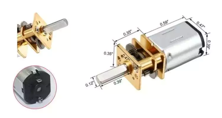
planetary gearboxes
A planetary gearbox is a type of drivetrain in which the input and output shafts are connected with a planetary structure. A planetary gearset can have three main components: an input gear, a planetary output gear, and a stationary position. Different gears can be used to change the transmission ratios. The planetary structure arrangement gives the planetary gearset high rigidity and minimizes backlash. This high rigidity is crucial for quick start-stop cycles and rotational direction.
Planetary gears need to be lubricated regularly to prevent wear and tear. In addition, transmissions must be serviced regularly, which can include fluid changes. The gears in a planetary gearbox will wear out with time, and any problems should be repaired immediately. However, if the gears are damaged, or if they are faulty, a planetary gearbox manufacturer will repair it for free.
A planetary gearbox is typically a 2-speed design, but professional manufacturers can provide triple and single-speed sets. Planetary gearboxes are also compatible with hydraulic, electromagnetic, and dynamic braking systems. The first step to designing a planetary gearbox is defining your application and the desired outcome. Famous constructors use a consultative modeling approach, starting each project by studying machine torque and operating conditions.
As the planetary gearbox is a compact design, space is limited. Therefore, bearings need to be selected carefully. The compact needle roller bearings are the most common option, but they cannot tolerate large axial forces. Those that can handle high axial forces, such as worm gears, should opt for tapered roller bearings. So, what are the advantages and disadvantages of a helical gearbox?
planetary gear motors
When we think of planetary gear motors, we tend to think of large and powerful machines, but in fact, there are many smaller, more inexpensive versions of the same machine. These motors are often made of plastic, and can be as small as six millimeters in diameter. Unlike their larger counterparts, they have only one gear in the transmission, and are made with a small diameter and small number of teeth.
They are similar to the solar system, with the planets rotating around a sun gear. The planet pinions mesh with the ring gear inside the sun gear. All of these gears are connected by a planetary carrier, which is the output shaft of the gearbox. The ring gear and planetary carrier assembly are attached to each other through a series of joints. When power is applied to any of these members, the entire assembly will rotate.
Compared to other configurations, planetary gearmotors are more complicated. Their construction consists of a sun gear centered in the center and several smaller gears that mesh with the central sun gear. These gears are enclosed in a larger internal tooth gear. This design allows them to handle larger loads than conventional gear motors, as the load is distributed among several gears. This type of motor is typically more expensive than other configurations, but can withstand the higher-load requirements of some machines.
Because they are cylindrical in shape, planetary gear motors are incredibly versatile. They can be used in various applications, including automatic transmissions. They are also used in applications where high-precision and speed are necessary. Furthermore, the planetary gear motor is robust and is characterized by low vibrations. The advantages of using a planetary gear motor are vast and include: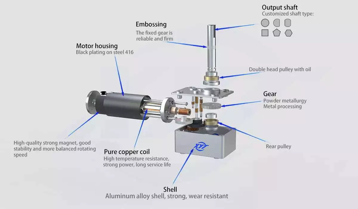
planetary gears vs spur gears
A planetary motor uses multiple teeth to share the load of rotating parts. This gives planetary gears high stiffness and low backlash – often as low as one or two arc minutes. These characteristics are important for applications that undergo frequent start-stop cycles or rotational direction changes. This article discusses the benefits of planetary gears and how they differ from spur gears. You can watch the animation below for a clearer understanding of how they operate and how they differ from spur gears.
Planetary gears move in a periodic manner, with a relatively small meshing frequency. As the meshing frequency increases, the amplitude of the frequency also increases. The amplitude of this frequency is small at low clearance values, and increases dramatically at higher clearance levels. The amplitude of the frequency is higher when the clearance reaches 0.2-0.6. The amplitude increases rapidly, whereas wear increases slowly after the initial 0.2-0.6-inch-wide clearance.
In high-speed, high-torque applications, a planetary motor is more effective. It has multiple contact points for greater torque and higher speed. If you are not sure which type to choose, you can consult with an expert and design a custom gear. If you are unsure of what type of motor you need, contact Twirl Motor and ask for help choosing the right one for your application.
A planetary gear arrangement offers a number of advantages over traditional fixed-axis gear system designs. The compact size allows for lower loss of effectiveness, and the more planets in the gear system enhances the torque density and capacity. Another benefit of a planetary gear system is that it is much stronger and more durable than its spur-gear counterpart. Combined with its many advantages, a planetary gear arrangement offers a superior solution to your shifting needs.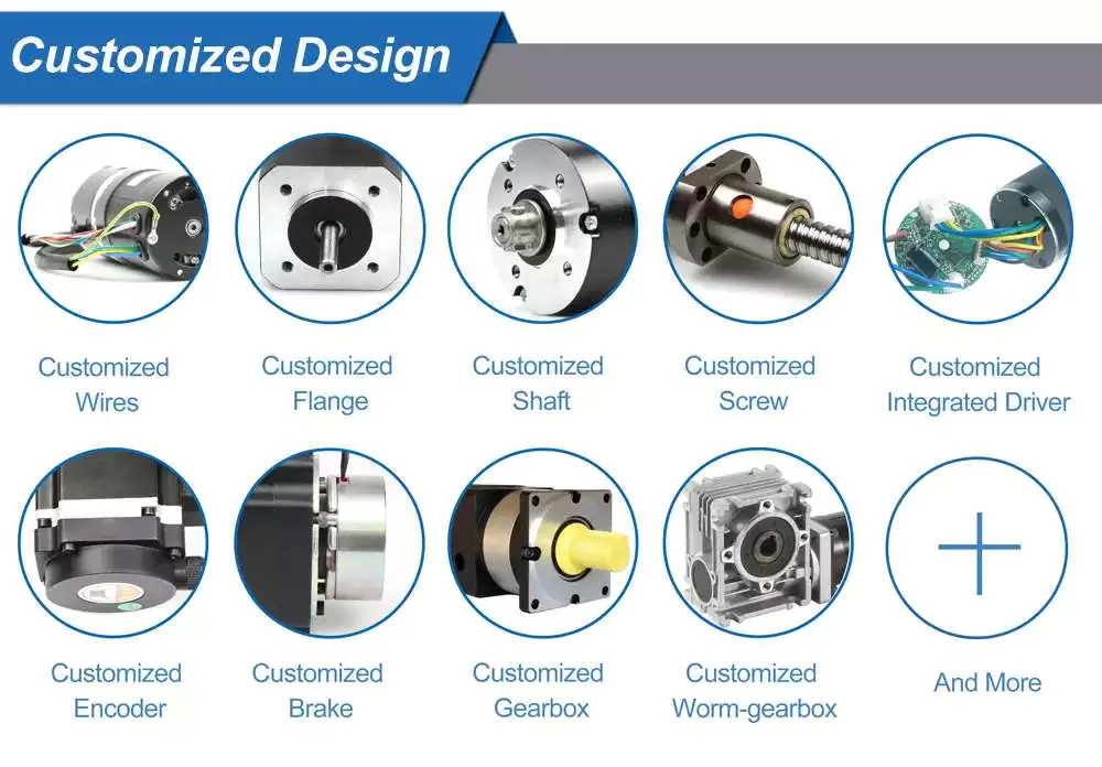
planetary gearboxes as a compact alternative to pinion-and-gear reducers
While traditional pinion-and-gear reducer design is bulky and complex, planetary gearboxes are compact and flexible. They are suitable for many applications, especially where space and weight are issues, as well as torque and speed reduction. However, understanding their mechanism and working isn’t as simple as it sounds, so here are some of the key benefits of planetary gearing.
Planetary gearboxes work by using two planetary gears that rotate around their own axes. The sun gear is used as the input, while the planetary gears are connected via a casing. The ratio of these gears is -Ns/Np, with 24 teeth in the sun gear and -3/2 on the planet gear.
Unlike traditional pinion-and-gear reducer designs, planetary gearboxes are much smaller and less expensive. A planetary gearbox is about 50% smaller and weighs less than a pinion-and-gear reducer. The smaller gear floats on top of three large gears, minimizing the effects of vibration and ensuring consistent transmission over time.
Planetary gearboxes are a good alternative to pinion-and-gear drive systems because they are smaller, less complex and offer a higher reduction ratio. Their meshing arrangement is similar to the Milky Way, with the sun gear in the middle and two or more outer gears. They are connected by a carrier that sets their spacing and incorporates an output shaft.
Compared to pinion-and-gear reduces, planetary gearboxes offer higher speed reduction and torque capacity. As a result, planetary gearboxes are small and compact and are often preferred for space-constrained applications. But what about the high torque transfer? If you’re looking for a compact alt

