Product Description
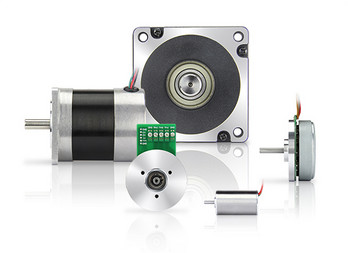
Open loop Nema 17 42mm 2phase 1.8degree 24V 1.2A 0.5N.m torque CHINAMFG electric brushless DC integrated hybrid stepper servo motor
Product Description
FAQ
1. Factory or trader?
–>ZLTECH is a manufacture of hub servo motor, stepper motor, servo motor and driver. We have professional R&D team and factory. 2. How about the delivery?
–> Sample: 7 days.
–> Mass order: 15-30 days.
3. What is your after-sales services?
a. Free maintenance within 12 months guarantee, lifetime consultant.
b. Professional solutions in installation and maintence.
4. Why choose ZLTECH?
–>a. OEM & ODM.
b. Factory Price & 24/7 services.
c. From mold customization to material processing and welding, from fine components to finished assembly, 72 processes, 24 control points, strict aging, finished product inspection.
d. One-stop service, from design to after-sale service.
5. Do you get the relevant certification?
–>All products are made according to ISO9001, CE requirements.
| Application: | CNC Machine |
|---|---|
| Speed: | Low Speed |
| Number of Stator: | Two-Phase |
| Excitation Mode: | HB-Hybrid |
| Function: | Driving |
| Number of Poles: | 50 |
| Samples: |
US$ 32.5/Piece
1 Piece(Min.Order) | |
|---|
| Customization: |
Available
|
|
|---|

How does the speed control of a DC motor work, and what methods are commonly employed?
The speed control of a DC (Direct Current) motor is essential for achieving precise control over its rotational speed. Various methods can be employed to regulate the speed of a DC motor, depending on the specific application requirements. Here’s a detailed explanation of how speed control of a DC motor works and the commonly employed methods:
1. Voltage Control:
One of the simplest methods to control the speed of a DC motor is by varying the applied voltage. By adjusting the voltage supplied to the motor, the electromotive force (EMF) induced in the armature windings can be controlled. According to the principle of electromagnetic induction, the speed of the motor is inversely proportional to the applied voltage. Therefore, reducing the voltage decreases the speed, while increasing the voltage increases the speed. This method is commonly used in applications where a simple and inexpensive speed control mechanism is required.
2. Armature Resistance Control:
Another method to control the speed of a DC motor is by varying the armature resistance. By inserting an external resistance in series with the armature windings, the total resistance in the circuit increases. This increase in resistance reduces the armature current, thereby reducing the motor’s speed. Conversely, reducing the resistance increases the armature current and the motor’s speed. However, this method results in significant power loss and reduced motor efficiency due to the dissipation of excess energy as heat in the external resistance.
3. Field Flux Control:
Speed control can also be achieved by controlling the magnetic field strength of the motor’s stator. By altering the field flux, the interaction between the armature current and the magnetic field changes, affecting the motor’s speed. This method can be accomplished by adjusting the field current through the field windings using a field rheostat or by employing a separate power supply for the field windings. By increasing or decreasing the field flux, the speed of the motor can be adjusted accordingly. This method offers good speed regulation and efficiency but requires additional control circuitry.
4. Pulse Width Modulation (PWM):
Pulse Width Modulation is a widely used technique for speed control in DC motors. It involves rapidly switching the applied voltage on and off at a high frequency. The duty cycle, which represents the percentage of time the voltage is on, is varied to control the effective voltage applied to the motor. By adjusting the duty cycle, the average voltage across the motor is modified, thereby controlling its speed. PWM provides precise speed control, high efficiency, and low power dissipation. It is commonly employed in applications such as robotics, industrial automation, and electric vehicles.
5. Closed-Loop Control:
In closed-loop control systems, feedback from the motor’s speed or other relevant parameters is used to regulate the speed. Sensors such as encoders or tachometers measure the motor’s actual speed, which is compared to the desired speed. The difference, known as the error signal, is fed into a control algorithm that adjusts the motor’s input voltage or other control parameters to minimize the error and maintain the desired speed. Closed-loop control provides excellent speed regulation and accuracy, making it suitable for applications that require precise speed control, such as robotics and CNC machines.
These methods of speed control provide flexibility and adaptability to various applications, allowing DC motors to be effectively utilized in a wide range of industries and systems.
What is the significance of back EMF (electromotive force) in DC motor performance?
The significance of back EMF (electromotive force) in DC motor performance is crucial to understanding the behavior and operation of DC motors. Back EMF is an inherent characteristic of DC motors and plays a pivotal role in their efficiency, speed regulation, and overall performance. Here’s a detailed explanation of the significance of back EMF in DC motor performance:
When a DC motor operates, it generates a voltage known as back EMF or counter electromotive force. This voltage opposes the applied voltage and is caused by the rotation of the motor’s armature within the magnetic field. The back EMF is directly proportional to the rotational speed of the motor.
The significance of back EMF can be understood through the following aspects:
1. Speed Regulation:
Back EMF is crucial for regulating the speed of a DC motor. As the motor rotates faster, the back EMF increases, which reduces the effective voltage across the motor’s armature. Consequently, the armature current decreases, limiting the motor’s speed. This self-regulating characteristic helps maintain a relatively constant speed under varying load conditions. It allows the motor to deliver the required torque while preventing excessive speed that can potentially damage the motor or the driven equipment.
2. Efficiency:
Back EMF plays a significant role in the efficiency of a DC motor. When the motor is loaded and drawing current, the power supplied to the motor is the product of the armature current and the applied voltage. However, the electrical power converted into mechanical power is reduced by the power consumed by the back EMF. The back EMF represents the energy returned to the power supply as the motor generates its own voltage. By reducing the effective voltage across the motor, it helps minimize power losses due to electrical resistance and improves the overall efficiency of the motor.
3. Motor Protection:
The presence of back EMF also provides a level of protection to the motor. When a DC motor is operating and the load on the motor suddenly decreases, such as when the driven equipment is disconnected, the motor’s speed can increase rapidly. This increase in speed leads to a higher back EMF, which reduces the armature current and prevents excessive current flow. By limiting the current, the back EMF helps protect the motor from overloading and potential damage.
4. Voltage Regulation:
Back EMF affects the voltage regulation in a DC motor. When the motor is operating, the back EMF opposes the applied voltage. As the motor load increases, the voltage drop across the armature resistance and other internal losses also increase. The back EMF helps compensate for these voltage drops, ensuring that the motor receives an adequate voltage to maintain its performance and torque output.
5. Control and Dynamic Response:
Back EMF provides valuable information for motor control and dynamic response. By measuring the back EMF voltage, the rotational speed of the motor can be estimated, allowing for precise speed control and feedback. This information is crucial for applications that require accurate speed regulation, such as robotics or industrial automation.
In summary, the significance of back EMF in DC motor performance cannot be overstated. It influences speed regulation, efficiency, motor protection, voltage regulation, and control capabilities. By understanding and utilizing the inherent characteristics of back EMF, engineers can design and optimize DC motor systems for various applications, ensuring reliable and efficient operation.

Are there safety considerations or maintenance practices associated with DC motors?
Yes, there are safety considerations and maintenance practices associated with DC (Direct Current) motors. DC motors, like any other electrical equipment, require proper handling, maintenance, and adherence to safety guidelines to ensure safe operation and longevity. Here’s a detailed explanation of the safety considerations and maintenance practices associated with DC motors:
Safety Considerations:
Electrical Hazards: DC motors operate with high voltages and currents, posing electrical hazards. It is essential to follow proper electrical safety practices, such as wearing appropriate personal protective equipment (PPE) and ensuring that electrical connections are secure and insulated. Proper grounding and isolation techniques should be employed to prevent electrical shocks and accidents.
Lockout/Tagout: DC motors, especially in industrial settings, may require maintenance or repair work. It is crucial to implement lockout/tagout procedures to isolate the motor from its power source before performing any maintenance or servicing activities. This ensures that the motor cannot be accidentally energized during work, preventing potential injuries or accidents.
Overheating and Ventilation: DC motors can generate heat during operation. Adequate ventilation and cooling measures should be implemented to prevent overheating, as excessive heat can lead to motor damage or fire hazards. Proper airflow and ventilation around the motor should be maintained, and any obstructions or debris should be cleared.
Mechanical Hazards: DC motors often have rotating parts and shafts. Safety guards or enclosures should be installed to prevent accidental contact with moving components, mitigating the risk of injuries. Operators and maintenance personnel should be trained to handle motors safely and avoid placing their hands or clothing near rotating parts while the motor is running.
Maintenance Practices:
Cleaning and Inspection: Regular cleaning and inspection of DC motors are essential for their proper functioning. Accumulated dirt, dust, or debris should be removed from the motor’s exterior and internal components. Visual inspections should be carried out to check for any signs of wear, damage, loose connections, or overheating. Bearings, if applicable, should be inspected and lubricated as per the manufacturer’s recommendations.
Brush Maintenance: DC motors that use brushes for commutation require regular inspection and maintenance of the brushes. The brushes should be checked for wear, proper alignment, and smooth operation. Worn-out brushes should be replaced to ensure efficient motor performance. Brush holders and springs should also be inspected and cleaned as necessary.
Electrical Connections: The electrical connections of DC motors should be periodically checked to ensure they are tight, secure, and free from corrosion. Loose or damaged connections can lead to voltage drops, overheating, and poor motor performance. Any issues with the connections should be addressed promptly to maintain safe and reliable operation.
Insulation Testing: Insulation resistance testing should be performed periodically to assess the condition of the motor’s insulation system. This helps identify any insulation breakdown or degradation, which can lead to electrical faults or motor failures. Insulation resistance testing should be conducted following appropriate safety procedures and using suitable testing equipment.
Alignment and Balance: Proper alignment and balance of DC motors are crucial for their smooth operation and longevity. Misalignment or imbalance can result in increased vibrations, excessive wear on bearings, and reduced motor efficiency. Regular checks and adjustments should be made to ensure the motor is correctly aligned and balanced as per the manufacturer’s specifications.
Manufacturer’s Recommendations: It is important to refer to the manufacturer’s guidelines and recommendations for specific maintenance practices and intervals. Each DC motor model may have unique requirements, and following the manufacturer’s instructions ensures that maintenance is carried out correctly and in accordance with the motor’s design and specifications.
By adhering to safety considerations and implementing proper maintenance practices, DC motors can operate safely, reliably, and efficiently throughout their service life.


editor by CX 2023-11-30
China Standard NEMA17 with 60mm Body Length Planetary Gearbox Stepper Motor with Cheap Price wholesaler
Product Description
Nema17 with 60mm body length planetary gearbox stepper motor with cheap price
General Specification:
Step Angle Accuracy: ±5%
Resistance Accuracy: ±10%
Inductance Accuracy: ±20%
Temperature Rise: 80°C Max
Ambient Temperature: -20°C~+50°C
Insulation Resistance: 100MΩ Min., 500VDC
Dielectric Strength: 1800VAC for 1 second 5mA
Shaft Radial Play: 0.02Max (450g-load)
Shaft Axial Play: 0.08Max (450g-load)
Specification:
| Model No. | Step Angle | Motor Length | Current /Phase |
Resistance /Phase |
Inductance /Phase |
Holding Torque | # of Leads | Mass |
| ( °) | (L)mm | A | Ω | mH | kg.cm | No. | Kg | |
| JK42HS60-1704 | 1.8 | 60 | 1.7 | 3.0 | 6.2 | 7.3 | 4 | 0.6 |
Applications:
Used for robots stepper motor,
electronic automatic equipment stepping motor,
medical instrument stepping motor,
advertising instrument stepper motor,
lighting& audio equipment stepper motor,
printer stepper motor, textile machinery stepper motor.
Cnc router stepper motor.
| Application: | CNC Machine |
|---|---|
| Speed: | Low Speed |
| Number of Stator: | Two-Phase |
| Excitation Mode: | HB-Hybrid |
| Function: | Driving |
| Number of Poles: | 2 |
| Customization: |
Available
| Customized Request |
|---|

The Basics of a Gear Motor
The basic mechanism behind the gear motor is the principle of conservation of angular momentum. The smaller the gear, the more RPM it covers and the larger the gear, the more torque it produces. The ratio of angular velocity of two gears is called the gear ratio. Moreover, the same principle applies to multiple gears. This means that the direction of rotation of each adjacent gear is always the opposite of the one it is attached to.
Induction worm gear motor
If you’re looking for an electric motor that can deliver high torque, an Induction worm gear motor might be the right choice. This type of motor utilizes a worm gear attached to the motor to rotate a main gear. Because this type of motor is more efficient than other types of motors, it can be used in applications requiring massive reduction ratios, as it is able to provide more torque at a lower speed.
The worm gear motor is designed with a spiral shaft that is set into splines in another gear. The speed at which the worm gear rotates is dependent on the torque produced by the main gear. Induction worm gear motors are best suited for use in low-voltage applications such as electric cars, renewable energy systems, and industrial equipment. They come with a wide range of power-supply options, including twelve-volt, 24-volt, and 36-volt AC power supplies.
These types of motors can be used in many industrial settings, including elevators, airport equipment, food packaging facilities, and more. They also produce less noise than other types of motors, which makes them a popular choice for manufacturers with limited space. The efficiency of worm gearmotors makes them an excellent choice for applications where noise is an issue. Induction worm gear motors can be compact and extremely high-torque.
While the Induction worm gear motor is most widely used in industrial applications, there are other kinds of gearmotors available. Some types are more efficient than others, and some are more expensive than others. For your application, choosing the correct motor and gearbox combination is crucial to achieving the desired result. You’ll find that the Induction worm gear motor is an excellent choice for many applications. The benefits of an Induction worm gear motor can’t be overstated.
The DC gear motor is an excellent choice for high-end industrial applications. This type of gearmotor is smaller and lighter than a standard AC motor and can deliver up to 200 watts of torque. A gear ratio of three to two can be found in these motors, which makes them ideal for a wide range of applications. A high-quality DC gear motor is a great choice for many industrial applications, as they can be highly efficient and provide a high level of reliability.
Electric gear motors are a versatile and widely used type of electric motor. Nevertheless, there are some applications that don’t benefit from them, such as applications with high shaft speed and low torque. Applications such as fan motors, pump and scanning machines are examples of such high-speed and high-torque demands. The most important consideration when choosing a gearmotor is its efficiency. Choosing the right size will ensure the motor runs efficiently at peak efficiency and will last for years.
Parallel shaft helical gear motor
The FC series parallel shaft helical gearmotor is a compact, lightweight, and high-performance unit that utilizes a parallel shaft structure. Its compact design is complemented by high transmission efficiency and high carrying capacity. The motor’s material is 20CrMnTi alloy steel. The unit comes with either a flanged input or bolt-on feet for installation. Its low noise and compact design make it an ideal choice for a variety of applications.
The helical gears are usually arranged in two rows of one another. Each row contains one or more rows of teeth. The parallel row has the teeth in a helical pattern, while the helical rows are lined up parallelly. In addition to this, the cross helical gears have a point contact design and do not overlap. They can be either parallel or crossed. The helical gear motors can have any number of helical pairs, each with a different pitch circle diameter.
The benefits of the Parallel Shaft Helical Gearbox include high temperature and pressure handling. It is produced by skilled professionals using cutting-edge technology, and is widely recognized for its high performance. It is available in a range of technical specifications and is custom-made to suit individual requirements. These gearboxes are durable and low-noise and feature high reliability. You can expect to save up to 40% of your energy by using them.
The parallel shaft helical gear motors are designed to reduce the speed of a rotating part. The nodular cast iron housing helps make the unit robust in difficult environments, while the precision-machined gears provide quiet, vibration-free operation. These motors are available in double reduction, triple reduction, and quadruple reduction. The capacity ranges from 0.12 kW to 45 kW. You can choose from a wide variety of capacities, depending on the size of your gearing needs.
The SEW-EURODRIVE parallel shaft helical gearmotor is a convenient solution for space-constrained applications. The machine’s modular design allows for easy mounting and a wide range of ambient temperatures. They are ideal for a variety of mechanical applications, including conveyors, augers, and more. If you want a small footprint, the SEW-EURODRIVE parallel shaft helical gear motor is the best solution for you.
The parallel shaft helical gears are advantageous for both high and low speed applications. Parallel helical gears are also suitable for low speed and low duty applications. A good example of a cross-helix gear is the oil pump of an internal combustion engine. Both types of helical gears are highly reliable and offer vibration-free operation. They are more costly than conventional gear motors, but offer more durability and efficiency.
Helical gear unit
This helical gear unit is designed to operate under a variety of demanding conditions and can be used in a wide range of applications. Designed for long life and high torque density, this gear unit is available in a variety of torques and gear ratios. Its design and construction make it compatible with a wide range of critical mechanical systems. Common applications include conveyors, material handling, steel mills, and paper mills.
Designed for high-performance applications, the Heidrive helical gear unit provides superior performance and value. Its innovative design allows it to function well under a wide range of operating conditions and is highly resistant to damage. These gear motors can be easily combined with a helical gear unit. Their combined power output is 100 Nm, and they have a high efficiency of up to 90%. For more information about the helical gear motor, contact a Heidrive representative.
A helical gear unit can be classified by its reference section in the standard plane or the turning plane. Its center gap is the same as that of a spur gear, and its number of teeth is the same. In addition to this, the helical gear has a low axial thrust, which is another important characteristic. The helical gear unit is more efficient at transferring torque than a spur gear, and it is quieter, too.
These units are designed to handle large loads. Whether you are using them for conveyors, augers, or for any other application that involves high-speed motion, a helical gear unit will deliver maximum performance. A helical gear unit from Flender can handle 400,000 tasks with a high degree of reliability. Its high efficiency and high resistance to load ensures high plant availability. These gear motors are available in a variety of sizes, from single-speed to multi-speed.
PEC geared motors benefit from decades of design experience and high quality materials. They are robust, quiet, and offer excellent performance. They are available in multiple configurations and are dimensionally interchangeable with other major brands. The gear motors are manufactured as modular kits to minimize inventory. They can be fitted with additional components, such as backstops and fans. This makes it easy to customize your gear motors and save money while reducing costs.
Another type of helical gears is the double helical gear. The double helical gear unit has two helical faces with a gap between them. They are better for enclosed gear systems as they provide greater tooth overlap and smoother performance. Compared to double helical gears, they are smaller and more flexible than the Herringbone type. So, if you’re looking for a gear motor, a helical gear unit may be perfect for you.
editor by CX 2023-05-19
China OEM 3V 4mm Low Noise Planetary Gear Stepper Motor with Gearbox wholesaler
Product Description
3V 4mm Low Noise Planetary gear stepper motor With gearbox
Product Description
1)Specification
Gearbox Specifications:
| Outer diameter | 3mm |
| Material | Metal |
| Direction of rotation | cc&ccw |
| Gear backlash | ≤3° |
| Bearing | Porous Bearing |
| Axial endplay | ≤0.3mm |
| Radial loading on output shaft | ≤0.3N |
| Operating temperature range | -20…+80ºC |
| Gearbox stages: | 1 | 2 | 3 | 4 |
| Reduction Ratio | 5 | 25 | 125 | 625 |
| Max Rated Torque (gf.cm max) | 50 | 50 | 50 | 50 |
| Max Instant Torque (gf.cm max) | 150 | 150 | 150 | 150 |
| Gearbox efficiency | 85 | 73 | 65 | 58 |
| Length | 6 | 7.5 | 9 | 10.5 |
Motor specifications:
| Motors(Optional) | Stepper motor, coreless motor |
| Voltage(Optional) | 1.5-5V |
| Input speed | ≤10000rpm |
| Current | 50MA max |
Performance Data:
| Model | Application Parameters | Rated Torque of Gear Box | Instant Torque of Gear Box | Gear Ratio | Gear Box Length L1 |
|||||
| Rated | Speed at 500 pps 500pps |
Current | At Rated Load | Overall Length L |
||||||
| Voltage | Stall Torque | |||||||||
| VDC | rpm | mA | gf.cm | mN.m | mm | gf.cm | gf.cm | mm | ||
| ZWBMD004004-5 | 3.0 | 300.0 | 340.0 | 2.0 | 0.20 | 10.75 | 70 | 200 | 5 | 6.0 |
| ZWBMD004004-25 | 3.0 | 60.0 | 340.0 | 9.5 | 0.93 | 12.25 | 70 | 200 | 25 | 7.5 |
| ZWBMD004004-125 | 3.0 | 12.0 | 340.0 | 40 | 3.92 | 13.75 | 70 | 200 | 125 | 9.0 |
| ZWBMD004004-625 | 3.0 | 2.4 | 340.0 | 170 | 16.67 | 15.25 | 70 | 200 | 625 | 10.5 |
above specifications just for reference and customizable according to requirements.
Integrated Drive Control Module.
Please let us know your requirements and we will provide you with micro transmission solutions.
2)2D Drawing
Detailed Photos
Application
| Smart wearable devices | watch,VR,AR,XR and etc. |
| Household application | kitchen appliances, sewing machines, corn popper, vacuum cleaner, garden tool, sanitary ware, window curtain, intelligent closestool, sweeping robot, power seat, standing desk, electric sofa, TV, computer, treadmill, spyhole, cooker hood, electric drawer, electric mosquito net, intelligent cupboard, intelligent wardrobe, automatic soap dispenser, UV baby bottle sterilizer, lifting hot pot cookware, dishwasher, washing machine, food breaking machine, dryer, air conditioning, dustbin, coffee machine, whisk,smart lock,bread maker,Window cleaning robot and etc. |
| communication equipment | 5G base station,video conference,mobile phone and etc. |
| Office automation equipments | scanners, printers, multifunction machines copy machines, fax (FAX paper cutter), computer peripheral, bank machine, screen, lifting socket, display,notebook PC and etc. |
| Automotive products | conditioning damper actuator, car DVD,door lock actuator, retractable rearview mirror, meters, optic axis control device, head light beam level adjuster, car water pump, car antenna, lumbar support, EPB, car tail gate electric putter, HUD, head-up display, vehicle sunroof, EPS, AGS, car window, head restraint, E-booster, car seat, vehicle charging station and etc. |
| Toys and models | radio control model, automatic cruise control, ride-on toy, educational robot, programming robot, medical robot, automatic feeder, intelligent building blocks, escort robot and etc. |
| Medical equipments | blood pressure meter, breath machine, medical cleaning pump, medical bed, blood pressure monitors, medical ventilator, surgical staplers, infusion pump, dental instrument, self-clotting cutter, wound cleaning pump for orthopedic surgery,electronic cigarette, eyebrow pencil,fascia gun, , surgical robot,laboratory automation and etc. |
| Industrials | flow control valves, seismic testing,automatic reclosing,Agricultural unmanned aerial vehicle,automatic feeder ,intelligent express cabinet and etc. |
| Electric power tools | electric drill, screwdriver,garden tool and etc. |
| Precision instruments | optics instruments,automatic vending machine, wire-stripping machine and etc. |
| Personal care | tooth brush, hair clipper, electric shaver, massager, vibrator, hair dryer, rubdown machine, scissor hair machine, foot grinder,anti-myopia pen, facial beauty equipment, hair curler,Electric threading knife,POWER PERFECT PORE, Puff machine,eyebrow tweezers and etc. |
| Consumer electronics | camera, mobile phone,digital camera, automatic retracting device,camcorder, kinescope DVD,headphone stereo, cassette tape recorder, bluetooth earbud charging case, turntable, tablet,UAV(unmanned aerial vehicle),surveillance camera,PTZ camera, rotating smart speaker and etc. |
| robots | educational robot, programming robot, medical robot, escort robot and etc. |
Company Profile
HangZhou CZPT Machinery & Electronics Co., Ltd was established in 2001,We provide the total drive solution for customers from design, tooling fabrication, components manufacturing and assembly.
Workshop
Testing Equipment
1) Competitive Advantages
- 1) Competitive Advantages
19+year experience in manufacturing motor gearbox
We provide technical support from r&d, prototype, testing, assembly and serial production , ODM &OEM
Competitive Price
Product Performance: Low noise, High efficiency, Long lifespan
Prompt Delivery: 15 working days after payment
Small Orders Accepted
2) Main Products
-
Precision reduction gearbox and its diameter:3.4mm-38mm,voltage:1.5-24V,power: 0.01-40W,output speed:5-2000rpm and output torque:1.0 gf.cm -50kgf.cm,
- Customized worm and gear transmission machinery;
- Precise electromechanical motion module;
- Precise component and assembly of plastic and metal powder injection.
Our Services
- ODM & OEM
- Gearbox design and development
- Related technology support
- Micro drive gearbox custom solution
Packaging & Shipping
1) Packing Details
packed in nylon firstly, then carton, and then reinforced with wooden case for outer packing.
Or according to client’s requirement.
2) Shipping Details
samples will be shipped within 10 days;
batch order leading time according to the actual situation.
Certifications
Certifications
We Have passed to hold ISO9001:2015(CN11/3571),ISO14001:2004(U006616E0153R3M), ISO13485:2016(CN18/42018) and IATF16949:2016(CN11/3571.01).
and more…
FAQ
FAQ
1. Can you make the gearbox with custom specifications?
YES. We have design and development team, also a great term of engineers, each of them have
many work years experience.
2.Do you provide the samples?
YES. Our company can provide the samples to you, and the delivery time is about 5-15days according to the specification of gearbox you need.
3.What is your MOQ?
Our MOQ is 2000pcs. But at the beginning of our business, we accept small order.
4. Do you have the item in stock?
I am sorry we donot have the item in stock, All products are made with orders.
5. Do you provide technology support?
YES. Our company have design and development team, we can provide technology support if you
need.
6.How to ship to us?
We will ship the goods to you according to the DHL or UPS or FEDEX etc account you provide.
7.How to pay the money?
We accept T/T in advance. Also we have different bank account for receiving money, like US dollors or RMB etc.
8. How can I know the product is suitable for me?
Frist, you need to provide us the more details information about the product. We will recommend the item to you according to your requirement of specification. After you confirm, we will prepare the samples to you. also we will offer some good advances according to your product use.
9. Can I come to your company to visit?
YES, you can come to our company to visit at anytime, and welcome to visit our company.
10. How do contact us ?
Please send an inquiry
| Application: | Universal, Industrial, Household Appliances, Car, Power Tools, Precise Instrument |
|---|---|
| Operating Speed: | Low Speed |
| Excitation Mode: | Permanent Magnet |
| Function: | Control |
| Casing Protection: | Drip-Proof |
| Number of Poles: | Customize |
| Samples: |
US$ 90/Piece
1 Piece(Min.Order) | |
|---|
| Customization: |
Available
| Customized Request |
|---|
Dynamic Modeling of a Planetary Motor
A planetary gear motor consists of a series of gears rotating in perfect synchrony, allowing them to deliver torque in a higher output capacity than a spur gear motor. Unlike the planetary motor, spur gear motors are simpler to build and cost less, but they are better for applications requiring lower torque output. That is because each gear carries the entire load. The following are some key differences between the two types of gearmotors.
planetary gear system
A planetary gear transmission is a type of gear mechanism that transfers torque from one source to another, usually a rotary motion. Moreover, this type of gear transmission requires dynamic modeling to investigate its durability and reliability. Previous studies included both uncoupled and coupled meshing models for the analysis of planetary gear transmission. The combined model considers both the shaft structural stiffness and the bearing support stiffness. In some applications, the flexible planetary gear may affect the dynamic response of the system.
In a planetary gear device, the axial end surface of the cylindrical portion is rotatable relative to the separating plate. This mechanism retains lubricant. It is also capable of preventing foreign particles from entering the planetary gear system. A planetary gear device is a great choice if your planetary motor’s speed is high. A high-quality planetary gear system can provide a superior performance than conventional systems.
A planetary gear system is a complex mechanism, involving three moving links that are connected to each other through joints. The sun gear acts as an input and the planet gears act as outputs. They rotate about their axes at a ratio determined by the number of teeth on each gear. The sun gear has 24 teeth, while the planet gears have three-quarters that ratio. This ratio makes a planetary motor extremely efficient.
planetary gear train
To predict the free vibration response of a planetary motor gear train, it is essential to develop a mathematical model for the system. Previously, static and dynamic models were used to study the behavior of planetary motor gear trains. In this study, a dynamic model was developed to investigate the effects of key design parameters on the vibratory response. Key parameters for planetary gear transmissions include the structure stiffness and mesh stiffness, and the mass and location of the shaft and bearing supports.
The design of the planetary motor gear train consists of several stages that can run with variable input speeds. The design of the gear train enables the transmission of high torques by dividing the load across multiple planetary gears. In addition, the planetary gear train has multiple teeth which mesh simultaneously in operation. This design also allows for higher efficiency and transmittable torque. Here are some other advantages of planetary motor gear trains. All these advantages make planetary motor gear trains one of the most popular types of planetary motors.
The compact footprint of planetary gears allows for excellent heat dissipation. High speeds and sustained performances will require lubrication. This lubricant can also reduce noise and vibration. But if these characteristics are not desirable for your application, you can choose a different gear type. Alternatively, if you want to maintain high performance, a planetary motor gear train will be the best choice. So, what are the advantages of planetary motor gears?
planetary gear train with fixed carrier train ratio
The planetary gear train is a common type of transmission in various machines. Its main advantages are high efficiency, compactness, large transmission ratio, and power-to-weight ratio. This type of gear train is a combination of spur gears, single-helical gears, and herringbone gears. Herringbone planetary gears have lower axial force and high load carrying capacity. Herringbone planetary gears are commonly used in heavy machinery and transmissions of large vehicles.
To use a planetary gear train with a fixed carrier train ratio, the first and second planets must be in a carrier position. The first planet is rotated so that its teeth mesh with the sun’s. The second planet, however, cannot rotate. It must be in a carrier position so that it can mesh with the sun. This requires a high degree of precision, so the planetary gear train is usually made of multiple sets. A little analysis will simplify this design.
The planetary gear train is made up of three components. The outer ring gear is supported by a ring gear. Each gear is positioned at a specific angle relative to one another. This allows the gears to rotate at a fixed rate while transferring the motion. This design is also popular in bicycles and other small vehicles. If the planetary gear train has several stages, multiple ring gears may be shared. A stationary ring gear is also used in pencil sharpener mechanisms. Planet gears are extended into cylindrical cutters. The ring gear is stationary and the planet gears rotate around a sun axis. In the case of this design, the outer ring gear will have a -3/2 planet gear ratio.
planetary gear train with zero helix angle
The torque distribution in a planetary gear is skewed, and this will drastically reduce the load carrying capacity of a needle bearing, and therefore the life of the bearing. To better understand how this can affect a gear train, we will examine two studies conducted on the load distribution of a planetary gear with a zero helix angle. The first study was done with a highly specialized program from the bearing manufacturer INA/FAG. The red line represents the load distribution along a needle roller in a zero helix gear, while the green line corresponds to the same distribution of loads in a 15 degree helix angle gear.
Another method for determining a gear’s helix angle is to consider the ratio of the sun and planet gears. While the sun gear is normally on the input side, the planet gears are on the output side. The sun gear is stationary. The two gears are in engagement with a ring gear that rotates 45 degrees clockwise. Both gears are attached to pins that support the planet gears. In the figure below, you can see the tangential and axial gear mesh forces on a planetary gear train.
Another method used for calculating power loss in a planetary gear train is the use of an auto transmission. This type of gear provides balanced performance in both power efficiency and load capacity. Despite the complexities, this method provides a more accurate analysis of how the helix angle affects power loss in a planetary gear train. If you’re interested in reducing the power loss of a planetary gear train, read on!
planetary gear train with spur gears
A planetary gearset is a type of mechanical drive system that uses spur gears that move in opposite directions within a plane. Spur gears are one of the more basic types of gears, as they don’t require any specialty cuts or angles to work. Instead, spur gears use a complex tooth shape to determine where the teeth will make contact. This in turn, will determine the amount of power, torque, and speed they can produce.
A two-stage planetary gear train with spur gears is also possible to run at variable input speeds. For such a setup, a mathematical model of the gear train is developed. Simulation of the dynamic behaviour highlights the non-stationary effects, and the results are in good agreement with the experimental data. As the ratio of spur gears to spur gears is not constant, it is called a dedendum.
A planetary gear train with spur gears is a type of epicyclic gear train. In this case, spur gears run between gears that contain both internal and external teeth. The circumferential motion of the spur gears is analogous to the rotation of planets in the solar system. There are four main components of a planetary gear train. The planet gear is positioned inside the sun gear and rotates to transfer motion to the sun gear. The planet gears are mounted on a joint carrier that is connected to the output shaft.
planetary gear train with helical gears
A planetary gear train with helical teeth is an extremely powerful transmission system that can provide high levels of power density. Helical gears are used to increase efficiency by providing a more efficient alternative to conventional worm gears. This type of transmission has the potential to improve the overall performance of a system, and its benefits extend far beyond the power density. But what makes this transmission system so appealing? What are the key factors to consider when designing this type of transmission system?
The most basic planetary train consists of the sun gear, planet gear, and ring gear elements. The number of planets varies, but the basic structure of planetary gears is similar. A simple planetary geartrain has the sun gear driving a carrier assembly. The number of planets can be as low as two or as high as six. A planetary gear train has a low mass inertia and is compact and reliable.
The mesh phase properties of a planetary gear train are particularly important in designing the profiles. Various parameters such as mesh phase difference and tooth profile modifications must be studied in depth in order to fully understand the dynamic characteristics of a PGT. These factors, together with others, determine the helical gears’ performance. It is therefore essential to understand the mesh phase of a planetary gear train to design it effectively.
editor by CX 2023-05-08
China Professional NEMA24 High Precision Economy Hybrid Geared Stepper Motor with Planetary Gear Reducer with Hot selling
Product Description
Product Description
Planetary Gear Stepping Motor :
Precision high-end upgrade with Nema8, Nema 11, Nema14, Nema 17, Nema23, Nema 24
stepper motor; low noise, low vibration, firm and durable. Increase torque at low speed.
Reduction ratio:1:3.7 , 1:5.2 , 1:14 , 1:19 ,1:27 ,1:51 , 1:71 ,1:100 ,1:139 , 1:189 ,1:264 , 1:369 ,And 48 hours delivery , in stock .
Application:
Automation control, medical equipment, textile machinery,and packaging machinery fields. Not only in the field of the automation industry, it also has a good use status in the home. Products with low speed and inertia are often seen: electric curtains, electric shutters, etc
Product Parameters
Planetary Gear Box Specification:
| Housing Material | Metal |
| Bearing at Output | Ball Bearings |
| Max.Radial Load(10mm from flange) | 300N |
| Max.Shaft Axial Load | 200N |
| Radial Play of Shaft (near to Flange) | ≤0.08mm |
| Axial Play of Shaft | ≤0.4mm |
| Backlash at No-load | 1 stage≤1°,2stage≤1.2°,3stage≤1.5° |
60HS Hybrid Stepping Motor Specifications:
| Model No. | Step Angle | Motor Length(L1) | Rated | Current | Resistance | Inductance | Holding Torque | # of Leads | Rotor Inertia | Mass | Max.Gear Ratio |
| Voltage | /Phase | /Phase | /Phase | ||||||||
| Single Shaft | ( °) | (L)mm | V | A | Ω | mH | mN.m | No. | g.cm2 | Kg | |
| 60HS5405 | 1.8 | 55 | 2.98 | 3.5 | 0.85 | 3 | 1900 | 4 | 300 | 0.7 | ≤1:187 |
| 60HS5405 Planetary Gearbox Specifications: | ||||||||||||||
| Reduction ratio | 3.6 | 4.25 | 13 | 15 | 18 | 23 | 47 | 55 | 65 | 77 | 96 | 121 | 153 | 187 |
| Total Height(L1+L2) (mm) | 92.8 | 92.8 | 104.4 | 104.4 | 104.4 | 104.4 | 115.8 | 115.8 | 115.8 | 115.8 | 115.8 | 115.8 | 126.9 | 126.9 |
| Output torque ( mN.m) | 6156 | 7268 | 15000 | 15000 | 15000 | 15000 | 30000 | 30000 | 30000 | 30000 | 30000 | 30000 | 30000 | 30000 |
| Total Weight(g) | 1200 | 1200 | 1388 | 1388 | 1388 | 1388 | 1576 | 1576 | 1576 | 1576 | 1576 | 1576 | 1620 | 1620 |
| Number of gear trains | 1 | 2 | 3 | 4 | ||||||||||
| Reducer Length(L2) (mm) | 37.8 | 49.4 | 60.8 | 71.9 | ||||||||||
| Efficiency | 90% | 81% | 73% | 66% | ||||||||||
Detailed Photos
Company Profile
ZheJiang UMot Technology Co., Ltd. specializes in R&D and sales of stepper motors, servo motors, linear modules and related motion control products, customizing and designing high-quality motor products for users with special needs around the world, and providing overall solutions for motion control systems. Products are exported to more than 30 countries and regions including the United States, Germany, France, Italy, Russia, and Switzerland. The company’s main products and system design have been widely used in automation control, precision instruments, medical equipment, smart home, 3D printing and many other fields.
Our company has been recognized as a high-tech enterprise by relevant departments, has a complete quality management system, has obtained ISO9001, CE, RoHs and other related certifications, and holds a number of electrical patent certificates. “Concentration, Professionalism, Concentration” in the field of automation of motor R&D and system control solutions is the company’s business purpose. “Be your most trusted partner” is the company’s service philosophy. We have always been aiming to “make first-class products with professional technology”, keep pace with the times, innovate constantly, and provide more users with better products and services.
FAQ
1. Shipping method:
1)International Express delivery DHL&FEDEX &UPS&TNT& 7-10days
2)Shipping by air 7-10 days
3)shipping by sea, delivery time depends on the destination port.
2. Technical Support:
We can provide you with professional technical support. And our products quality guarantee is 6 months. Also, we accept products customized.
3. Why should you buy from us, not from other suppliers?
Professional one-to-1 motor customized. The world’s large enterprise of choice for high-quality suppliers. ISO9001:2008 quality management system certification, through the CE, ROHS certification.
4. How to select models?
Before purchasing, please contact us to confirm model No. and specifications to avoid any misunderstanding.
5. Are you a factory?
Yes, we are a factory, and we produce stepper motor/driver, Servo motor/driver.
| Application: | Automation Control, Medical Equipment, Textile Mac |
|---|---|
| Speed: | Low Speed |
| Number of Stator: | Two-Phase |
| Excitation Mode: | HB-Hybrid |
| Function: | Control, Driving |
| Number of Poles: | 2 |
| Samples: |
US$ 65.0/Piece
1 Piece(Min.Order) | |
|---|
| Customization: |
Available
| Customized Request |
|---|

The Benefits of Using a Gear Motor
A gear motor works on the principle of conservation of angular momentum. As the smaller gear covers more RPM and the larger gear produces more torque, the ratio between the two is greater than one. Similarly, a multiple gear motor follows the principle of energy conservation, with the direction of rotation always opposite to the one that is adjacent to it. It’s easy to understand the concept behind gear motors and the various types available. Read on to learn about the different types of gears and their applications.
Electric motor
The choice of an electric motor for gear motor is largely dependent on the application. There are various motor and gearhead combinations available, and some are more efficient than others. However, it is critical to understand the application requirements and select a motor that meets these needs. In this article, we’ll examine some of the benefits of using a gear motor. The pros and cons of each type are briefly discussed. You can buy new gear motors at competitive prices, but they aren’t the most reliable or durable option for your application.
To determine which motor is best for your application, you’ll need to consider the load and speed requirements. A gear motor’s efficiency (e) can be calculated by taking the input and output values and calculating their relation. On the graph below, the input (T) and output (P) values are represented as dashed lines. The input (I) value is represented as the torque applied to the motor shaft. The output (P) is the amount of mechanical energy converted. A DC gear motor is 70% efficient at 3.75 lb-in / 2,100 rpm.
In addition to the worm gear motor, you can also choose a compact DC worm gear motor with a variable gear ratio from 7.5 to 80. It has a range of options and can be custom-made for your specific application. The 3-phase AC gear motor, on the other hand, works at a rated power of one hp and torque of 1.143.2 kg-m. The output voltage is typically 220V.
Another important factor is the output shaft orientation. There are two main orientations for gearmotors: in-line and offset. In-line output shafts are most ideal for applications with high torque and short reduction ratios. If you want to avoid backlash, choose a right angle output shaft. An offset shaft can cause the output shaft to become excessively hot. If the output shaft is angled at a certain angle, it may be too large or too small.
Gear reducer
A gear reducer is a special kind of speed reducing motor, usually used in large machinery, such as compressors. These reducers have no cooling fan and are not designed to handle heavy loads. Different purposes require different service factors. For instance, a machine that requires frequent fast accelerations and occasional load spikes needs a gear reducer with a high service factor. A gear reducer that’s designed for long production shifts should be larger than a machine that uses it for short periods of time.
A gear reducer can reduce the speed of a motor by a factor of two. The reduction ratio changes the rotation speed of the receiving member. This change in speed is often required to solve problems of inertia mismatch. The torque density of a gear reducer is measured in newton meters and will depend on the motor used. The first criterion is the configuration of the input and output shafts. A gear ratio of 2:1, for example, means that the output speed has been cut in half.
Bevel gear reducers are a good option if the input and output shafts are perpendicular. This type is very robust and is perfect for situations where the angle between two axes is small. However, bevel gear reducers are expensive and require constant maintenance. They are usually used in heavy-duty conveyors and farm equipment. The correct choice of gear reducer for gear motor is crucial for the efficiency and reliability of the mechanism. To get the best gear reducer for your application, talk to a qualified manufacturer today.
Choosing a gear reducer for a gear motor can be tricky. The wrong one can ruin an entire machine, so it’s important to know the specifics. You must know the torque and speed requirements and choose a motor with the appropriate ratio. A gear reducer should also be compatible with the motor it’s intended for. In some cases, a smaller motor with a gear reducer will work better than a larger one.
Motor shaft
Proper alignment of the motor shaft can greatly improve the performance and life span of rotating devices. The proper alignment of motors and driven instruments enhances the transfer of energy from the motor to the instrument. Incorrect alignment leads to additional noise and vibration. It may also lead to premature failure of couplings and bearings. Misalignment also results in increased shaft and coupling temperatures. Hence, proper alignment is critical to improve the efficiency of the driven instrument.
When choosing the correct type of gear train for your motor, you need to consider its energy efficiency and the torque it can handle. A helical geared motor is more efficient for high output torque applications. Depending on the required speed and torque, you can choose between an in-line and a parallel helical geared motor. Both types of gears have their advantages and disadvantages. Spur gears are widespread. They are toothed and run parallel to the motor shaft.
A planetary gear motor can also have a linear output shaft. A stepping motor should not operate at too high current to prevent demagnetization, which will lead to step loss or torque drop. Ensure that the motor and gearbox output shafts are protected from external impacts. If the motor and gearbox are not protected against bumps, they may cause thread defects. Make sure that the motor shafts and rotors are protected from external impacts.
When choosing a metal for your gear motor’s motor shaft, you should consider the cost of hot-rolled bar stock. Its outer layers are more difficult to machine. This type of material contains residual stresses and other problems that make it difficult to machine. For these applications, you should choose a high-strength steel with hard outer layers. This type of steel is cheaper, but it also has size considerations. It’s best to test each material first to determine which one suits your needs.
In addition to reducing the speed of your device, a geared motor also minimizes the torque generated by your machine. It can be used with both AC and DC power. A high-quality gear motor is vital for stirring mechanisms and conveyor belts. However, you should choose a geared motor that uses high-grade gears and provides maximum efficiency. There are many types of planetary gear motors and gears on the market, and it’s important to choose the right one.
First stage gears
The first stage gears of a gear motor are the most important components of the entire device. The motor’s power transmission is 90% efficient, but there are many factors that can affect its performance. The gear ratios used should be high enough to handle the load, but not too high that they are limiting the motor’s speed. A gear motor should also have a healthy safety factor, and the lubricant must be sufficient to overcome any of these factors.
The transmission torque of the gear changes with its speed. The transmission torque at the input side of the gear decreases, transferring a small torque to the output side. The number of teeth and the pitch circle diameters can be used to calculate the torque. The first stage gears of gear motors can be categorized as spur gears, helical gears, or worm gears. These three types of gears have different torque capacities.
The first stage helical gear is the most important part of a gear motor. Its function is to transfer rotation from one gear to the other. Its output is the gearhead. The second stage gears are connected by a carrier. They work in tandem with the first stage gear to provide the output of the gearhead. Moreover, the first stage carrier rotates in the same direction as the input pinion.
Another important component is the output torque of the gearmotor. When choosing a gearmotor, consider the starting torque, running torque, output speed, overhung and shock loads, duty cycles, and more. It is crucial to choose a gearmotor with the right ratio for the application. By choosing the proper gearmotor, you will get maximum performance with minimal operating costs and increase plant productivity. For more information on first stage gears, check out our blog.
The first stage of a gear motor is composed of a set of fixed and rotating sprockets. The first stage of these gears acts as a drive gear. Its rotational mass is a limiting factor for torque. The second stage consists of a rotating shaft. This shaft rotates in the direction of the torque axis. It is also the limiting force for the motor’s torque.
editor by CX 2023-04-20
China wholesaler Stepper Motor Stepper Motor Planetary Gearbox Stepper Motor for Automatic Control supplier
Product Description
Product Characteristics
1. Weight: 50g
2. Rated Voltage: 12DCV
3. Operation Frequency: 100pps
4. Step angle: 7.5/85.25
5. Typical Appliances: Refrigerator, Intelligent Sanitary, Automatic Door Lock
| MODEL | VOLTAGE | RESISTANCE | FREQUENCY | TORQUE | STEP ANGLE |
| 30BYJ46 | 12VDC | 110 Ohm | 100PPS | 147N.cm | 7.5º/85.25 |
| 12VDC | 130 Ohm | 100PPS | 78.4N.cm | 7.5º/85.25 | |
| 12VDC | 200 Ohm | 100PPS | 58.8N.cm | 7.5º/85.25 |
ABOUT US
Ritscher group was set up in 2006.we always focus on micro-motors for household electrical appliance and industry appliance since setting up.currently we have 2 professional micro-motor factories in China which severally located in HangZhou city and HangZhou city.it has an area of 25,000 square meters plants and more than 300 employees, annual output is 3 million pcs and has 5 million pcs annual producing capacity.after several years development,we had built a great reputation in the market and got more and more customers’ trust in the world.
We started from shaded pole motors at beginning, up to now,our product included of shaded pole motors,synchronous motors,stepping motors ,capacitor motors, BLDC motors, DC motors and compressors. Our product are widely used for making refrigerators, freezers, micro-wave ovens, air warmers, air exhausters, ventilators,ovens, air filter, massage machines and many other equipments.
As a realiable quality guaranty,Ritscher has complete R&D departement,QC department,producing department,purchase department etc. has perfect producing equipment like Aluminum diecasting, Zinc diecasting, Sheet metal stamping, Plastic injection molding etc. also test/ detection device like multiplex temp measuring device, performance parameter inspection device, Phenol peptide solution pinhole tester,Anechoic room etc.
Endeavoring to provide the best product and service to customers,we always do the most effort to become an outstanding manufacturer of micro motors.
Ritscher is always willing to establish sincere business relationship with friends from all over the world.
Welcome contact with us!
Take CZPT ,enjoy modern life!
Our company FAQ for you
(1) Q: What kind motors you can provide?
A:For now,we mainly provide Kitchen Hood Motor,DC Motor,Gear Motor,Fan Motor Refrigerator Motor,Hair Dryer Motor Blender Motor Mixer Motor,
Shade Pole Motor,Capacitor Motor,BLDC Motor PMDC Motor,Synchronous Motor,Stepping Motor etc.
(2) Q: Is it possible to visit your factory
A: Sure. But please kindly keep us posted a few days in advance. We need to check our
schedule to see if we are available then.
(3) Q: Can I get some samples
A: It depends. If only a few samples for personal use or replacement, I am afraid it will
be difficult for us to provide, because all of our motors are custom made and no stock
available if there is no further needs. If just sample testing before the official order and
our MOQ, price and other terms are acceptable, we’d love to provide samples.
(4) Q: Is there a MOQ for your motors?
A: Yes. The MOQ is between 1000~10,000pcs for different models after sample approval.
But it’s also okay for us to accept smaller lots like a few dozens, hundreds or thousands
For the initial 3 orders after sample approval.For samples, there is no MOQ requirement. But the less the better (like no more than 5pcs) on condition that the quantity is enough in case any changes needed after initial testing.
| Application: | Clocks and Watches |
|---|---|
| Speed: | Variable Speed |
| Number of Stator: | Two-Phase |
| Excitation Mode: | PM-Permanent Magnet |
| Function: | Control, Driving |
| Number of Poles: | 10 |
| Samples: |
US$ 20/Piece
1 Piece(Min.Order) | |
|---|
| Customization: |
Available
| Customized Request |
|---|
What Is a Gear Motor?
A gear motor is an electric motor coupled with a gear train. It uses either DC or AC power to achieve its purpose. The primary benefit of a gear reducer is its ability to multiply torque while maintaining a compact size. The trade-off of this additional torque comes in the form of a reduced output shaft speed and overall efficiency. However, proper gear technology and ratios provide optimum output and speed profiles. This type of motor unlocks the full potential of OEM equipment.
Inertial load
Inertial load on a gear motor is the amount of force a rotating device produces due to its inverse square relationship with its inertia. The greater the inertia, the less torque can be produced by the gear motor. However, if the inertia is too high, it can cause problems with positioning, settling time, and controlling torque and velocity. Gear ratios should be selected for optimal power transfer.
The duration of acceleration and braking time of a gear motor depends on the type of driven load. An inertia load requires longer acceleration time whereas a friction load requires breakaway torque to start the load and maintain it at its desired speed. Too short a time period can cause excessive gear loading and may result in damaged gears. A safe approach is to disconnect the load when power is disconnected to prevent inertia from driving back through the output shaft.
Inertia is a fundamental concept in the design of motors and drive systems. The ratio of mass and inertia of a load to a motor determines how well the motor can control its speed during acceleration or deceleration. The mass moment of inertia, also called rotational inertia, is dependent on the mass, geometry, and center of mass of an object.
Applications
There are many applications of gear motors. They provide a powerful yet efficient means of speed and torque control. They can be either AC or DC, and the two most common motor types are the three-phase asynchronous and the permanent magnet synchronous servomotor. The type of motor used for a given application will determine its cost, reliability, and complexity. Gear motors are typically used in applications where high torque is required and space or power constraints are significant.
There are two types of gear motors. Depending on the ratio, each gear has an output shaft and an input shaft. Gear motors use hydraulic pressure to produce torque. The pressure builds on one side of the motor until it generates enough torque to power a rotating load. This type of motors is not recommended for applications where load reversals occur, as the holding torque will diminish with age and shaft vibration. However, it can be used for precision applications.
The market landscape shows the competitive environment of the gear motor industry. This report also highlights key items, income and value creation by region and country. The report also examines the competitive landscape by region, including the United States, China, India, the GCC, South Africa, Brazil, and the rest of the world. It is important to note that the report contains segment-specific information, so that readers can easily understand the market potential of the geared motors market.
Size
The safety factor, or SF, of a gear motor is an important consideration when selecting one for a particular application. It compensates for the stresses placed on the gearing and enables it to run at maximum efficiency. Manufacturers provide tables detailing typical applications, with multiplication factors for duty. A gear motor with a SF of three or more is suitable for difficult applications, while a gearmotor with a SF of one or two is suitable for relatively easy applications.
The global gear motor market is highly fragmented, with numerous small players catering to various end-use industries. The report identifies various industry trends and provides comprehensive information on the market. It outlines historical data and offers valuable insights on the industry. The report also employs several methodologies and approaches to analyze the market. In addition to providing historical data, it includes detailed information by market segment. In-depth analysis of market segments is provided to help identify which technologies will be most suitable for which applications.
Cost
A gear motor is an electric motor that is paired with a gear train. They are available in AC or DC power systems. Compared to conventional motors, gear reducers can maximize torque while maintaining compact dimensions. But the trade-off is the reduced output shaft speed and overall efficiency. However, when used correctly, a gear motor can produce optimal output and mechanical fit. To understand how a gear motor works, let’s look at two types: right-angle geared motors and inline geared motors. The first two types are usually used in automation equipment and in agricultural and medical applications. The latter type is designed for rugged applications.
In addition to its efficiency, DC gear motors are space-saving and have low energy consumption. They can be used in a number of applications including money counters and printers. Automatic window machines and curtains, glass curtain walls, and banknote vending machines are some of the other major applications of these motors. They can cost up to 10 horsepower, which is a lot for an industrial machine. However, these are not all-out expensive.
Electric gear motors are versatile and widely used. However, they do not work well in applications requiring high shaft speed and torque. Examples of these include conveyor drives, frozen beverage machines, and medical tools. These applications require high shaft speed, so gear motors are not ideal for these applications. However, if noise and other problems are not a concern, a motor-only solution may be the better choice. This way, you can use a single motor for multiple applications.
Maintenance
Geared motors are among the most common equipment used for drive trains. Proper maintenance can prevent damage and maximize their efficiency. A guide to gear motor maintenance is available from WEG. To prevent further damage, follow these maintenance steps:
Regularly check electrical connections. Check for loose connections and torque them to the recommended values. Also, check the contacts and relays to make sure they are not tangled or damaged. Check the environment around the gear motor to prevent dust from clogging the passageway of electric current. A proper maintenance plan will help you identify problems and extend their life. The manual will also tell you about any problems with the gearmotor. However, this is not enough – it is important to check the condition of the gearbox and its parts.
Conduct visual inspection. The purpose of visual inspection is to note any irregularities that may indicate possible problems with the gear motor. A dirty motor may be an indication of a rough environment and a lot of problems. You can also perform a smell test. If you can smell a burned odor coming from the windings, there may be an overheating problem. Overheating can cause the windings to burn and damage.
Reactive maintenance is the most common method of motor maintenance. In this type of maintenance, you only perform repairs if the motor stops working due to a malfunction. Regular inspection is necessary to avoid unexpected motor failures. By using a logbook to document motor operations, you can determine when it is time to replace the gear motor. In contrast to preventive maintenance, reactive maintenance requires no regular tests or services. However, it is recommended to perform inspections every six months.
editor by CX
2023-04-17
China best Disk Output Precision Planetary Reducer Servo Stepper Motor Special Flange Output Planetary Reducer motor driver
Product Description
PLANETX planetary reduce
Disc output reducer is widely used in industrial products due to its small size, light weight, large torque, wide speed ratio range, high rigidity, high precision, high transmission efficiency, maintenance free and other characteristics.
The planetary reducer structure is composed of a sun gear and a planet gear to form an external mesh, and a planet gear and an internal gear ring to form an internal mesh, so that the planet gear can realize revolution while realizing self rotation and maximum transmission of guarantee force; The minimum speed ratio of single-stage reduction is 3, and the maximum speed ratio is generally not more than 10. Common reduction ratios are 3, 4, 5, 6, 7, 8, and 10. The number of reducer stages is generally not more than 3, and the speed ratio is not more than 1.
Most planetary reducers are used with servo motors to reduce speed, increase torque, increase inertia, and ensure return accuracy (the higher the return accuracy, the higher the price). The maximum rated input speed of planetary reducers can reach 12000 rpm (depending on the size of the reducer itself, the larger the reducer, the smaller the rated input speed), and the operating temperature is generally between – 40 ºC and 120 ºC.
|
Model |
Unit | PLH064A PZH064A |
PLH090A PZH090A |
Ratios(i) | |
| Stages | |||||
| Rated output torque |
Nm |
16.5 | 63 | 3 |
1-stages |
| 26 | 90 | 4 | |||
| 28 | 100 | 5 | |||
| 20 | 68 | 7 | |||
| 12.5 | 43 | 10 | |||
| 19.5 | 75 | 9 |
2-stages |
||
| 31.5 | 110 | 12 | |||
| 31.5 | 110 | 16 | |||
| 31.5 | 110 | 20 | |||
| 33.5 | 120 | 25 | |||
| 31.5 | 110 | 28 | |||
| 33.5 | 120 | 35 | |||
| 31.5 | 110 | 40 | |||
| 33.5 | 120 | 50 | |||
| 24 | 81 | 70 | |||
| 37.5 | 130 | 80 | |||
| 37.5 | 130 | 100 |
3-stages |
||
| 40 | 145 | 125 | |||
| 37.5 | 130 | 140 | |||
| 40 | 145 | 175 | |||
| 37.5 | 130 | 200 | |||
| 40 | 145 | 250 | |||
| 37.5 | 130 | 280 | |||
| 40 | 145 | 350 | |||
| 37.5 | 130 | 400 | |||
| 40 | 145 | 500 | |||
| 28 | 95 | 700 | |||
| 18.8 | 62 | 1000 | |||
| Max.output torque |
Nm | 2/2*Nominal torqute | |||
| Backlash | arcmin | <4 | <4 | P1 | 1-stages |
| <8 | <8 | P2 | |||
| <8 | <8 | P1 | 2-stages | ||
| <12 | <12 | P2 | |||
| <10 | <10 | P1 | 3-stages | ||
| <14 | <14 | P2 | |||
| NO-load torque | NM | 0.18 | 0.6 | 1-stages | |
| 0.17 | 0.55 | 2-stegas | |||
| 0.16 | 0.5 | 3-stegas |
HangZhou Planetx Transmission Equipnenit Co,Ltd
is based on the global industrial automation field. it is
saies of planetary reducers, hollow rotary platforrres,
a manufacturer specializing in R&D, production and
and special reducers. It belongs to “National High-tech
Enterprise”. The headquarters and production center are located in HangZhou City,ZheJiang Province, which is known as the “world factory”, and there are service centers and transit warehouses in ZheJiang . ZheJiang ,HangZhou and other places.
The company’s core team members have more than 10 years of experience in the transmission industry and gear processing industry, and are good at solving a variety of internal and external gears and processing solutions. The company has summed up a complete set of “transmission quality management system” to ensure the relative accuracy of each component after combination,and provide high pass rate and high efficiency guarantee for the whole machine to leave the factory. We use advanced computer software for design and demonstration,combined with years of experience in mechanical transmission and motion
control, to provide global motion and control solutions. Our products have the characteristics of high precision, large bearing torque, long life, low noise, stable operation, strong versatility and maintenance-free Quality is the foundation of enterprise survival. We provide the market with stable and high-quality products and provide more optimized automation
solutions. Always take “user demand” as the business purpose of the enterprise, take “scientific and
technological innovation” as the foundation of the company’s development, and implement the Iso
quality management system operation into all aspects of the company.
Our products are widely used in aerospace,CNC machine tools, cutting and welding equipment,textile printing and dyeing machinery packaging machinery, food machinerymedical machineryships,radardata communication systems,robots,robotic arms, CZPT materials equipmentprecision testing
Instruments, testing machines,plastic machinery, glass machinery,coal mining machinery,lifting machinery, metallurgical machinery,construction machinery and other fields.
The process of our pursuit of success is the process of continuous sublimation of our relationship with you. The success of the company is inseparable from the long-term support and help of many customers and friends. Facing the future, we will serve you more. HangZhou Planetx Transmission Equipment Co.,Ltd. will go hand in hand with you to create brilliant!
The company has long been guided by the business policy of ‘technological progress as the guide, quality improvement as the main line, fully optimizing the overall quality of enterprises, and seeking development in meeting social needs’
Q: How to get a quick quote
A: Please provide the following information when contacting us
- Motor brand
- Motor model
- Motor dimension drawing
- What is the gear ratio
Q: How long is your delivery date
A: We all install it now, but it takes 7 days if it is not non-standard. Non standard 15 days, depending on the specific situation
Q:Do you provide samples, free or extra
A: A: You can reserve 1 first, and purchase it on demand
| Warranty: | 1 Year |
|---|---|
| Classification: | Gear Parts |
| Processing Type: | Mechanical Process |
| Match Machine: | Spinning Equipment |
| Material: | Metal |
| Processing Level: | Precision Finishing |
| Customization: |
Available
| Customized Request |
|---|
The Basics of a Gear Motor
The basic mechanism behind the gear motor is the principle of conservation of angular momentum. The smaller the gear, the more RPM it covers and the larger the gear, the more torque it produces. The ratio of angular velocity of two gears is called the gear ratio. Moreover, the same principle applies to multiple gears. This means that the direction of rotation of each adjacent gear is always the opposite of the one it is attached to.
Induction worm gear motor
If you’re looking for an electric motor that can deliver high torque, an Induction worm gear motor might be the right choice. This type of motor utilizes a worm gear attached to the motor to rotate a main gear. Because this type of motor is more efficient than other types of motors, it can be used in applications requiring massive reduction ratios, as it is able to provide more torque at a lower speed.
The worm gear motor is designed with a spiral shaft that is set into splines in another gear. The speed at which the worm gear rotates is dependent on the torque produced by the main gear. Induction worm gear motors are best suited for use in low-voltage applications such as electric cars, renewable energy systems, and industrial equipment. They come with a wide range of power-supply options, including twelve-volt, 24-volt, and 36-volt AC power supplies.
These types of motors can be used in many industrial settings, including elevators, airport equipment, food packaging facilities, and more. They also produce less noise than other types of motors, which makes them a popular choice for manufacturers with limited space. The efficiency of worm gearmotors makes them an excellent choice for applications where noise is an issue. Induction worm gear motors can be compact and extremely high-torque.
While the Induction worm gear motor is most widely used in industrial applications, there are other kinds of gearmotors available. Some types are more efficient than others, and some are more expensive than others. For your application, choosing the correct motor and gearbox combination is crucial to achieving the desired result. You’ll find that the Induction worm gear motor is an excellent choice for many applications. The benefits of an Induction worm gear motor can’t be overstated.
The DC gear motor is an excellent choice for high-end industrial applications. This type of gearmotor is smaller and lighter than a standard AC motor and can deliver up to 200 watts of torque. A gear ratio of three to two can be found in these motors, which makes them ideal for a wide range of applications. A high-quality DC gear motor is a great choice for many industrial applications, as they can be highly efficient and provide a high level of reliability.
Electric gear motors are a versatile and widely used type of electric motor. Nevertheless, there are some applications that don’t benefit from them, such as applications with high shaft speed and low torque. Applications such as fan motors, pump and scanning machines are examples of such high-speed and high-torque demands. The most important consideration when choosing a gearmotor is its efficiency. Choosing the right size will ensure the motor runs efficiently at peak efficiency and will last for years.
Parallel shaft helical gear motor
The FC series parallel shaft helical gearmotor is a compact, lightweight, and high-performance unit that utilizes a parallel shaft structure. Its compact design is complemented by high transmission efficiency and high carrying capacity. The motor’s material is 20CrMnTi alloy steel. The unit comes with either a flanged input or bolt-on feet for installation. Its low noise and compact design make it an ideal choice for a variety of applications.
The helical gears are usually arranged in two rows of one another. Each row contains one or more rows of teeth. The parallel row has the teeth in a helical pattern, while the helical rows are lined up parallelly. In addition to this, the cross helical gears have a point contact design and do not overlap. They can be either parallel or crossed. The helical gear motors can have any number of helical pairs, each with a different pitch circle diameter.
The benefits of the Parallel Shaft Helical Gearbox include high temperature and pressure handling. It is produced by skilled professionals using cutting-edge technology, and is widely recognized for its high performance. It is available in a range of technical specifications and is custom-made to suit individual requirements. These gearboxes are durable and low-noise and feature high reliability. You can expect to save up to 40% of your energy by using them.
The parallel shaft helical gear motors are designed to reduce the speed of a rotating part. The nodular cast iron housing helps make the unit robust in difficult environments, while the precision-machined gears provide quiet, vibration-free operation. These motors are available in double reduction, triple reduction, and quadruple reduction. The capacity ranges from 0.12 kW to 45 kW. You can choose from a wide variety of capacities, depending on the size of your gearing needs.
The SEW-EURODRIVE parallel shaft helical gearmotor is a convenient solution for space-constrained applications. The machine’s modular design allows for easy mounting and a wide range of ambient temperatures. They are ideal for a variety of mechanical applications, including conveyors, augers, and more. If you want a small footprint, the SEW-EURODRIVE parallel shaft helical gear motor is the best solution for you.
The parallel shaft helical gears are advantageous for both high and low speed applications. Parallel helical gears are also suitable for low speed and low duty applications. A good example of a cross-helix gear is the oil pump of an internal combustion engine. Both types of helical gears are highly reliable and offer vibration-free operation. They are more costly than conventional gear motors, but offer more durability and efficiency.
Helical gear unit
This helical gear unit is designed to operate under a variety of demanding conditions and can be used in a wide range of applications. Designed for long life and high torque density, this gear unit is available in a variety of torques and gear ratios. Its design and construction make it compatible with a wide range of critical mechanical systems. Common applications include conveyors, material handling, steel mills, and paper mills.
Designed for high-performance applications, the Heidrive helical gear unit provides superior performance and value. Its innovative design allows it to function well under a wide range of operating conditions and is highly resistant to damage. These gear motors can be easily combined with a helical gear unit. Their combined power output is 100 Nm, and they have a high efficiency of up to 90%. For more information about the helical gear motor, contact a Heidrive representative.
A helical gear unit can be classified by its reference section in the standard plane or the turning plane. Its center gap is the same as that of a spur gear, and its number of teeth is the same. In addition to this, the helical gear has a low axial thrust, which is another important characteristic. The helical gear unit is more efficient at transferring torque than a spur gear, and it is quieter, too.
These units are designed to handle large loads. Whether you are using them for conveyors, augers, or for any other application that involves high-speed motion, a helical gear unit will deliver maximum performance. A helical gear unit from Flender can handle 400,000 tasks with a high degree of reliability. Its high efficiency and high resistance to load ensures high plant availability. These gear motors are available in a variety of sizes, from single-speed to multi-speed.
PEC geared motors benefit from decades of design experience and high quality materials. They are robust, quiet, and offer excellent performance. They are available in multiple configurations and are dimensionally interchangeable with other major brands. The gear motors are manufactured as modular kits to minimize inventory. They can be fitted with additional components, such as backstops and fans. This makes it easy to customize your gear motors and save money while reducing costs.
Another type of helical gears is the double helical gear. The double helical gear unit has two helical faces with a gap between them. They are better for enclosed gear systems as they provide greater tooth overlap and smoother performance. Compared to double helical gears, they are smaller and more flexible than the Herringbone type. So, if you’re looking for a gear motor, a helical gear unit may be perfect for you.
editor by CX
2023-04-14
China Jk86hsplf 86mm Precision Planetary Gearbox Stepper Motor Reducer NEMA 34 with high quality
Solution Description
Planetary Gearbox Stepping Motor 86mm
Specification:
GenHangZhou Specification:
| Housing Content | Steel |
| Bearing at Output | Ball Bearings |
| (12mm)Max.Radial Load(12mm from flange) | ≤550N |
| Max.Shaft Axial Load | ≤500N |
| Effectiveness with entire load % | >90% |
| Regular lifetime Hour | >10000 |
Electrical Specs:
| Model No. | Step Angle | Motor Size | Recent /Section |
Resistance /Stage |
Inductance /Section |
Keeping Torque | # of Prospects | Detent Torque | Rotor Inertia | Mass |
| ( °) | (L)mm | A | Ω | mH | N.m | No. | Kg.cm | g.cm | Kg | |
| JK86HS68-3004 | one.8 | 68 | 3. | 1.two | seven.one | three.five | four | .eight | 1000 | 1.seven |
| JK86HS68-2808 | one.eight | 68 | two.eight | 1.4 | three.9 | 2.four | eight | .eight | a thousand | 1.seven |
| JK86HS78-5504 | one.8 | seventy eight | five.5 | .46 | 4 | 4.6 | 4 | 1.two | 1400 | 2.three |
| JK86HS78-4208 | one.8 | seventy eight | four.two | .seventy five | 3.four | 4.6 | 8 | 1.two | 1400 | 2.three |
| JK86HS115-6004 | 1.eight | a hundred and fifteen | 6. | .6 | 6.five | eight.7 | four | two.4 | 2700 | 3.eight |
| JK86HS115-4208 | 1.eight | one hundred fifteen | four.two | .nine | six | 8.7 | eight | 2.4 | 2700 | 3.eight |
| JK86HS155-6204 | 1.8 | a hundred and fifty five | 6.2 | .seventy five | 9 | twelve.two | 4 | 3.six | 4000 | 5.4 |
| JK86HS155-4208 | one.8 | one hundred fifty five | four.2 | one.25 | eight | 12.two | 8 | three.six | 4000 | five.four |
Gearbox Electrical Specificati
| Stage | One stage | Two stage | Three stage | |||
| Ratio | 3,4,5,8,10 | 12,15,sixteen,20,25,32,40,sixty four,a hundred | 64,eighty,a hundred,a hundred and twenty,a hundred twenty five,a hundred and sixty,200,256,320,512,1000 | |||
| Length (mm) | L2 | L3 | L2 | L3 | L2 | L3 |
| 153 | sixty five | 177 | 89 | 201 | 113 | |
| Max.Input Rpm (Rpm) | 6000 | 6000 | 6000 | |||
| Max.Radial load (N) | 550 | 550 | 550 | |||
| Max.Shaft axial load (N) | 500 | 500 | 500 | |||
| Effectiveness (%) | 96 | ninety four | ninety |
| Backlash arcmin (arcmin) | ≤8 | ≤10 | ≤12 |
| Noise (dB) | ≤60 | ≤60 | ≤60 |
| Weight (Kg) | 3.two | 3.9 | 4.8 |
| Common usefui lifestyle (h) | >10000 | ||
| Lubricating system | Long-phrase | ||
| Rotation direction | Input/Output syntropy | ||
| Security level | IP65 | ||
Drawing:
1. who are we?
We are based in ZheJiang , China, begin from 2011,market to Domestic Market place(26.00%),Western Europe(twenty.00%),North
The usa(twenty.00%),Northern Europe(10.00%),Eastern Europe(7.00%),Africa(5.00%),Southeast Asia(5.00%),Mid East(5.00%),South The usa(2.00%). There are whole about fifty one-one hundred individuals in our office.
2. how can we guarantee quality?
We are dependent in ZheJiang , China, commence from 2011,market to Domestic Market(26.00%),Western Europe(twenty.00%),North
The united states(twenty.00%),Northern Europe(ten.00%),Japanese Europe(7.00%),Africa(5.00%),Southeast Asia(5.00%),Mid East(5.00%),South The usa(2.00%). There are whole about 51-one hundred people in our workplace.
3.what can you get from us?
Usually a pre-manufacturing sample prior to mass generation
Usually last Inspection prior to shipment
4. why should you buy from us not from other suppliers?
Professional one particular-to-1 motor custom-made . The world’s massive business of option for higher good quality suppliers . ISO9001:2008 high quality management technique certification, via the CE, ROHS certification.
five. what providers can we supply?
Acknowledged Shipping Terms: FOB,CFR,CIF,EXW,CIP,FCA,CPT,DDP,DDU,Specific Shipping,DAF,DES
Acknowledged Payment Forex:USD,EUR,CAD,HKD,GBP,CNY
Approved Payment Variety: T/T,L/C,D/P D/A,MoneyGram,Credit Card,PayPal,Western Union,Money,Escrow
Language Spoken:English,Chinese
| Speed: | Low Speed |
|---|---|
| Number of Stator: | Two-Phase |
| Certification: | ISO9001, Ce RoHS |
| Brand: | Jkongmotor |
| Transport Package: | Export Carton |
| Origin: | China |
###
| Samples: |
US$ 120/Piece
1 Piece(Min.Order) |
|---|
###
| Customization: |
|---|
###
| Housing Material | Metal |
| Bearing at Output | Ball Bearings |
| (12mm)Max.Radial Load(12mm from flange) | ≤550N |
| Max.Shaft Axial Load | ≤500N |
| Efficiency with full load % | >90% |
| Average lifetime Hour | >10000 |
###
| Model No. | Step Angle | Motor Length | Current /Phase |
Resistance /Phase |
Inductance /Phase |
Holding Torque | # of Leads | Detent Torque | Rotor Inertia | Mass |
| ( °) | (L)mm | A | Ω | mH | N.m | No. | Kg.cm | g.cm | Kg | |
| JK86HS68-3004 | 1.8 | 68 | 3.0 | 1.2 | 7.1 | 3.5 | 4 | 0.8 | 1000 | 1.7 |
| JK86HS68-2808 | 1.8 | 68 | 2.8 | 1.4 | 3.9 | 2.4 | 8 | 0.8 | 1000 | 1.7 |
| JK86HS78-5504 | 1.8 | 78 | 5.5 | 0.46 | 4 | 4.6 | 4 | 1.2 | 1400 | 2.3 |
| JK86HS78-4208 | 1.8 | 78 | 4.2 | 0.75 | 3.4 | 4.6 | 8 | 1.2 | 1400 | 2.3 |
| JK86HS115-6004 | 1.8 | 115 | 6.0 | 0.6 | 6.5 | 8.7 | 4 | 2.4 | 2700 | 3.8 |
| JK86HS115-4208 | 1.8 | 115 | 4.2 | 0.9 | 6 | 8.7 | 8 | 2.4 | 2700 | 3.8 |
| JK86HS155-6204 | 1.8 | 155 | 6.2 | 0.75 | 9 | 12.2 | 4 | 3.6 | 4000 | 5.4 |
| JK86HS155-4208 | 1.8 | 155 | 4.2 | 1.25 | 8 | 12.2 | 8 | 3.6 | 4000 | 5.4 |
###
| Stage | One stage | Two stage | Three stage | |||
| Ratio | 3,4,5,8,10 | 12,15,16,20,25,32,40,64,100 | 64,80,100,120,125,160,200,256,320,512,1000 | |||
| Length (mm) | L2 | L3 | L2 | L3 | L2 | L3 |
| 153 | 65 | 177 | 89 | 201 | 113 | |
| Max.Input Rpm (Rpm) | 6000 | 6000 | 6000 | |||
| Max.Radial load (N) | 550 | 550 | 550 | |||
| Max.Shaft axial load (N) | 500 | 500 | 500 | |||
###
| Efficiency (%) | 96 | 94 | 90 |
| Backlash arcmin (arcmin) | ≤8 | ≤10 | ≤12 |
| Noise (dB) | ≤60 | ≤60 | ≤60 |
| Weight (Kg) | 3.2 | 3.9 | 4.8 |
| Average usefui life (h) | >10000 | ||
| Lubricating system | Long-term | ||
| Rotation direction | Input/Output syntropy | ||
| Protection level | IP65 | ||
What Is a Gear Motor?
A gear motor is an electric motor coupled with a gear train. It uses either DC or AC power to achieve its purpose. The primary benefit of a gear reducer is its ability to multiply torque while maintaining a compact size. The trade-off of this additional torque comes in the form of a reduced output shaft speed and overall efficiency. However, proper gear technology and ratios provide optimum output and speed profiles. This type of motor unlocks the full potential of OEM equipment.
Inertial load
Inertial load on a gear motor is the amount of force a rotating device produces due to its inverse square relationship with its inertia. The greater the inertia, the less torque can be produced by the gear motor. However, if the inertia is too high, it can cause problems with positioning, settling time, and controlling torque and velocity. Gear ratios should be selected for optimal power transfer.
The duration of acceleration and braking time of a gear motor depends on the type of driven load. An inertia load requires longer acceleration time whereas a friction load requires breakaway torque to start the load and maintain it at its desired speed. Too short a time period can cause excessive gear loading and may result in damaged gears. A safe approach is to disconnect the load when power is disconnected to prevent inertia from driving back through the output shaft.
Inertia is a fundamental concept in the design of motors and drive systems. The ratio of mass and inertia of a load to a motor determines how well the motor can control its speed during acceleration or deceleration. The mass moment of inertia, also called rotational inertia, is dependent on the mass, geometry, and center of mass of an object.
Applications
There are many applications of gear motors. They provide a powerful yet efficient means of speed and torque control. They can be either AC or DC, and the two most common motor types are the three-phase asynchronous and the permanent magnet synchronous servomotor. The type of motor used for a given application will determine its cost, reliability, and complexity. Gear motors are typically used in applications where high torque is required and space or power constraints are significant.
There are two types of gear motors. Depending on the ratio, each gear has an output shaft and an input shaft. Gear motors use hydraulic pressure to produce torque. The pressure builds on one side of the motor until it generates enough torque to power a rotating load. This type of motors is not recommended for applications where load reversals occur, as the holding torque will diminish with age and shaft vibration. However, it can be used for precision applications.
The market landscape shows the competitive environment of the gear motor industry. This report also highlights key items, income and value creation by region and country. The report also examines the competitive landscape by region, including the United States, China, India, the GCC, South Africa, Brazil, and the rest of the world. It is important to note that the report contains segment-specific information, so that readers can easily understand the market potential of the geared motors market.
Size
The safety factor, or SF, of a gear motor is an important consideration when selecting one for a particular application. It compensates for the stresses placed on the gearing and enables it to run at maximum efficiency. Manufacturers provide tables detailing typical applications, with multiplication factors for duty. A gear motor with a SF of three or more is suitable for difficult applications, while a gearmotor with a SF of one or two is suitable for relatively easy applications.
The global gear motor market is highly fragmented, with numerous small players catering to various end-use industries. The report identifies various industry trends and provides comprehensive information on the market. It outlines historical data and offers valuable insights on the industry. The report also employs several methodologies and approaches to analyze the market. In addition to providing historical data, it includes detailed information by market segment. In-depth analysis of market segments is provided to help identify which technologies will be most suitable for which applications.
Cost
A gear motor is an electric motor that is paired with a gear train. They are available in AC or DC power systems. Compared to conventional motors, gear reducers can maximize torque while maintaining compact dimensions. But the trade-off is the reduced output shaft speed and overall efficiency. However, when used correctly, a gear motor can produce optimal output and mechanical fit. To understand how a gear motor works, let’s look at two types: right-angle geared motors and inline geared motors. The first two types are usually used in automation equipment and in agricultural and medical applications. The latter type is designed for rugged applications.
In addition to its efficiency, DC gear motors are space-saving and have low energy consumption. They can be used in a number of applications including money counters and printers. Automatic window machines and curtains, glass curtain walls, and banknote vending machines are some of the other major applications of these motors. They can cost up to 10 horsepower, which is a lot for an industrial machine. However, these are not all-out expensive.
Electric gear motors are versatile and widely used. However, they do not work well in applications requiring high shaft speed and torque. Examples of these include conveyor drives, frozen beverage machines, and medical tools. These applications require high shaft speed, so gear motors are not ideal for these applications. However, if noise and other problems are not a concern, a motor-only solution may be the better choice. This way, you can use a single motor for multiple applications.
Maintenance
Geared motors are among the most common equipment used for drive trains. Proper maintenance can prevent damage and maximize their efficiency. A guide to gear motor maintenance is available from WEG. To prevent further damage, follow these maintenance steps:
Regularly check electrical connections. Check for loose connections and torque them to the recommended values. Also, check the contacts and relays to make sure they are not tangled or damaged. Check the environment around the gear motor to prevent dust from clogging the passageway of electric current. A proper maintenance plan will help you identify problems and extend their life. The manual will also tell you about any problems with the gearmotor. However, this is not enough – it is important to check the condition of the gearbox and its parts.
Conduct visual inspection. The purpose of visual inspection is to note any irregularities that may indicate possible problems with the gear motor. A dirty motor may be an indication of a rough environment and a lot of problems. You can also perform a smell test. If you can smell a burned odor coming from the windings, there may be an overheating problem. Overheating can cause the windings to burn and damage.
Reactive maintenance is the most common method of motor maintenance. In this type of maintenance, you only perform repairs if the motor stops working due to a malfunction. Regular inspection is necessary to avoid unexpected motor failures. By using a logbook to document motor operations, you can determine when it is time to replace the gear motor. In contrast to preventive maintenance, reactive maintenance requires no regular tests or services. However, it is recommended to perform inspections every six months.
editor by CX 2023-03-31
China Solar Sun Panel Automatic Tracking Gear Reduction Nmrv Worm Gearbox Tracker System Slewing Drive DC Geared Stepper Electrical Motor motor efficiency
Merchandise Description
Photo voltaic Sun Panel Automatic Monitoring Equipment Reduction NMRV Worm Gearbox Tracker Program Slewing Push DC Geared Stepper Electrical Motor
Merchandise Description
Photo voltaic tracker motor is also named solar tracking technique managing motor, it is employed for photo voltaic energy generation tools. The motor has a really minimal velocity, typically, 1~3 rpm which accords with the characteristic of a DC planetary gear motor. Simply because the reduction ratio of the planetary gearbox can be very big to attain quite lower pace.
The adhering to DC planetary gear motors, stepping planetary equipment motors can resist and function well in poor temperature conditions with their protected and reputable use, and fulfill the calls for of tiny and medium automated tracking methods.
Thorough Pictures
Common apps
Merchandise Parameters
|
No |
Product |
A52R50D24 |
|
1 |
Push sequence |
4 |
|
two |
Gearbox Ratio |
860.6:1 |
|
3 |
Rated output torque |
400 Nm |
|
4 |
Max torque |
320 Nm |
|
5 |
Rated output pace |
1 rpm |
|
6 |
Rated recent (A) |
five |
|
seven |
Rated voltage(v) |
24 |
|
eight |
Sound (dB) |
≤60 |
|
nine |
Working temperature(ºC) |
-forty~eighty |
|
ten |
IP Quality |
IP65 |
Our Positive aspects
Business Profile
FAQ
Q: Can you make the gear motor with customization?
A: Sure, we can customise per your request, like electrical power, voltage, velocity, shaft measurement, wires, connectors, IP grade, and so forth.
Q: Do you give samples?
A: Sure. The sample is offered for screening.
Q: What is your MOQ?
A: It is 10pcs for the beginning of our business.
Q: What is actually your lead time?
A: Regular goods need to have 5-30days, a little bit longer for customized items.
Q: Do you supply specialized support?
A: Yes. Our firm have design and advancement group, we can provide technological help if you
need.
Q: How to ship to us?
A: It is available by air, or by sea, or by teach.
Q: How to pay out the cash?
A: T/T and L/C are desired, with a diverse forex, like USD, EUR, RMB, and so forth.
Q: How can I know the product is ideal for me?
A: >1ST affirm drawing and specification >2nd take a look at sample >3rd start off mass production.
Q: Can I occur to your company to check out?
A: Indeed, you are welcome to go to us at any time.
Q: How shall we speak to you?
A: You can send out an inquiry immediately, and we will reply inside 24 several hours.
|
/ Piece | |
1 Piece (Min. Order) |
###
|
Shipping Cost:
Estimated freight per unit. |
To be negotiated |
|---|
###
| Application: | Solar Photovoltaic |
|---|---|
| Operating Speed: | Constant Speed |
| Excitation Mode: | Excited |
###
| Samples: |
US$ 50/Piece
1 Piece(Min.Order) 1 pc per carton
|
|---|
###
| Customization: |
|---|
###
|
No
|
Model
|
A52R50D24
|
|
1
|
Drive series
|
4
|
|
2
|
Gearbox Ratio
|
860.6:1
|
|
3
|
Rated output torque
|
400 Nm
|
|
4
|
Max torque
|
320 Nm
|
|
5
|
Rated output speed
|
1 rpm
|
|
6
|
Rated current (A)
|
5
|
|
7
|
Rated voltage(v)
|
24
|
|
8
|
Noise (dB)
|
≤60
|
|
9
|
Working temperature(ºC)
|
-40~80
|
|
10
|
IP Grade
|
IP65
|
|
/ Piece | |
1 Piece (Min. Order) |
###
|
Shipping Cost:
Estimated freight per unit. |
To be negotiated |
|---|
###
| Application: | Solar Photovoltaic |
|---|---|
| Operating Speed: | Constant Speed |
| Excitation Mode: | Excited |
###
| Samples: |
US$ 50/Piece
1 Piece(Min.Order) 1 pc per carton
|
|---|
###
| Customization: |
|---|
###
|
No
|
Model
|
A52R50D24
|
|
1
|
Drive series
|
4
|
|
2
|
Gearbox Ratio
|
860.6:1
|
|
3
|
Rated output torque
|
400 Nm
|
|
4
|
Max torque
|
320 Nm
|
|
5
|
Rated output speed
|
1 rpm
|
|
6
|
Rated current (A)
|
5
|
|
7
|
Rated voltage(v)
|
24
|
|
8
|
Noise (dB)
|
≤60
|
|
9
|
Working temperature(ºC)
|
-40~80
|
|
10
|
IP Grade
|
IP65
|
The Benefits of Using a Gear Motor
A gear motor works on the principle of conservation of angular momentum. As the smaller gear covers more RPM and the larger gear produces more torque, the ratio between the two is greater than one. Similarly, a multiple gear motor follows the principle of energy conservation, with the direction of rotation always opposite to the one that is adjacent to it. It’s easy to understand the concept behind gear motors and the various types available. Read on to learn about the different types of gears and their applications.
Electric motor
The choice of an electric motor for gear motor is largely dependent on the application. There are various motor and gearhead combinations available, and some are more efficient than others. However, it is critical to understand the application requirements and select a motor that meets these needs. In this article, we’ll examine some of the benefits of using a gear motor. The pros and cons of each type are briefly discussed. You can buy new gear motors at competitive prices, but they aren’t the most reliable or durable option for your application.
To determine which motor is best for your application, you’ll need to consider the load and speed requirements. A gear motor’s efficiency (e) can be calculated by taking the input and output values and calculating their relation. On the graph below, the input (T) and output (P) values are represented as dashed lines. The input (I) value is represented as the torque applied to the motor shaft. The output (P) is the amount of mechanical energy converted. A DC gear motor is 70% efficient at 3.75 lb-in / 2,100 rpm.
In addition to the worm gear motor, you can also choose a compact DC worm gear motor with a variable gear ratio from 7.5 to 80. It has a range of options and can be custom-made for your specific application. The 3-phase AC gear motor, on the other hand, works at a rated power of one hp and torque of 1.143.2 kg-m. The output voltage is typically 220V.
Another important factor is the output shaft orientation. There are two main orientations for gearmotors: in-line and offset. In-line output shafts are most ideal for applications with high torque and short reduction ratios. If you want to avoid backlash, choose a right angle output shaft. An offset shaft can cause the output shaft to become excessively hot. If the output shaft is angled at a certain angle, it may be too large or too small.
Gear reducer
A gear reducer is a special kind of speed reducing motor, usually used in large machinery, such as compressors. These reducers have no cooling fan and are not designed to handle heavy loads. Different purposes require different service factors. For instance, a machine that requires frequent fast accelerations and occasional load spikes needs a gear reducer with a high service factor. A gear reducer that’s designed for long production shifts should be larger than a machine that uses it for short periods of time.
A gear reducer can reduce the speed of a motor by a factor of two. The reduction ratio changes the rotation speed of the receiving member. This change in speed is often required to solve problems of inertia mismatch. The torque density of a gear reducer is measured in newton meters and will depend on the motor used. The first criterion is the configuration of the input and output shafts. A gear ratio of 2:1, for example, means that the output speed has been cut in half.
Bevel gear reducers are a good option if the input and output shafts are perpendicular. This type is very robust and is perfect for situations where the angle between two axes is small. However, bevel gear reducers are expensive and require constant maintenance. They are usually used in heavy-duty conveyors and farm equipment. The correct choice of gear reducer for gear motor is crucial for the efficiency and reliability of the mechanism. To get the best gear reducer for your application, talk to a qualified manufacturer today.
Choosing a gear reducer for a gear motor can be tricky. The wrong one can ruin an entire machine, so it’s important to know the specifics. You must know the torque and speed requirements and choose a motor with the appropriate ratio. A gear reducer should also be compatible with the motor it’s intended for. In some cases, a smaller motor with a gear reducer will work better than a larger one.
Motor shaft
Proper alignment of the motor shaft can greatly improve the performance and life span of rotating devices. The proper alignment of motors and driven instruments enhances the transfer of energy from the motor to the instrument. Incorrect alignment leads to additional noise and vibration. It may also lead to premature failure of couplings and bearings. Misalignment also results in increased shaft and coupling temperatures. Hence, proper alignment is critical to improve the efficiency of the driven instrument.
When choosing the correct type of gear train for your motor, you need to consider its energy efficiency and the torque it can handle. A helical geared motor is more efficient for high output torque applications. Depending on the required speed and torque, you can choose between an in-line and a parallel helical geared motor. Both types of gears have their advantages and disadvantages. Spur gears are widespread. They are toothed and run parallel to the motor shaft.
A planetary gear motor can also have a linear output shaft. A stepping motor should not operate at too high current to prevent demagnetization, which will lead to step loss or torque drop. Ensure that the motor and gearbox output shafts are protected from external impacts. If the motor and gearbox are not protected against bumps, they may cause thread defects. Make sure that the motor shafts and rotors are protected from external impacts.
When choosing a metal for your gear motor’s motor shaft, you should consider the cost of hot-rolled bar stock. Its outer layers are more difficult to machine. This type of material contains residual stresses and other problems that make it difficult to machine. For these applications, you should choose a high-strength steel with hard outer layers. This type of steel is cheaper, but it also has size considerations. It’s best to test each material first to determine which one suits your needs.
In addition to reducing the speed of your device, a geared motor also minimizes the torque generated by your machine. It can be used with both AC and DC power. A high-quality gear motor is vital for stirring mechanisms and conveyor belts. However, you should choose a geared motor that uses high-grade gears and provides maximum efficiency. There are many types of planetary gear motors and gears on the market, and it’s important to choose the right one.
First stage gears
The first stage gears of a gear motor are the most important components of the entire device. The motor’s power transmission is 90% efficient, but there are many factors that can affect its performance. The gear ratios used should be high enough to handle the load, but not too high that they are limiting the motor’s speed. A gear motor should also have a healthy safety factor, and the lubricant must be sufficient to overcome any of these factors.
The transmission torque of the gear changes with its speed. The transmission torque at the input side of the gear decreases, transferring a small torque to the output side. The number of teeth and the pitch circle diameters can be used to calculate the torque. The first stage gears of gear motors can be categorized as spur gears, helical gears, or worm gears. These three types of gears have different torque capacities.
The first stage helical gear is the most important part of a gear motor. Its function is to transfer rotation from one gear to the other. Its output is the gearhead. The second stage gears are connected by a carrier. They work in tandem with the first stage gear to provide the output of the gearhead. Moreover, the first stage carrier rotates in the same direction as the input pinion.
Another important component is the output torque of the gearmotor. When choosing a gearmotor, consider the starting torque, running torque, output speed, overhung and shock loads, duty cycles, and more. It is crucial to choose a gearmotor with the right ratio for the application. By choosing the proper gearmotor, you will get maximum performance with minimal operating costs and increase plant productivity. For more information on first stage gears, check out our blog.
The first stage of a gear motor is composed of a set of fixed and rotating sprockets. The first stage of these gears acts as a drive gear. Its rotational mass is a limiting factor for torque. The second stage consists of a rotating shaft. This shaft rotates in the direction of the torque axis. It is also the limiting force for the motor’s torque.
editor by CX 2023-03-28
China NEMA 8, 11, 14, 16, 17, 23, 34, 43 Electric Stepping Stepper Gear Motor with Planetary Gearbox with Best Sales
Item Description
Stepper Gear Motor
• Manufacturer Part Variety: HP201 HP281 HP351 HP421
• Motor Kind: Planetary Gearbox Stepper Motor Bipolar 4 Wires 2 Phase
• Frame Measurement: 20x20mm Geared Stepper Motor Nema 8, NEMA eleven, NEMA14, NEMA17 Mounting
• Step Angle: 1.8deg, .9deg, .36deg
• Gearbox Effiency: sixty six%—ninety%
• Software: 3D Printer motor, Medical Tools Motor, Ventilator motor
Drawing of NEMA 8 Hybrid Stepper Gear Motor:
Drawing of NEMA eleven Hybrid Stepper Gear Motor:
Drawing of NEMA 14 Hybrid Stepper Gear Motor:
Drawing of NEMA 17 Hybrid Stepper Equipment Motor:
Drawing of NEMA 23 Stepping Motor
Drawing of NEMA 34 Action Motor
NEMA 8 Hybrid Stepper Gear Motor
| Motor Electrical Specification | |||||||||
| Series Model | Phase Angle ( o ) | L (mm) |
Rated Recent (A) | Stage Resistance (Ω) |
Stage Inductance (mH) |
Keeping Torque (N.cm) |
Detent Torque (N.cm) | Direct Wire (NO.) |
Motor Bodyweight ( g) |
| HP201-57121 | 1.eight | 28 | .two | 23 | eight.two | 1.four | .two | four | fifty |
| HP201-57121 | one.eight | 34 | .2 | twenty five | 8.4 | one.eight | .three | four | 70 |
| HP201- 0571 1 | one.8 | forty | .2 | 32 | 8.eight | 2.6 | .five | 4 | eighty two |
| Other Motor Electrical Specification please refer to Hybrid Stepper Motor web | |||||||||
| Gearbox Specification | ||||||||||||
| Ratio | three.71 | 5.18 | fourteen | 19 | 27 | fifty one | seventy one | a hundred | 139 | 189 | 264 | 369 |
| Reducer Sequence | 1 | 2 | 3 | 4 | ||||||||
| Duration ( mm) |
22.four | 33. | 41.five | 49.8 | ||||||||
| Allowable Torque (Kg.cm) |
6 | 10 | 16 | 20 | ||||||||
| Instantaneous Torque (Kg.cm) |
18 | 30 | 48 | 60 | ||||||||
| Performance (%) |
90% | 81% | 73% | 66% | ||||||||
| Weight (g) |
35 | 45 | 55 | 65 | ||||||||
| We can manufacture goods in accordance to customer’s requirements | ||||||||||||
NEMA 11 Hybrid Stepper Equipment Motor
| Motor Electrical Specification | |||||||||
| Collection Product | Action Angle ( o ) | L (mm) |
Rated Current (A) | Period Resistance (&Omega) |
Section Inductance (mH) |
Keeping Torque (N.cm) |
Detent Torque (N.cm) | Lead Wire (NO.) |
Motor Bodyweight ( g) |
| HP281-00506 | one.eight | 28 | .six | 4.two | 2.2 | 4.five | .three | four | one zero five |
| HP281-00606 | 1.eight | 33 | .6 | five.5 | 3.two | six. | .4 | 4 | a hundred and ten |
| HP281-00806 | one.8 | 41 | .6 | 7. | 6. | eight. | .5 | four | 140 |
| Other Motor Electrical Specification make sure you refer to Hybrid Stepper Motor internet | |||||||||
| Gearbox Specification | ||||||||||||
| Ratio | three.71 | 5.eighteen | fourteen | 19 | 27 | 51 | 71 | 100 | 139 | 189 | 264 | 369 |
| Reducer Sequence | 1 | 2 | 3 | 4 | ||||||||
| Duration (mm) |
31. | 40.1 | 49. | 57.nine | ||||||||
| Allowable Torque (Kg.cm) |
12 | 20 | 32 | 40 | ||||||||
| Instantaneous Torque (Kg.cm) |
36 | 60 | 96 | 120 | ||||||||
| Performance (%) |
90% | 81% | 73% | 66% | ||||||||
| Bodyweight (g) |
60 | 85 | 95 | 110 | ||||||||
| We can manufacture items in accordance to buyer&rsquos specifications | ||||||||||||
NEMA 14 Hybrid Stepper Equipment Motor
| Motor Electrical Specification | |||||||||
| Series Design | Step Angle ( o ) | L (mm) |
Rated Present (A) | Phase Resistance (&Omega) |
Stage Inductance (mH) |
Holding Torque (N.cm) |
Detent Torque (N.cm) | Direct Wire (NO.) |
Motor Excess weight ( g) |
| HP351-01205 | one.8 | 28 | .46 | 20 | fourteen | 12 | .8 | four | one hundred twenty |
| HP351-01804 | 1.eight | 34 | .forty two | 25 | 32 | 18 | 1. | four | 160 |
| Other Motor Electrical Specification remember to refer to Hybrid Stepper Motor net | |||||||||
| Gearbox Specification | |||||||||
| Ratio | 3.71 | 5.eighteen | fourteen | 19 | 27 | 51 | 71 | one hundred | 139 |
| Reducer Collection | 1 | 2 | 3 | ||||||
| Length (mm) |
31. | 38.5 | 48.two | ||||||
| Allowable Torque (Kg.cm) |
18 | 30 | 48 | ||||||
| Instantaneous Torque (Kg.cm) |
54 | 90 | 144 | ||||||
| Effectiveness (%) |
90% | 81% | 73% | ||||||
| Bodyweight (g) |
195 | 210 | 290 |
||||||
NEMA 17 Hybrid Stepper Gear Motor
| Motor Electrical Specification | |||||||||
| Sequence Product | Phase Angle ( o ) | L (mm) |
Rated Present (A) | Phase Resistance (&Omega) |
Section Inductance (mH) |
Keeping Torque (N.cm) |
Detent Torque (N.cm) | Guide Wire (NO.) |
Motor Fat ( g) |
| HP421-01206 | one.8 | 28 | .6 | 8 | 10 | twelve | one.six | 4 | one hundred fifty |
| HP421-57117 | one.eight | 34 | one.seven | one.2 | 1.8 | 28 | one.six | 4 | 220 |
| HP421-04013 | one.8 | 40 | one.3 | 2.five | 5. | 40 | 2.2 | four | 280 |
| Other Motor Electrical Specification you should refer to Hybrid Stepper Motor internet | |||||||||
| Gearbox Specification | ||||||||||||
| Ratio | 3.seventy one | five.eighteen | 14 | 19 | 27 | fifty one | seventy one | 100 | 139 | 189 | 264 | 369 |
| Reducer Series | 1 | 2 | 3 | 4 | ||||||||
| Size (mm) |
31. | 40.1 | 49. | 57.nine | ||||||||
| Allowable Torque (Kg.cm) |
12 | 20 | 32 | 40 | ||||||||
| Instantaneous Torque (Kg.cm) |
36 | 60 | 96 | 120 | ||||||||
| Efficiency (%) |
90% | 81% | 73% | 66% | ||||||||
| Fat (g) |
60 | 85 | 95 | 110 | ||||||||
| We can manufacture merchandise according to customer&rsquos needs | ||||||||||||
NEMA 34 Hybrid Stepper Motor
| Electrical Specification | |||||||||
| Sequence Product | Phase Angle ( o ) | L (mm) |
Rated Existing (A) | Stage Resistance (&Omega) |
Phase Inductance (mH) |
Keeping Torque (N.cm) |
Detent Torque (N.cm) | Direct Wire (NO.) |
Motor Weight ( kg) |
| H863-18040 | one.eight | sixty three | four. | .68 | 2. | one hundred eighty | 4.5 | 8 | 1.six |
| H863-18050 | 1.8 | 63 | 5. | .forty five | one.five | 180 | 4.five | 8 | 1.6 |
| H863-18571 | one.eight | 63 | two.seven | one.two | four.5 | 180 | 4.five | eight | one.6 |
| H863-18571 | one.8 | 63 | two.one | one.nine | seven.2 | a hundred and eighty | 4.5 | 8 | one.six |
| H863-32040 | 1.eight | ninety two | 4. | .89 | 3.8 | 320 | 6.5 | eight | two.six |
| H863-32050 | one.8 | ninety two | five. | .58 | 2.8 | 320 | six.5 | eight | two.six |
| H863-32571 | one.8 | 92 | 2.7 | 1.7 | 9. | 320 | 6.five | 8 | 2.6 |
| H863-32571 | one.eight | ninety two | 2.one | two.7 | fifteen | 320 | 6.five | 8 | 2.6 |
| H863-45040 | 1.8 | 122 | four. | one.one | 5.6 | 450 | 10.five | eight | 3.8 |
| H863-45050 | 1.8 | 122 | 5. | .82 | three.6 | 450 | ten.5 | 8 | 3.8 |
| H863-45571 | one.8 | 122 | two.seven | two.5 | 12.five | 450 | ten.5 | eight | 3.8 |
NEMA 43 Hybrid Stepper Motor
| Electrical Specification | |||||||||
| Sequence Design | Stage Angle ( o ) | L (mm) |
Rated Recent (A) | Period Resistance (&Omega) |
Section Inductance (mH) |
Holding Torque (N. m) |
Detent Torque (N. cm) | Guide Wire (NO.) |
Motor Weight ( kg) |
| H1101- 01260 | 1.eight | a hundred | six. | .5 | six. | twelve | 20.five | 4 | 5. |
| H1101-01560 | one.eight | 117 | 6. | .forty seven | seven.5 | fifteen | 24.5 | four | 5.eight |
| H1101-01860 | 1.8 | 126 | six. | .sixty six | 10.five | 18 | 21.5 | 4 | six.8 |
| H1101-57160 | 1.eight | one hundred fifty | 6. | .8 | thirteen.five | 22 | 35.five | 4 | 8.4 |
| H1101-02660 | 1.8 | one hundred sixty five | 6. | .87 | sixteen. | 26 | 45.5 | 4 | 9.3 |
| H1101-57160 | 1.eight | two hundred | 6. | one.1 | 22 | 29 | sixty five.5 | four | 13. |
| H1101-57180 | 1.eight | two hundred | eight. | .sixty two | thirteen.five | 29 | 65.5 | 4 | 13. |
Manufacturing facility Potential
I.CH Movement Co., Ltd., proven in 2006, and our principal products are hybrid stepper motor, stepping motor driver, phase engine, stepping engine, built-in phase servo motors, Our merchandise are commonly used and applied in the adhering to industries: lighting program, projector, CNC, emiconductor, textile, laser, woodworking, printing, advertising, clothing, marble and ceramic, robotics.
Benefits
1. Short Direct-Time
2. 0.1% defect charge and
three. 1 – 2 yr promise period
Bundle
-Pack by PE foam in cartons, crates and pallets
-Transport by means of sea, air, courier
-Guide-time: 3-8 months.
We can also offer underneath products,
FAQ
Q1. What stage is this stepping motor?
A: It is 2 section with 1.8deg.
Q2. What is body size for NEMA 8 Step Geared motor?
A: It is 20mm*20mm measurement.
Q3. I require a non-common motor for my application, can you aid?
A: Certainly, most of our buyers request customized configurations in 1 kind or yet another. If you plan on replacing a motor in an existing application, just deliver us a drawing or sample and we can help you find a suitable replacement. Alternatively, contact us and explain your software, our engineers will perform with you to develop a solution tailor-made for you.
This autumn:How can I get your quotation of electrical phase engine?
A:You should ship us the specifics of the stepper motors you are in require of, also contains the quantity.
Q. What are your Stepper Motors can be use to?
A: Our stage motors can be use in CNC routers, CNC milling machine, engraving equipment, packaging machine, filling device, reducing equipment, printing device, laser machine, carving device, labeling equipment, CCTV and robot.
Q. What kind of Payment methods do you settle for?
A: We can accept Paypal and , TT.
Q: What variety of delivery methods do you use?
A:1) For samples or tiny batch of micro stepper motor, air shipping is suggested. (DHL, Fedex, TNT, UPS, EMS), We will provide the monitoring No. When we get it right after we ship out the items.
2)For mass creation or massive batch of stepping motors, CZPT shipping and delivery/sea shipment is advised .
Q: What is the guide time of stepper motors?
A: For mass creation, the lead time is dependent on the portions you need .
Q: What is your warranty time?
A: Warranty time: 12 months. And we provide life-lengthy technical provider and soon after-sale provider.
Q: Can you make custom-made shaft?
A: We can make one shaft, double shaft or other form.
Q: What is NEMA size of this motor?
A: It is NEMA 8 with 1.8 degree or .9 degree.
Q: What it the software for NEMA 8 StepperGeared Motor
A: It could employed as 3D Printer motor.
|
/ Piece | |
100 Pieces (Min. Order) |
###
| Application: | Printing Equipment |
|---|---|
| Speed: | Low Speed |
| Number of Stator: | Two-Phase |
| Excitation Mode: | HB-Hybrid |
| Function: | Control |
| Number of Poles: | 2 |
###
| Customization: |
|---|
###
| Motor Electrical Specification | |||||||||
| Series Model | Step Angle ( o ) | L (mm) |
Rated Current (A) | Phase Resistance (Ω) |
Phase Inductance (mH) |
Holding Torque (N.cm) |
Detent Torque (N.cm) | Lead Wire (NO.) |
Motor Weight ( g) |
| HP201-001021 | 1.8 | 28 | 0.2 | 23 | 8.2 | 1.4 | 0.2 | 4 | 50 |
| HP201-002021 | 1.8 | 34 | 0.2 | 25 | 8.4 | 1.8 | 0.3 | 4 | 70 |
| HP201-003021 | 1.8 | 40 | 0.2 | 32 | 8.8 | 2.6 | 0.5 | 4 | 82 |
| Other Motor Electrical Specification please refer to Hybrid Stepper Motor web | |||||||||
###
| Gearbox Specification | ||||||||||||
| Ratio | 3.71 | 5.18 | 14 | 19 | 27 | 51 | 71 | 100 | 139 | 189 | 264 | 369 |
| Reducer Series | 1 | 2 | 3 | 4 | ||||||||
| Length ( mm) |
22.4 | 33.0 | 41.5 | 49.8 | ||||||||
| Allowable Torque (Kg.cm) |
6 | 10 | 16 | 20 | ||||||||
| Instantaneous Torque (Kg.cm) |
18 | 30 | 48 | 60 | ||||||||
| Efficiency (%) |
90% | 81% | 73% | 66% | ||||||||
| Weight (g) |
35 | 45 | 55 | 65 | ||||||||
| We can manufacture products according to customer’s requirements | ||||||||||||
###
| Motor Electrical Specification | |||||||||
| Series Model | Step Angle ( o ) | L (mm) |
Rated Current (A) | Phase Resistance (Ω) |
Phase Inductance (mH) |
Holding Torque (N.cm) |
Detent Torque (N.cm) | Lead Wire (NO.) |
Motor Weight ( g) |
| HP281-00506 | 1.8 | 28 | 0.6 | 4.2 | 2.2 | 4.5 | 0.3 | 4 | 105 |
| HP281-00606 | 1.8 | 33 | 0.6 | 5.5 | 3.2 | 6.0 | 0.4 | 4 | 110 |
| HP281-00806 | 1.8 | 41 | 0.6 | 7.0 | 6.0 | 8.0 | 0.5 | 4 | 140 |
| Other Motor Electrical Specification please refer to Hybrid Stepper Motor web | |||||||||
###
| Gearbox Specification | ||||||||||||
| Ratio | 3.71 | 5.18 | 14 | 19 | 27 | 51 | 71 | 100 | 139 | 189 | 264 | 369 |
| Reducer Series | 1 | 2 | 3 | 4 | ||||||||
| Length (mm) |
31.0 | 40.1 | 49.0 | 57.9 | ||||||||
| Allowable Torque (Kg.cm) |
12 | 20 | 32 | 40 | ||||||||
| Instantaneous Torque (Kg.cm) |
36 | 60 | 96 | 120 | ||||||||
| Efficiency (%) |
90% | 81% | 73% | 66% | ||||||||
| Weight (g) |
60 | 85 | 95 | 110 | ||||||||
| We can manufacture products according to customer’s requirements | ||||||||||||
###
| Motor Electrical Specification | |||||||||
| Series Model | Step Angle ( o ) | L (mm) |
Rated Current (A) | Phase Resistance (Ω) |
Phase Inductance (mH) |
Holding Torque (N.cm) |
Detent Torque (N.cm) | Lead Wire (NO.) |
Motor Weight ( g) |
| HP351-01205 | 1.8 | 28 | 0.46 | 20 | 14 | 12 | 0.8 | 4 | 120 |
| HP351-01804 | 1.8 | 34 | 0.42 | 25 | 32 | 18 | 1.0 | 4 | 160 |
| Other Motor Electrical Specification please refer to Hybrid Stepper Motor web | |||||||||
###
| Gearbox Specification | |||||||||
| Ratio | 3.71 | 5.18 | 14 | 19 | 27 | 51 | 71 | 100 | 139 |
| Reducer Series | 1 | 2 | 3 | ||||||
| Length (mm) |
31.0 | 38.5 | 48.2 | ||||||
| Allowable Torque (Kg.cm) |
18 | 30 | 48 | ||||||
| Instantaneous Torque (Kg.cm) |
54 | 90 | 144 | ||||||
| Efficiency (%) |
90% | 81% | 73% | ||||||
| Weight (g) |
195 | 210 | 290 |
||||||
###
| Motor Electrical Specification | |||||||||
| Series Model | Step Angle ( o ) | L (mm) |
Rated Current (A) | Phase Resistance (Ω) |
Phase Inductance (mH) |
Holding Torque (N.cm) |
Detent Torque (N.cm) | Lead Wire (NO.) |
Motor Weight ( g) |
| HP421-01206 | 1.8 | 28 | 0.6 | 8 | 10 | 12 | 1.6 | 4 | 150 |
| HP421-02817 | 1.8 | 34 | 1.7 | 1.2 | 1.8 | 28 | 1.6 | 4 | 220 |
| HP421-04013 | 1.8 | 40 | 1.3 | 2.5 | 5.0 | 40 | 2.2 | 4 | 280 |
| Other Motor Electrical Specification please refer to Hybrid Stepper Motor web | |||||||||
###
| Gearbox Specification | ||||||||||||
| Ratio | 3.71 | 5.18 | 14 | 19 | 27 | 51 | 71 | 100 | 139 | 189 | 264 | 369 |
| Reducer Series | 1 | 2 | 3 | 4 | ||||||||
| Length (mm) |
31.0 | 40.1 | 49.0 | 57.9 | ||||||||
| Allowable Torque (Kg.cm) |
12 | 20 | 32 | 40 | ||||||||
| Instantaneous Torque (Kg.cm) |
36 | 60 | 96 | 120 | ||||||||
| Efficiency (%) |
90% | 81% | 73% | 66% | ||||||||
| Weight (g) |
60 | 85 | 95 | 110 | ||||||||
| We can manufacture products according to customer’s requirements | ||||||||||||
###
| Electrical Specification | |||||||||
| Series Model | Step Angle ( o ) | L (mm) |
Rated Current (A) | Phase Resistance (Ω) |
Phase Inductance (mH) |
Holding Torque (N.cm) |
Detent Torque (N.cm) | Lead Wire (NO.) |
Motor Weight ( kg) |
| H863-18040 | 1.8 | 63 | 4.0 | 0.68 | 2.0 | 180 | 4.5 | 8 | 1.6 |
| H863-18050 | 1.8 | 63 | 5.0 | 0.45 | 1.5 | 180 | 4.5 | 8 | 1.6 |
| H863-18027 | 1.8 | 63 | 2.7 | 1.2 | 4.5 | 180 | 4.5 | 8 | 1.6 |
| H863-18021 | 1.8 | 63 | 2.1 | 1.9 | 7.2 | 180 | 4.5 | 8 | 1.6 |
| H863-32040 | 1.8 | 92 | 4.0 | 0.89 | 3.8 | 320 | 6.5 | 8 | 2.6 |
| H863-32050 | 1.8 | 92 | 5.0 | 0.58 | 2.8 | 320 | 6.5 | 8 | 2.6 |
| H863-32027 | 1.8 | 92 | 2.7 | 1.7 | 9.0 | 320 | 6.5 | 8 | 2.6 |
| H863-32021 | 1.8 | 92 | 2.1 | 2.7 | 15 | 320 | 6.5 | 8 | 2.6 |
| H863-45040 | 1.8 | 122 | 4.0 | 1.1 | 5.6 | 450 | 10.5 | 8 | 3.8 |
| H863-45050 | 1.8 | 122 | 5.0 | 0.82 | 3.6 | 450 | 10.5 | 8 | 3.8 |
| H863-45027 | 1.8 | 122 | 2.7 | 2.5 | 12.5 | 450 | 10.5 | 8 | 3.8 |
###
| Electrical Specification | |||||||||
| Series Model | Step Angle ( o ) | L (mm) |
Rated Current (A) | Phase Resistance (Ω) |
Phase Inductance (mH) |
Holding Torque (N. m) |
Detent Torque (N. cm) | Lead Wire (NO.) |
Motor Weight ( kg) |
| H1101- 01260 | 1.8 | 100 | 6.0 | 0.5 | 6.0 | 12 | 20.5 | 4 | 5.0 |
| H1101-01560 | 1.8 | 117 | 6.0 | 0.47 | 7.5 | 15 | 24.5 | 4 | 5.8 |
| H1101-01860 | 1.8 | 126 | 6.0 | 0.66 | 10.5 | 18 | 21.5 | 4 | 6.8 |
| H1101-02260 | 1.8 | 150 | 6.0 | 0.8 | 13.5 | 22 | 35.5 | 4 | 8.4 |
| H1101-02660 | 1.8 | 165 | 6.0 | 0.87 | 16.0 | 26 | 45.5 | 4 | 9.3 |
| H1101-02960 | 1.8 | 200 | 6.0 | 1.1 | 22 | 29 | 65.5 | 4 | 13.0 |
| H1101-02980 | 1.8 | 200 | 8.0 | 0.62 | 13.5 | 29 | 65.5 | 4 | 13.0 |
How to Maximize Gear Motor Reliability
A gearmotor is a mechanical device used to transmit torque from one location to another. As its name implies, it is designed to rotate one object relative to another. Its main use is to transmit torque from one point to another. The most common types of gear motors are: worm, spur, and helical. Each of these has specific functions and can be used for a variety of applications. Reliability is also an important factor to consider when choosing a gearmotor.
Applications of a gear motor
Despite its small size, a gear motor has many applications. These include heavy machinery lifts, hospital beds, and power recliners. It is also found in many everyday products, such as electromechanical clocks and cake mixers. Its versatility allows it to produce a high force from a small electric motor. Here are some of its most common uses. You can also find a gear motor in many household appliances and vehicles.
Before selecting a gearmotor, consider the specifications of the machine you need to power. You should consider its size, weight, and ambient conditions, which include temperature regimes, noise levels, and contaminating sources. You should also take into account the envelope size, mounting method, and orientation. Other considerations include the expected service life, maintenance scope, and control type. The most suitable gearmotor for your specific application will be one that can handle the load.
The motor and gearbox types can be mixed and matched, depending on the application. A three-phase asynchronous motor and a permanent magnet synchronous servomotor are common choices for these devices. The type of motor and gearbox combination you choose will determine the power supply, the efficiency of the motor, and cost. Once you understand the application, it will be easy to integrate a gear motor into your system.
When used in industrial applications, gear motors are effective for reducing the speed of rotating shafts. One third of all industrial electric motor systems use gearing to reduce output speed. They can also save energy, which benefits the workers who operate them. In fact, industrial electric motor systems are responsible for nearly one-tenth of the carbon dioxide emissions that are produced by fossil-fueled power plants. Fortunately, efficiency and reliability are just two of the benefits of using gear motors.
Types
Before choosing a gearmotor, it is important to understand its specifications. The key factors to consider are the size, weight, and noise level of the gearmotor. Additionally, the power, torque, and speed of the motor are important factors. Specifications are also important for its operating environment, such as the temperature and the level of ingress protection. Finally, it is important to determine its duty cycle to ensure it will operate properly. To choose a suitable gearmotor, consult the specifications of your application.
Some common applications of gearmotors include packaging equipment, conveyors, and material handling applications. They also come with several advantages, including their ability to control both position and speed. This makes them ideal for applications where speed and positioning are crucial. Parallel-shaft gear units, for instance, are commonly used in conveyors, material handling, and steel mills. They are also able to operate in high-precision manufacturing. For these reasons, they are the most popular type of gearmotor.
There are three common types of gears. Helical gears have teeth that are inclined at 90 degrees to the axis of rotation, making them more efficient. Helicoidal gears, meanwhile, have a lower noise level and are therefore preferred for applications requiring high torque. Worm gears are preferred for applications where torque and speed reduction are important, and worm gears are suited for those conditions. They also have advantages over spur gears and worm gears.
The application of a gear motor is almost limitless. From heavy machine lifts to hospital bed lifting mechanisms, gear motors make it possible to use a small rotor at a high speed. Their lightweight construction also allows them to move heavy loads, such as cranes, but they do so slowly. Gear motors are an excellent choice in applications where space is an issue. A few common applications are discussed below. When choosing a gear motor, remember to choose the best size and application for your needs.
Functions
A gearmotor’s speed is directly proportional to the gear ratio. By dividing the input speed by the gear ratio, the output speed can be determined. Gear ratios above one reduce speed, while gear ratios below one increase speed. Efficiency of a gearmotor is defined as its ability to transfer energy through its gearbox. This efficiency factor takes into account losses from friction and slippage. Most gearmotor manufacturers will provide this curve upon request.
There are several factors that must be considered when choosing a gearmotor. First, the application must meet the desired speed and torque. Second, the output shaft must rotate in the desired direction. Third, the load must be properly matched to the gearmotor. Lastly, the operating environment must be considered, including the ambient temperature and the level of protection. These details will help you find the perfect gearmotor. You can compare various types of gear motors on this page and choose the one that will meet your needs.
The micro-DC gear motor is one of the most versatile types of geared motors. These motors are widely used in intelligent automobiles, robotics, logistics, and the smart city. Other applications include precision instruments, personal care tools, and cameras. They are also commonly found in high-end automotives and are used in smart cities. They also find use in many fields including outdoor adventure equipment, photography equipment, and electronics. The benefits of micro-DC gear motors are many.
The main function of a gear motor is to reduce the speed of a rotating shaft. Small electric clocks, for example, use a synchronous motor with a 1,200-rpm output speed to drive the hour, minute, and second hands. While the motor is small, the force it exerts is enormous, so it’s crucial to ensure that the motor isn’t over-powered. There is a high ratio between the input torque and the output torque.
Reliability
The reliability of a gear motor is dependent on a number of factors, including material quality, machining accuracy, and operating conditions. Gear failure is often more serious than surface fatigue, and can compromise personal safety. Reliability is also affected by the conditions of installation, assembly, and usage. The following sections provide an overview of some important factors that impact gear motor reliability. This article provides some tips to maximize gear motor reliability.
First and foremost, make sure you’re buying from a reliable supplier. Gear motors are expensive, and there is no standardization of the sizes. If a gear breaks, replacing it can take a lot of time. In the long run, reliability wins over anything. But this doesn’t mean that you can ignore the importance of gears – the quality of a gear motor is more important than how long it lasts.
Cost
The cost of a gear motor is relatively low compared to that of other forms of electric motors. This type of motor is commonly used in money counters, printers, smart homes, and automation equipment. A DC gear motor is also commonly used in automatic window machines, glass curtain walls, and banknote vending machines. There are many advantages to using a gear motor. Here are a few of them. Read on to learn more about them.
Speed management is another benefit of a gear motor. The motors tend to have less wear and tear than other motors, which means less frequent replacements. Additionally, many gear motors are easy to install and require less maintenance, which also helps reduce the overall cost of ownership. Lastly, because noise is a common concern for many electronic OEMs, DC gear motors are often quieter than their counterparts. For these reasons, they are often used in industrial settings.
Another advantage of an electric gear motor is its size and power. They are typically designed for 12V, 24V, and 48V voltages and 200-watt power. Their rated speed is 3000 rpm and their torque is 0.64 Nm. They are also more reliable than their AC counterparts and are ideal for many industrial applications. They have a high ratio of three to two, which makes them ideal for a variety of applications.
A gear motor is an electric motor that is coupled with a gear train. It uses AC or DC power, and is often called a gear reducer. The main purpose of these gear reducers is to multiply torque, while maintaining compact size and overall efficiency. However, the efficiency of a gear motor is also affected by ambient temperature and lubricants. If the gear motor is installed in the wrong location, it may be ineffective and result in premature failure of the machine.
editor by czh 2023-03-24
China zhaowei 1.2v 3.7 volt micro 4mm dc gear motor stepper motor with gearbox motor engine
Warranty: Other
Product Number: 4mm equipment motor
Period: Personalize
Type: Permanent Magnet
Existing / Section: 50mA
Rated Voltage: 3V
Motor type: stepper equipment motor
Gearbox & Motor Dia: 3.4mm & 3.4mm
NO Load Pace: Customize
Rated Load Velocity: 2.4-3 Stepper Motor 679-1,684 mA
What Is a Gear Motor?
A gear motor is an electric motor coupled with a gear train. It uses either DC or AC power to achieve its purpose. The primary benefit of a gear reducer is its ability to multiply torque while maintaining a compact size. The trade-off of this additional torque comes in the form of a reduced output shaft speed and overall efficiency. However, proper gear technology and ratios provide optimum output and speed profiles. This type of motor unlocks the full potential of OEM equipment.
Inertial load
Inertial load on a gear motor is the amount of force a rotating device produces due to its inverse square relationship with its inertia. The greater the inertia, the less torque can be produced by the gear motor. However, if the inertia is too high, it can cause problems with positioning, settling time, and controlling torque and velocity. Gear ratios should be selected for optimal power transfer.
The duration of acceleration and braking time of a gear motor depends on the type of driven load. An inertia load requires longer acceleration time whereas a friction load requires breakaway torque to start the load and maintain it at its desired speed. Too short a time period can cause excessive gear loading and may result in damaged gears. A safe approach is to disconnect the load when power is disconnected to prevent inertia from driving back through the output shaft.
Inertia is a fundamental concept in the design of motors and drive systems. The ratio of mass and inertia of a load to a motor determines how well the motor can control its speed during acceleration or deceleration. The mass moment of inertia, also called rotational inertia, is dependent on the mass, geometry, and center of mass of an object.
Applications
There are many applications of gear motors. They provide a powerful yet efficient means of speed and torque control. They can be either AC or DC, and the two most common motor types are the three-phase asynchronous and the permanent magnet synchronous servomotor. The type of motor used for a given application will determine its cost, reliability, and complexity. Gear motors are typically used in applications where high torque is required and space or power constraints are significant.
There are two types of gear motors. Depending on the ratio, each gear has an output shaft and an input shaft. Gear motors use hydraulic pressure to produce torque. The pressure builds on one side of the motor until it generates enough torque to power a rotating load. This type of motors is not recommended for applications where load reversals occur, as the holding torque will diminish with age and shaft vibration. However, it can be used for precision applications.
The market landscape shows the competitive environment of the gear motor industry. This report also highlights key items, income and value creation by region and country. The report also examines the competitive landscape by region, including the United States, China, India, the GCC, South Africa, Brazil, and the rest of the world. It is important to note that the report contains segment-specific information, so that readers can easily understand the market potential of the geared motors market.
Size
The safety factor, or SF, of a gear motor is an important consideration when selecting one for a particular application. It compensates for the stresses placed on the gearing and enables it to run at maximum efficiency. Manufacturers provide tables detailing typical applications, with multiplication factors for duty. A gear motor with a SF of three or more is suitable for difficult applications, while a gearmotor with a SF of one or two is suitable for relatively easy applications.
The global gear motor market is highly fragmented, with numerous small players catering to various end-use industries. The report identifies various industry trends and provides comprehensive information on the market. It outlines historical data and offers valuable insights on the industry. The report also employs several methodologies and approaches to analyze the market. In addition to providing historical data, it includes detailed information by market segment. In-depth analysis of market segments is provided to help identify which technologies will be most suitable for which applications.
Cost
A gear motor is an electric motor that is paired with a gear train. They are available in AC or DC power systems. Compared to conventional motors, gear reducers can maximize torque while maintaining compact dimensions. But the trade-off is the reduced output shaft speed and overall efficiency. However, when used correctly, a gear motor can produce optimal output and mechanical fit. To understand how a gear motor works, let’s look at two types: right-angle geared motors and inline geared motors. The first two types are usually used in automation equipment and in agricultural and medical applications. The latter type is designed for rugged applications.
In addition to its efficiency, DC gear motors are space-saving and have low energy consumption. They can be used in a number of applications including money counters and printers. Automatic window machines and curtains, glass curtain walls, and banknote vending machines are some of the other major applications of these motors. They can cost up to 10 horsepower, which is a lot for an industrial machine. However, these are not all-out expensive.
Electric gear motors are versatile and widely used. However, they do not work well in applications requiring high shaft speed and torque. Examples of these include conveyor drives, frozen beverage machines, and medical tools. These applications require high shaft speed, so gear motors are not ideal for these applications. However, if noise and other problems are not a concern, a motor-only solution may be the better choice. This way, you can use a single motor for multiple applications.
Maintenance
Geared motors are among the most common equipment used for drive trains. Proper maintenance can prevent damage and maximize their efficiency. A guide to gear motor maintenance is available from WEG. To prevent further damage, follow these maintenance steps:
Regularly check electrical connections. Check for loose connections and torque them to the recommended values. Also, check the contacts and relays to make sure they are not tangled or damaged. Check the environment around the gear motor to prevent dust from clogging the passageway of electric current. A proper maintenance plan will help you identify problems and extend their life. The manual will also tell you about any problems with the gearmotor. However, this is not enough – it is important to check the condition of the gearbox and its parts.
Conduct visual inspection. The purpose of visual inspection is to note any irregularities that may indicate possible problems with the gear motor. A dirty motor may be an indication of a rough environment and a lot of problems. You can also perform a smell test. If you can smell a burned odor coming from the windings, there may be an overheating problem. Overheating can cause the windings to burn and damage.
Reactive maintenance is the most common method of motor maintenance. In this type of maintenance, you only perform repairs if the motor stops working due to a malfunction. Regular inspection is necessary to avoid unexpected motor failures. By using a logbook to document motor operations, you can determine when it is time to replace the gear motor. In contrast to preventive maintenance, reactive maintenance requires no regular tests or services. However, it is recommended to perform inspections every six months.
editor by czh 2023-02-21