Product Description
Mini 12V 24V DC Planetary Gear Motor For Electric Curtain
Product Description
Specifications:
Rated voltage: 24.0V DC
Rotation direction: CW/CCW
Reduction ratio: 23/1
Operating temperature range: -10-50°C
Storage temperature range: -20-60°C
Overall length: 61.5mm
Gearbox length: 23.2mm
rated torque of gearbox: 2000gf.cm
instant torque of gearbox: 6000gf.cm
Output power: 0.5-6W
Output shaft: Metal
No load:
Speed: 328rpm
Current: 110mA
On load:
Rated speed: 291rpm
Rated current: 295mA
Rated torque: 736 gf.cm
|
Model |
Application Parameters | Rated Torque of Gear Box | Instant Torque of Gear Box | Gear Ratio | Gear Box Length L1 |
|||||||
| Rated | At No Load | At Rated Load | Overall Length L |
|||||||||
| Voltage | Speed | Current | Speed | Current | Torque | |||||||
| VDC | rpm | mA | rpm | mA | gf.cm | mN.m | mm | gf.cm | gf.cm | mm | ||
| ZWMD571571-4 | 24.0 | 1886 | 100 | 1675 | 295 | 160 | 15.7 | 56.4 | 800 | 2400 | 4 | 18.1 |
| ZWMD571571-5 | 24.0 | 1509 | 100 | 1340 | 295 | 200 | 19.6 | 800 | 2400 | 5 | ||
| ZWMD571571-16 | 24.0 | 472 | 110 | 419 | 295 | 512 | 50.2 | 61.5 | 2000 | 6000 | 16 | 23.2 |
| ZWMD571571-19 | 24.0 | 397 | 110 | 353 | 295 | 608 | 59.6 | 2000 | 6000 | 19 | ||
| ZWMD571571-23 | 24.0 | 328 | 110 | 291 | 295 | 736 | 72.2 | 2000 | 6000 | 23 | ||
| ZWMD571571-64 | 24.0 | 118 | 120 | 105 | 295 | 1350 | 132.4 | 66.6 | 3500 | 10000 | 64 | 28.3 |
| ZWMD571571-76 | 24.0 | 99 | 120 | 88 | 295 | 1603 | 157.2 | 3500 | 10000 | 76 | ||
| ZWMD571571-90 | 24.0 | 84 | 120 | 74 | 295 | 1898 | 186.2 | 3500 | 10000 | 90 | ||
| ZWMD571571-107 | 24.0 | 71 | 120 | 63 | 295 | 2257 | 221.3 | 3500 | 10000 | 107 | ||
above specifications just for reference and customizable according to requirements.
Can be Integrated Drive Control Module.
Please let us know your requirements and we will provide you with micro transmission solutions.
2D Drawing
Detailed Photos
Application
| Smart wearable devices | watch,VR,AR,XR and etc. |
| Household application | kitchen appliances, sewing machines, corn popper, vacuum cleaner, garden tool, sanitary ware, window curtain, intelligent closestool, sweeping robot, power seat, standing desk, electric sofa, TV, computer, treadmill, spyhole, cooker hood, electric drawer, electric mosquito net, intelligent cupboard, intelligent wardrobe, automatic soap dispenser, UV baby bottle sterilizer, lifting hot pot cookware, dishwasher, washing machine, food breaking machine, dryer, air conditioning, dustbin, coffee machine, whisk,smart lock,bread maker,Window cleaning robot and etc. |
| communication equipment | 5G base station,video conference,mobile phone and etc. |
| Office automation equipments | scanners, printers, multifunction machines copy machines, fax (FAX paper cutter), computer peripheral, bank machine, screen, lifting socket, display,notebook PC and etc. |
| Automotive products | conditioning damper actuator, car DVD,door lock actuator, retractable rearview mirror, meters, optic axis control device, head light beam level adjuster, car water pump, car antenna, lumbar support, EPB, car tail gate electric putter, HUD, head-up display, vehicle sunroof, EPS, AGS, car window, head restraint, E-booster, car seat, vehicle charging station and etc. |
| Toys and models | radio control model, automatic cruise control, ride-on toy, educational robot, programming robot, medical robot, automatic feeder, intelligent building blocks, escort robot and etc. |
| Medical equipments | blood pressure meter, breath machine, medical cleaning pump, medical bed, blood pressure monitors, medical ventilator, surgical staplers, infusion pump, dental instrument, self-clotting cutter, wound cleaning pump for orthopedic surgery,electronic cigarette, eyebrow pencil,fascia gun, , surgical robot,laboratory automation and etc. |
| Industrials | flow control valves, seismic testing,automatic reclosing,Agricultural unmanned aerial vehicle,automatic feeder ,intelligent express cabinet and etc. |
| Electric power tools | electric drill, screwdriver,garden tool and etc. |
| Precision instruments | optics instruments,automatic vending machine, wire-stripping machine and etc. |
| Personal care | tooth brush, hair clipper, electric shaver, massager, vibrator, hair dryer, rubdown machine, scissor hair machine, foot grinder,anti-myopia pen, facial beauty equipment, hair curler,Electric threading knife,POWER PERFECT PORE, Puff machine,eyebrow tweezers and etc. |
| Consumer electronics | camera, mobile phone,digital camera, automatic retracting device,camcorder, kinescope DVD,headphone stereo, cassette tape recorder, bluetooth earbud charging case, turntable, tablet,UAV(unmanned aerial vehicle),surveillance camera,PTZ camera, rotating smart speaker and etc. |
| robots | educational robot, programming robot, medical robot, escort robot and etc. |
Company Profile
HangZhou CHINAMFG Machinery & Electronics Co., Ltd was established in 2001,We provide the total drive solution for customers from design, tooling fabrication, components manufacturing and assembly.
Workshop
Testing Equipment
1) Competitive Advantages
- 1) Competitive Advantages
19+year experience in manufacturing motor gearbox
We provide technical support from r&d, prototype, testing, assembly and serial production , ODM &OEM
Competitive Price
Product Performance: Low noise, High efficiency, Long lifespan
Prompt Delivery: 15 working days after payment
Small Orders Accepted
2) Main Products
-
Precision reduction gearbox and its diameter:3.4mm-38mm,voltage:1.5-24V,power: 0.01-40W,output speed:5-2000rpm and output torque:1.0 gf.cm -50kgf.cm,
- Customized worm and gear transmission machinery;
- Precise electromechanical motion module;
- Precise component and assembly of plastic and metal powder injection.
Our Services
- ODM & OEM
- Gearbox design and development
- Related technology support
- Micro drive gearbox custom solution
Packaging & Shipping
1) Packing Details
packed in nylon firstly, then carton, and then reinforced with wooden case for outer packing.
Or according to client’s requirement.
2) Shipping Details
samples will be shipped within 10 days;
batch order leading time according to the actual situation.
Certifications
Certifications
We Have passed to hold ISO9001:2015(CN11/3571),ISO14001:2004(U006616E0153R3M), ISO13485:2016(CN18/42018) and IATF16949:2016(CN11/3571.01).
and more…
FAQ
FAQ
1. Can you make the gearbox with custom specifications?
YES. We have design and development team, also a great term of engineers, each of them have
many work years experience.
2.Do you provide the samples?
YES. Our company can provide the samples to you, and the delivery time is about 5-15days according to the specification of gearbox you need.
3.What is your MOQ?
Our MOQ is 2000pcs. But at the beginning of our business, we accept small order.
4. Do you have the item in stock?
I am sorry we donot have the item in stock, All products are made with orders.
5. Do you provide technology support?
YES. Our company have design and development team, we can provide technology support if you
need.
6.How to ship to us?
We will ship the goods to you according to the DHL or UPS or FEDEX etc account you provide.
7.How to pay the money?
We accept T/T in advance. Also we have different bank account for receiving money, like US dollors or RMB etc.
8. How can I know the product is suitable for me?
Frist, you need to provide us the more details information about the product. We will recommend the item to you according to your requirement of specification. After you confirm, we will prepare the samples to you. also we will offer some good advances according to your product use.
9. Can I come to your company to visit?
YES, you can come to our company to visit at anytime, and welcome to visit our company.
10. How do contact us ?
Please send an inquiry
/* January 22, 2571 19:08:37 */!function(){function s(e,r){var a,o={};try{e&&e.split(“,”).forEach(function(e,t){e&&(a=e.match(/(.*?):(.*)$/))&&1
| Application: | Universal, Industrial, Household Appliances, Car, Power Tools, Electric Curtain |
|---|---|
| Operating Speed: | Low Speed |
| Excitation Mode: | Permanent Magnet |
| Function: | Control |
| Casing Protection: | Drip-Proof |
| Number of Poles: | 4 |
| Samples: |
US$ 80/Piece
1 Piece(Min.Order) | |
|---|
| Customization: |
Available
|
|
|---|

Are gear motors suitable for both heavy-duty industrial applications and smaller-scale uses?
Yes, gear motors are suitable for both heavy-duty industrial applications and smaller-scale uses. Their versatility and ability to provide torque multiplication make them valuable in a wide range of applications. Here’s a detailed explanation of why gear motors are suitable for both types of applications:
1. Heavy-Duty Industrial Applications:
Gear motors are commonly used in heavy-duty industrial applications due to their robustness and ability to handle high loads. Here are the reasons why they are suitable for such applications:
- Torque Multiplication: Gear motors are designed to provide high torque output, making them ideal for applications that require substantial force to move or operate heavy machinery, conveyors, or equipment.
- Load Handling: Industrial settings often involve heavy loads and demanding operating conditions. Gear motors, with their ability to handle high loads, are well-suited for tasks such as lifting, pulling, pushing, or driving heavy materials or equipment.
- Durability: Heavy-duty industrial applications require components that can withstand harsh environments, frequent use, and demanding operating conditions. Gear motors are typically constructed with durable materials and designed to withstand heavy vibrations, shock loads, and temperature variations.
- Speed Reduction: Many industrial processes require the reduction of motor speed to achieve the desired output speed. Gear motors offer precise speed reduction capabilities through gear ratios, allowing for optimal control and operation of machinery and equipment.
2. Smaller-Scale Uses:
While gear motors excel in heavy-duty industrial applications, they are also suitable for smaller-scale uses across various industries and applications. Here’s why gear motors are well-suited for smaller-scale uses:
- Compact Size: Gear motors are available in compact sizes, making them suitable for applications with limited space or small-scale machinery, devices, or appliances.
- Torque and Power Control: Even in smaller-scale applications, there may be a need for torque multiplication or precise power control. Gear motors can provide the necessary torque and power output for tasks such as precise positioning, controlling speed, or driving small loads.
- Versatility: Gear motors come in various configurations, such as parallel shaft, planetary, or worm gear designs, offering flexibility to match specific requirements. They can be adapted to different applications, including robotics, medical devices, automotive systems, home automation, and more.
- Efficiency: Gear motors are designed to be efficient, converting the electrical input power into mechanical output power with minimal losses. This efficiency is advantageous for smaller-scale applications where energy conservation and battery life are critical.
Overall, gear motors are highly versatile and suitable for both heavy-duty industrial applications and smaller-scale uses. Their ability to provide torque multiplication, handle high loads, offer precise speed control, and accommodate various sizes and configurations makes them a reliable choice in a wide range of applications. Whether it’s powering large industrial machinery or driving small-scale automation systems, gear motors provide the necessary torque, control, and durability required for efficient operation.

How do gear motors compare to other types of motors in terms of power and efficiency?
Gear motors can be compared to other types of motors in terms of power output and efficiency. The choice of motor type depends on the specific application requirements, including the desired power level, efficiency, speed range, torque characteristics, and control capabilities. Here’s a detailed explanation of how gear motors compare to other types of motors in terms of power and efficiency:
1. Gear Motors:
Gear motors combine a motor with a gear mechanism to deliver increased torque output and improved control. The gear reduction enables gear motors to provide higher torque while reducing the output speed. This makes gear motors suitable for applications that require high torque, precise positioning, and controlled movements. However, the gear reduction process introduces mechanical losses, which can slightly reduce the overall efficiency of the system compared to direct-drive motors. The efficiency of gear motors can vary depending on factors such as gear quality, lubrication, and maintenance.
2. Direct-Drive Motors:
Direct-drive motors, also known as gearless or integrated motors, do not use a gear mechanism. They provide a direct connection between the motor and the load, eliminating the need for gear reduction. Direct-drive motors offer advantages such as high efficiency, low maintenance, and compact design. Since there are no gears involved, direct-drive motors experience fewer mechanical losses and can achieve higher overall efficiency compared to gear motors. However, direct-drive motors may have limitations in terms of torque output and speed range, and they may require more complex control systems to achieve precise positioning.
3. Stepper Motors:
Stepper motors are a type of gear motor that excels in precise positioning applications. They operate by converting electrical pulses into incremental steps of movement. Stepper motors offer excellent positional accuracy and control. They are capable of precise positioning and can hold a position without power. Stepper motors have relatively high torque at low speeds, making them suitable for applications that require precise control and positioning, such as robotics, 3D printers, and CNC machines. However, stepper motors may have lower overall efficiency compared to direct-drive motors due to the additional power required to overcome the detents between steps.
4. Servo Motors:
Servo motors are another type of gear motor known for their high torque, high speed, and excellent positional accuracy. Servo motors combine a motor, a feedback device (such as an encoder), and a closed-loop control system. They offer precise control over position, speed, and torque. Servo motors are widely used in applications that require accurate and responsive positioning, such as industrial automation, robotics, and camera pan-tilt systems. Servo motors can achieve high efficiency when properly optimized and controlled but may have slightly lower efficiency compared to direct-drive motors due to the additional complexity of the control system.
5. Efficiency Considerations:
When comparing power and efficiency among different motor types, it’s important to consider the specific requirements and operating conditions of the application. Factors such as load characteristics, speed range, duty cycle, and control requirements influence the overall efficiency of the motor system. While direct-drive motors generally offer higher efficiency due to the absence of mechanical losses from gears, gear motors can deliver higher torque output and enhanced control capabilities. The efficiency of gear motors can be optimized through proper gear selection, lubrication, and maintenance practices.
In summary, gear motors offer increased torque and improved control compared to direct-drive motors. However, gear reduction introduces mechanical losses that can slightly impact the overall efficiency of the system. Direct-drive motors, on the other hand, provide high efficiency and compact design but may have limitations in terms of torque and speed range. Stepper motors and servo motors, both types of gear motors, excel in precise positioning applications but may have slightly lower efficiency compared to direct-drive motors. The selection of the most suitable motor type depends on the specific requirements of the application, balancing power, efficiency, speed range, and control capabilities.

Are there specific considerations for selecting the right gear motor for a particular application?
When selecting a gear motor for a specific application, several considerations need to be taken into account. The choice of the right gear motor is crucial to ensure optimal performance, efficiency, and reliability. Here’s a detailed explanation of the specific considerations for selecting the right gear motor for a particular application:
1. Torque Requirement:
The torque requirement of the application is a critical factor in gear motor selection. Determine the maximum torque that the gear motor needs to deliver to perform the required tasks. Consider both the starting torque (the torque required to initiate motion) and the operating torque (the torque required to sustain motion). Select a gear motor that can provide adequate torque to handle the load requirements of the application. It’s important to account for any potential torque spikes or variations during operation.
2. Speed Requirement:
Consider the desired speed range or specific speed requirements of the application. Determine the rotational speed (in RPM) that the gear motor needs to achieve to meet the application’s performance criteria. Select a gear motor with a suitable gear ratio that can achieve the desired speed at the output shaft. Ensure that the gear motor can maintain the required speed consistently and accurately throughout the operation.
3. Duty Cycle:
Evaluate the duty cycle of the application, which refers to the ratio of operating time to rest or idle time. Consider whether the application requires continuous operation or intermittent operation. Determine the duty cycle’s impact on the gear motor, including factors such as heat generation, cooling requirements, and potential wear and tear. Select a gear motor that is designed to handle the expected duty cycle and ensure long-term reliability and durability.
4. Environmental Factors:
Take into account the environmental conditions in which the gear motor will operate. Consider factors such as temperature extremes, humidity, dust, vibrations, and exposure to chemicals or corrosive substances. Choose a gear motor that is specifically designed to withstand and perform optimally under the anticipated environmental conditions. This may involve selecting gear motors with appropriate sealing, protective coatings, or materials that can resist corrosion and withstand harsh environments.
5. Efficiency and Power Requirements:
Consider the desired efficiency and power consumption of the gear motor. Evaluate the power supply available for the application and select a gear motor that operates within the specified voltage and current ranges. Assess the gear motor’s efficiency to ensure that it maximizes power transmission and minimizes wasted energy. Choosing an efficient gear motor can contribute to cost savings and reduced environmental impact.
6. Physical Constraints:
Assess the physical constraints of the application, including space limitations, mounting options, and integration requirements. Consider the size, dimensions, and weight of the gear motor to ensure it can be accommodated within the available space. Evaluate the mounting options and compatibility with the application’s mechanical structure. Additionally, consider any specific integration requirements, such as shaft dimensions, connectors, or interfaces that need to align with the application’s design.
7. Noise and Vibration:
Depending on the application, noise and vibration levels may be critical factors. Evaluate the acceptable noise and vibration levels for the application’s environment and operation. Choose a gear motor that is designed to minimize noise and vibration, such as those with helical gears or precision engineering. This is particularly important in applications that require quiet operation or where excessive noise and vibration may cause issues or discomfort.
By considering these specific factors when selecting a gear motor for a particular application, you can ensure that the chosen gear motor meets the performance requirements, operates efficiently, and provides reliable and consistent power transmission. It’s important to consult with gear motor manufacturers or experts to determine the most suitable gear motor based on the specific application’s needs.


editor by CX 2024-05-03
China Best Sales Highway 24V DC Fan Motor Air Contioning System Motor with Good quality
Product Description
Highway 24V DC Fan Motor air contioning system motor
We offer OEM/ODM service, customization accepted
We sell accessories as well as finished products
Please contact us for more information
Company Profile
HangZhou HIGHWAY INDUSTRY COMPANY LIMITED is located in Xihu (West Lake) Dis. HangZhou, ZheJiang Province and was founded in 2004, which is a manufacturer for AC EC DC centrifugal fan, AC EC DC axial fan, and other cooling fans, integrating R&D, design, manufacturing and sales on intelligent small and medium fans. We have accumulated many years of motor R & D and manufacturing technology.
We have established external rotor fan products in the field of film-coated AC and DC, which is widely used in fresh air, air purification, electricity, mechanical equipment, new energy, telecommunications, HVAC, refrigeration, IT, communication and other fields.
HIGHWAY adhere to the “quality first, the customer first, reasonable prices, courteous service” principle, efforts to be a a green enterprise integrating technology leadership, resource conservation and eco-friendliness. Welcome the new old customers throughout the visit!
FAQ
Question 1: Where is your factory?
Answer 1: Our factory is located in HangZhou, ZheJiang Province, which is nearby HangZhou or HangZhou. Warmly welcome you to visit us!
Question 2: Do you accept OEM?
Answer 2: Sure. Please tell us the information like fan type, quantity, size, material, voltage, air flow and static pressure, etc.
Question 3: What’s the payment terms?
Answer 3: T/T, other terms please contact us.
Question 4: How about the delivery time?
Answer 4: Normally 20 days after receiving deposit, detailed product period depends on the order.
Question 5: How can I get the quotation?
Answer 5: Feel free to contact us by TradeMessenger or Email. You will get reply within 24 hours.
/* January 22, 2571 19:08:37 */!function(){function s(e,r){var a,o={};try{e&&e.split(“,”).forEach(function(e,t){e&&(a=e.match(/(.*?):(.*)$/))&&1
| Application: | Universal |
|---|---|
| Operating Speed: | High Speed |
| Function: | Driving |
| Samples: |
US$ 50.70/Piece
1 Piece(Min.Order) | Order Sample |
|---|
| Customization: |
Available
|
|
|---|
.shipping-cost-tm .tm-status-off{background: none;padding:0;color: #1470cc}
|
Shipping Cost:
Estimated freight per unit. |
about shipping cost and estimated delivery time. |
|---|
| Payment Method: |
|
|---|---|
|
Initial Payment Full Payment |
| Currency: | US$ |
|---|
| Return&refunds: | You can apply for a refund up to 30 days after receipt of the products. |
|---|

How does the speed control of a DC motor work, and what methods are commonly employed?
The speed control of a DC (Direct Current) motor is essential for achieving precise control over its rotational speed. Various methods can be employed to regulate the speed of a DC motor, depending on the specific application requirements. Here’s a detailed explanation of how speed control of a DC motor works and the commonly employed methods:
1. Voltage Control:
One of the simplest methods to control the speed of a DC motor is by varying the applied voltage. By adjusting the voltage supplied to the motor, the electromotive force (EMF) induced in the armature windings can be controlled. According to the principle of electromagnetic induction, the speed of the motor is inversely proportional to the applied voltage. Therefore, reducing the voltage decreases the speed, while increasing the voltage increases the speed. This method is commonly used in applications where a simple and inexpensive speed control mechanism is required.
2. Armature Resistance Control:
Another method to control the speed of a DC motor is by varying the armature resistance. By inserting an external resistance in series with the armature windings, the total resistance in the circuit increases. This increase in resistance reduces the armature current, thereby reducing the motor’s speed. Conversely, reducing the resistance increases the armature current and the motor’s speed. However, this method results in significant power loss and reduced motor efficiency due to the dissipation of excess energy as heat in the external resistance.
3. Field Flux Control:
Speed control can also be achieved by controlling the magnetic field strength of the motor’s stator. By altering the field flux, the interaction between the armature current and the magnetic field changes, affecting the motor’s speed. This method can be accomplished by adjusting the field current through the field windings using a field rheostat or by employing a separate power supply for the field windings. By increasing or decreasing the field flux, the speed of the motor can be adjusted accordingly. This method offers good speed regulation and efficiency but requires additional control circuitry.
4. Pulse Width Modulation (PWM):
Pulse Width Modulation is a widely used technique for speed control in DC motors. It involves rapidly switching the applied voltage on and off at a high frequency. The duty cycle, which represents the percentage of time the voltage is on, is varied to control the effective voltage applied to the motor. By adjusting the duty cycle, the average voltage across the motor is modified, thereby controlling its speed. PWM provides precise speed control, high efficiency, and low power dissipation. It is commonly employed in applications such as robotics, industrial automation, and electric vehicles.
5. Closed-Loop Control:
In closed-loop control systems, feedback from the motor’s speed or other relevant parameters is used to regulate the speed. Sensors such as encoders or tachometers measure the motor’s actual speed, which is compared to the desired speed. The difference, known as the error signal, is fed into a control algorithm that adjusts the motor’s input voltage or other control parameters to minimize the error and maintain the desired speed. Closed-loop control provides excellent speed regulation and accuracy, making it suitable for applications that require precise speed control, such as robotics and CNC machines.
These methods of speed control provide flexibility and adaptability to various applications, allowing DC motors to be effectively utilized in a wide range of industries and systems.

How is the efficiency of a DC motor determined, and what factors can affect it?
In a DC (Direct Current) motor, efficiency refers to the ratio of the motor’s output power (mechanical power) to its input power (electrical power). It is a measure of how effectively the motor converts electrical energy into mechanical work. The efficiency of a DC motor can be determined by considering several factors that affect its performance. Here’s a detailed explanation of how the efficiency of a DC motor is determined and the factors that can influence it:
The efficiency of a DC motor is calculated using the following formula:
Efficiency = (Output Power / Input Power) × 100%
1. Output Power: The output power of a DC motor is the mechanical power produced at the motor’s shaft. It can be calculated using the formula:
Output Power = Torque × Angular Speed
The torque is the rotational force exerted by the motor, and the angular speed is the rate at which the motor rotates. The output power represents the useful work or mechanical energy delivered by the motor.
2. Input Power: The input power of a DC motor is the electrical power supplied to the motor. It can be calculated using the formula:
Input Power = Voltage × Current
The voltage is the electrical potential difference applied to the motor, and the current is the amount of electrical current flowing through the motor. The input power represents the electrical energy consumed by the motor.
Once the output power and input power are determined, the efficiency can be calculated using the formula mentioned earlier.
Several factors can influence the efficiency of a DC motor:
1. Copper Losses:
Copper losses occur due to the resistance of the copper windings in the motor. These losses result in the conversion of electrical energy into heat. Higher resistance or increased current flow leads to greater copper losses and reduces the efficiency of the motor. Using thicker wire for the windings and minimizing resistance can help reduce copper losses.
2. Iron Losses:
Iron losses occur due to magnetic hysteresis and eddy currents in the motor’s iron core. These losses result in the conversion of electrical energy into heat. Using high-quality laminated iron cores and minimizing magnetic flux variations can help reduce iron losses and improve efficiency.
3. Friction and Windage Losses:
Friction and windage losses occur due to mechanical friction between moving parts and air resistance. These losses result in the conversion of mechanical energy into heat. Proper lubrication, efficient bearing systems, and aerodynamically optimized designs can help minimize friction and windage losses.
4. Brush and Commutator Losses:
In brushed DC motors, brush and commutator losses occur due to the friction and electrical resistance at the brush-commutator interface. These losses result in the conversion of electrical energy into heat. Using high-quality brushes and commutators, reducing brush voltage drop, and minimizing the number of commutator segments can help reduce these losses.
5. Magnetic Field Design:
The design of the magnetic field in the motor significantly affects its efficiency. Optimizing the magnetic field for the specific application, such as selecting appropriate magnet materials or designing efficient electromagnets, can improve the motor’s efficiency.
6. Motor Load:
The load on the motor, including the torque and speed requirements, can impact its efficiency. Operating the motor close to its optimal load conditions or utilizing speed control techniques, such as pulse width modulation (PWM), can help improve efficiency by reducing unnecessary power consumption.
7. Motor Size and Construction:
The size and construction of the motor can influence its efficiency. Properly sizing the motor for the intended application and optimizing the design for reduced losses, improved cooling, and efficient heat dissipation can enhance overall efficiency.
It’s important to note that the efficiency of a DC motor is typically highest at or near its rated load conditions. Deviating significantly from the rated load can result in reduced efficiency.
In summary, the efficiency of a DC motor is determined by comparing the output power to the input power. Factors such as copper losses, iron losses, friction and windage losses, brush and commutator losses, magnetic field design, motor load, and motor size and construction can all influence the efficiency of a DC motor. By considering and optimizing these factors, the overall efficiency of the motor can be improved.
Are there innovations or emerging technologies in the field of DC motor design?
Yes, there have been several innovations and emerging technologies in the field of DC (Direct Current) motor design. These advancements aim to improve the performance, efficiency, reliability, and overall capabilities of DC motors. Here’s a detailed explanation of some notable innovations and emerging technologies in DC motor design:
1. Brushless DC Motors:
One significant advancement in DC motor design is the development and widespread adoption of brushless DC motors (BLDC motors). Unlike traditional DC motors that use brushes for commutation, BLDC motors employ electronic commutation through the use of permanent magnets and motor controller circuits. This eliminates the need for brushes, reducing maintenance requirements and improving overall motor efficiency and lifespan. BLDC motors offer higher torque density, smoother operation, better speed control, and improved energy efficiency compared to conventional brushed DC motors.
2. High-Efficiency Materials:
The use of high-efficiency materials in DC motor design has been an area of focus for improving motor performance. Advanced magnetic materials, such as neodymium magnets, have allowed for stronger and more compact motor designs. These materials increase the motor’s power density, enabling higher torque output and improved efficiency. Additionally, advancements in materials used for motor windings and core laminations have reduced electrical losses and improved overall motor efficiency.
3. Power Electronics and Motor Controllers:
Advancements in power electronics and motor control technologies have greatly influenced DC motor design. The development of sophisticated motor controllers and efficient power electronic devices enables precise control of motor speed, torque, and direction. These technologies have resulted in more efficient and reliable motor operation, reduced energy consumption, and enhanced motor performance in various applications.
4. Integrated Motor Systems:
Integrated motor systems combine the motor, motor controller, and associated electronics into a single unit. These integrated systems offer compact designs, simplified installation, and improved overall performance. By integrating the motor and controller, issues related to compatibility and communication between separate components are minimized. Integrated motor systems are commonly used in applications such as robotics, electric vehicles, and industrial automation.
5. IoT and Connectivity:
The integration of DC motors with Internet of Things (IoT) technologies and connectivity has opened up new possibilities for monitoring, control, and optimization of motor performance. By incorporating sensors, actuators, and connectivity features, DC motors can be remotely monitored, diagnosed, and controlled. This enables predictive maintenance, energy optimization, and real-time performance adjustments, leading to improved efficiency and reliability in various applications.
6. Advanced Motor Control Algorithms:
Advanced motor control algorithms, such as sensorless control and field-oriented control (FOC), have contributed to improved performance and efficiency of DC motors. Sensorless control techniques eliminate the need for additional sensors by leveraging motor current and voltage measurements to estimate rotor position. FOC algorithms optimize motor control by aligning the magnetic field with the rotor position, resulting in improved torque and efficiency, especially at low speeds.
These innovations and emerging technologies in DC motor design have revolutionized the capabilities and performance of DC motors. Brushless DC motors, high-efficiency materials, advanced motor control techniques, integrated motor systems, IoT connectivity, and advanced control algorithms have collectively contributed to more efficient, reliable, and versatile DC motor solutions across various industries and applications.
editor by CX 2024-05-03
China Standard CHINAMFG Fantastic Sale Gdo1000 24V DC 180W Motor Garage Door Openerwith 1000n Lifting a/c vacuum pump
Product Description
Specification
I , Function
Micro intellectual control — One button to control open, stop and close.The light is on while opening or closing the door,three minutes later the light is off automatically. The unit running is controlled by computer program. Test the force of open or close the door, the optional function is photo beam, auto-close, lock door, etc. The door pauses momentarily then rebounds when it reaches the hinders on the closing way. The protecting functions are overload, over hot or low power input, etc.
DC motor — Low noise, soft start, slow stopping to protect the unit and make sure it can be used for a long time.
LED display — Working situation can be shown on the LED screen.
Decoding — Rolling code.
Manual Disengagement– Open and close the door by hand without power.
Optional Functions– Photo beam, battery backup and wall button.
II,Technical parameters
Our ExhibitionCompany profilePackaging And LogisticsFAQ
1. How can we guarantee quality?
Always a pre-production sample before mass production;
Always final Inspection before shipment;
3.What can you buy from us?
Transmitter,Tubular Motor Receiver,Sliding Gate Opener,Garage Door Opener,Photocell
3. Why should you buy from us not from other suppliers?
Hiland is professional designer and qualified manufacturer of the automatic door control systems.We have 15 years experience We
have sliding/garage/swing/rolling shutter opener and control systems,transmitters,receivers,photocell,flash lamp,keypad etc.
Q4.How can i get a price of needed garage door opener?
A: Please give the exactly size and quantity of your required door. We can give you a detail quotation based on your requirements.
Q5.We want to be your agent of our area. How to apply for this?
A: Please send your ideal and your profile to any e-mails of us .Let’s talk more. /* January 22, 2571 19:08:37 */!function(){function s(e,r){var a,o={};try{e&&e.split(“,”).forEach(function(e,t){e&&(a=e.match(/(.*?):(.*)$/))&&1
| After-sales Service: | 1 Year |
|---|---|
| Warranty: | 1 Year |
| Structure: | Straight Arm |
| Customization: |
Available
|
|
|---|
.shipping-cost-tm .tm-status-off{background: none;padding:0;color: #1470cc}
|
Shipping Cost:
Estimated freight per unit. |
about shipping cost and estimated delivery time. |
|---|
| Payment Method: |
|
|---|---|
|
Initial Payment Full Payment |
| Currency: | US$ |
|---|
| Return&refunds: | You can apply for a refund up to 30 days after receipt of the products. |
|---|

In which applications are DC motors commonly used, and what advantages do they offer?
DC (Direct Current) motors are widely used in various applications due to their versatility, controllability, and specific advantages they offer. Here’s a detailed explanation of the common applications of DC motors and the advantages they provide:
1. Robotics:
DC motors are extensively used in robotics for precise control of movement and manipulation. They provide high torque and speed control, allowing robots to perform tasks with accuracy and efficiency. DC motors enable robotic arms, grippers, and mobile robots to execute complex motions and interact with their environment effectively.
2. Industrial Automation:
In industrial automation, DC motors are employed in conveyors, actuators, and positioning systems. The ability to control the motor speed and torque makes them suitable for applications such as material handling, assembly lines, and CNC machines. DC motors offer precise control over acceleration, deceleration, and positioning, enhancing overall productivity and efficiency in manufacturing processes.
3. Electric Vehicles:
DC motors have been widely used in electric vehicles (EVs) for many years. They are commonly found in electric cars, motorcycles, and scooters. DC motors provide high torque from standstill, enabling efficient acceleration and smooth operation. They also offer regenerative braking capabilities, which help in energy recovery during deceleration, thereby increasing the vehicle’s overall efficiency.
4. Appliances:
DC motors are utilized in various household appliances, including fans, blenders, vacuum cleaners, and refrigerators. Their controllable speed and torque allow for efficient operation and improved energy consumption. In appliances where variable speed control is required, such as ceiling fans or blender settings, DC motors offer precise adjustment options to meet different user preferences.
5. Renewable Energy Systems:
DC motors play a crucial role in renewable energy systems, such as wind turbines and solar tracking systems. They convert the rotational energy from wind or sunlight into electrical energy. DC motors enable precise tracking of the sun’s movement for optimal solar energy collection and efficient conversion of wind energy into electricity.
6. Advantages of DC Motors:
DC motors offer several advantages that make them suitable for various applications:
- Precise Speed Control: DC motors provide accurate and adjustable speed control, allowing for precise regulation of motor output.
- High Starting Torque: DC motors deliver high torque at startup, making them suitable for applications requiring quick acceleration or heavy loads.
- Controllability: DC motors can be easily controlled using voltage regulation, current limiting, and feedback control techniques.
- Efficiency: DC motors have high efficiency, especially when operating at lower speeds.
- Reliability: DC motors are known for their robustness and reliability, requiring minimal maintenance.
- Compact Size: DC motors are available in various sizes and can be designed compactly, making them suitable for applications with space constraints.
These advantages make DC motors an attractive choice in various industries and applications where precise control, high starting torque, and reliability are essential.

Can DC motors be used in renewable energy systems, such as wind turbines or solar tracking systems?
Yes, DC (Direct Current) motors can be effectively used in various renewable energy systems, including wind turbines and solar tracking systems. The unique characteristics and advantages of DC motors make them well-suited for these applications. Here’s a detailed explanation of how DC motors can be utilized in renewable energy systems:
1. Wind Turbines:
DC motors can be employed in wind turbines to convert the mechanical energy of the wind into electrical energy. There are two common configurations:
a. Direct Drive Wind Turbines:
In direct drive wind turbines, the rotor of the turbine is directly connected to a DC generator. The rotor’s rotational motion is transmitted directly to the generator, which produces DC electrical power. DC motors can be used as DC generators in this configuration. The advantage of using DC motors/generators is their simplicity, reliability, and ability to operate efficiently at variable speeds, which is beneficial in varying wind conditions.
b. Hybrid Wind Turbines:
Hybrid wind turbines combine both aerodynamic and electrical conversion systems. In this configuration, DC motors can be utilized for the pitch control mechanism and yaw control system. The pitch control mechanism adjusts the angle of the turbine blades to optimize performance, while the yaw control system enables the turbine to align itself with the wind direction. DC motors provide precise control and responsiveness required for these functions.
2. Solar Tracking Systems:
DC motors are commonly employed in solar tracking systems to maximize the efficiency of solar panels by optimizing their orientation towards the sun. There are two main types of solar tracking systems:
a. Single-Axis Solar Tracking Systems:
Single-axis solar tracking systems adjust the inclination of solar panels along a single axis (typically the east-west axis) to track the movement of the sun throughout the day. DC motors can be used to drive the rotation mechanism that adjusts the panel’s tilt angle. By continuously adjusting the panel’s position to face the sun directly, the solar energy harvested can be significantly increased, resulting in higher energy output compared to fixed solar panel installations.
b. Dual-Axis Solar Tracking Systems:
Dual-axis solar tracking systems adjust the inclination of solar panels along both the east-west and north-south axes to track the sun’s movement throughout the day and throughout the year. DC motors are utilized in the rotation mechanisms for both axes. This type of solar tracking system provides the highest possible energy yield by keeping the solar panels perpendicular to the sun’s rays at all times, maximizing the exposure to sunlight.
DC motors are preferred in renewable energy systems due to their advantages, including:
- Efficiency at Variable Speeds: DC motors can operate efficiently at varying speeds, making them suitable for applications with fluctuating wind speeds or changing solar angles.
- Control and Precision: DC motors offer precise control and responsiveness, allowing for accurate tracking and adjustment in wind turbines and solar tracking systems.
- Reliability: DC motors are known for their reliability, with fewer moving parts compared to other motor types, reducing the risk of failure in remote or harsh environments.
- Compatibility with Energy Storage Systems: DC motors can easily be integrated with energy storage systems, such as batteries or supercapacitors, to store excess electrical energy generated by wind turbines or solar panels.
In conclusion, DC motors can be effectively utilized in renewable energy systems such as wind turbines and solar tracking systems. Their efficiency, control capabilities, reliability, and compatibility with energy storage systems make them a suitable choice for these applications, contributing to the advancement of sustainable energy generation.

Can DC motors be used in robotics, and if so, what are some notable applications?
Yes, DC (Direct Current) motors can be used in robotics, and they are widely employed in various robotic applications. DC motors offer several advantages that make them suitable for robotic systems, including their controllability, compact size, and versatility. Here’s a detailed explanation of how DC motors are used in robotics and some notable applications:
DC Motors in Robotics:
DC motors are commonly used in robotics due to their ability to provide precise speed control and torque output. They can be easily controlled by adjusting the voltage applied to the motor, allowing for accurate and responsive motion control in robotic systems. Additionally, DC motors can be designed in compact sizes, making them suitable for applications with limited space and weight constraints.
There are two main types of DC motors used in robotics:
- DC Brushed Motors: These motors have a commutator and carbon brushes that provide the electrical connection to the rotating armature. They are relatively simple in design and cost-effective. However, they may require maintenance due to brush wear.
- DC Brushless Motors: These motors use electronic commutation instead of brushes, resulting in improved reliability and reduced maintenance requirements. They are often more efficient and offer higher power density compared to brushed motors.
Notable Applications of DC Motors in Robotics:
DC motors find applications in various robotic systems across different industries. Here are some notable examples:
1. Robotic Manipulators: DC motors are commonly used in robotic arms and manipulators to control the movement of joints and end-effectors. They provide precise control over position, speed, and torque, allowing robots to perform tasks such as pick-and-place operations, assembly, and material handling in industrial automation, manufacturing, and logistics.
2. Mobile Robots: DC motors are extensively utilized in mobile robots, including autonomous vehicles, drones, and rovers. They power the wheels or propellers, enabling the robot to navigate and move in different environments. DC motors with high torque output are particularly useful for off-road or rugged terrain applications.
3. Humanoid Robots: DC motors play a critical role in humanoid robots, which aim to replicate human-like movements and capabilities. They are employed in various joints, including those of the head, arms, legs, and hands, allowing humanoid robots to perform complex movements and tasks such as walking, grasping objects, and facial expressions.
4. Robotic Exoskeletons: DC motors are used in robotic exoskeletons, which are wearable devices designed to enhance human strength and mobility. They provide the necessary actuation and power for assisting or augmenting human movements, such as walking, lifting heavy objects, and rehabilitation purposes.
5. Educational Robotics: DC motors are popular in educational robotics platforms and kits, including those used in schools, universities, and hobbyist projects. They provide a cost-effective and accessible way for students and enthusiasts to learn about robotics, programming, and control systems.
6. Precision Robotics: DC motors with high-precision control are employed in applications that require precise positioning and motion control, such as robotic surgery systems, laboratory automation, and 3D printing. The ability of DC motors to achieve accurate and repeatable movements makes them suitable for tasks that demand high levels of precision.
These are just a few examples of how DC motors are used in robotics. The flexibility, controllability, and compactness of DC motors make them a popular choice in a wide range of robotic applications, contributing to the advancement of automation, exploration, healthcare, and other industries.
editor by CX 2024-04-30
China Custom CHINAMFG Starter Motor 6.5kw Factory DC Motor Soft Starter China 24V 0001241001 Starter Motor for Bosch Scania vacuum pump for ac
Product Description
24V Starter Motor for Bosch Scania , , , ,, F042057135
Cargo 113891, 115509
CAS CST10682, CST10682AS, CST10682ES, CST10682OS, CST10682RS
Delco 19084, 820571
HC-PARTS CS1399
HELLA 8EA012586101, 8EA738258731
KRAUF STB1399BA, STB1399LC, STB1399NB, STB1399UL, STB1399YN, STB3399MH, STB7399MH, STB9399LC, STB9399MH, STB9399MN, STB9399NL, STB9399UL, STB9399ZL, STD1399NB, STM1399NB, STP1399MH
Magneti Marelli, MSRC1399
MAHLE MS758, MS890
Mitsubishi M, 1447911, 1796026, 257168, 2148650, 2276131, 571467, 573507, 579265, 579271 Unipoint STR2411, STR2461
Valeo 438284
WPS 19795N, 19802N
ZAUFER 300N10011Z
FITS FOR
| FITS FOR | SCANIA P 230 8.9 [DC9.13] 09.2004-09.2006 |
| SCANIA P 230 8.9 [DC9.16] 09.2004- | |
| SCANIA P 270 9.0 [DC9.12] 09.2004-09.2006 | |
| SCANIA P 310 8.9 [DC9.11] 09.2004-09.2006 | |
| SCANIA P 310 8.9 [DC9.18] 09.2004- | |
| SCANIA P 340 10.6 [DC11.08] 09.2004-09.2006 | |
| SCANIA P 380 10.6 [DC11.09] 09.2004-09.2006 | |
| SCANIA P 420 11.7 [DC12.14] 09.2004-09.2006 | |
| SCANIA P 420 11.7 [DC12.15][DT12.12] 09.2004- | |
| SCANIA R 340 10.6 [DC11.08] 03.2004-09.2006 | |
| SCANIA R 380 10.6 [DC11.09] 03.2004-09.2006 | |
| SCANIA R 420 11.7 [DC12.14] 03.2004-09.2006 | |
| SCANIA R 420 11.7 [DT12.11] 03.2004- | |
| SCANIA R 470 11.7 [DT12.06] 03.2004- | |
| SCANIA T 470 11.7 [DT12.06] 09.2004-10.2005 |
Detailed Photos
About Us
Founded In 2571, ZheJiang CHINAMFG Electromechanical Co., Ltd. Is An Excellent Starter, Alternator, And Parts Supplier. Our High-Quality Motors Are Used In Heavy trucks, Mechanical, And Marine Engines. The Company Is Located In HangZhou ZheJiang , A National Historical And Cultural City Known As “The North Water City Of The Yangtze River”, With Convenient Transportation.
Since Its Establishment, The Company Has Formed A Perfect Product Structure, With More Than 10 Series Of Starter Motors And Alternators, And More Than 1000 Models. The Company Has Domestic Advanced Starter Motors, Alternator Production Lines, Complete Technical Equipment, And An Annual Production Capacity Of 500,000 Sets. The Main Products Are The Bosch Series, CHINAMFG Series, CHINAMFG Series, Prestolite Series, CHINAMFG Series, And So On. Our Products Are Suitable For All Kinds Of Engines And Trucks, Such As CHINAMFG Engines, CHINAMFG Engines, CHINAMFG Engines, CHINAMFG Power Engines, CHINAMFG Engines, CHINAMFG Engine, ZheJiang Diesel Engines, HangZhou Diesel Engines, Medium Heavy Automobiles, Freighter Trucks, International Truck, Etc.
The Products Have Been Exported To Russia, Spain, South Korea, Germany, The United Kingdom, The United States, Canada, Brazil, Argentina, India, Saudi Arabia, Pakistan, Kazakhstan, South Africa, Vietnam, Cambodia, And Other Countries.
FAQ
Q1:Are You A Manufacturer?
A: Yes, We Are A Starter Motor Manufacturer/Factory.
Q2: How Much Does The Sample Cost?
A: Please Contact Our Sales Staff And Tell Them The Model You Need, And They Will Check The Sample Cost For You (Some Are Free). And The Customer Pays The Delivery Cost.
Q3: How To Get A Quotation?
A: Please Suggest One Number Or Picture, Quantity, Etc., And Then Send Your Email To Us Or Talk To Our Staff Through The Trade Manager.
Q4: What Is The Minimum Order Quantity?
A: If We Have Stock, There Is No Minimum Order Quantity Limit. If Not, Please Contact Our Sales Staff, Different Items Are Different.
Q5: What About Your Service?
A: Timely. Be Careful. Before The Sale, We Will Use Our Software To Check The Correct OE Number To Avoid Errors. After Sending, We Will Track The Product For You Every Two Days Until You Get The Product.
Q6: Do You Test All Your Goods Before Delivery?
A: Yes, We Have 100% Test Before Delivery
Q7: How Do You Make Our Business Long-Term And Good Relationship?
A:1. We Keep Good Quality And Competitive Prices To Ensure Our Customers Benefit ;
2. We Respect Every Customer As Our Friend And We Sincerely Do Business And Make Friends With Them, No Matter Where They Come From.
/* January 22, 2571 19:08:37 */!function(){function s(e,r){var a,o={};try{e&&e.split(“,”).forEach(function(e,t){e&&(a=e.match(/(.*?):(.*)$/))&&1
| After-sales Service: | Free Replacement for Quality Problems Within 1 Yea |
|---|---|
| Warranty: | 1 Year |
| Car Make: | for Scania |
| Engine Type: | 100% OEM Replacement |
| Control System: | Electromagnetic-Operated |
| DC Form: | Common Starter Motor |
| Samples: |
US$ 50/Piece
1 Piece(Min.Order) | |
|---|
| Customization: |
Available
|
|
|---|

What are the key differences between brushed and brushless DC motors?
Brushed and brushless DC motors are two distinct types of motors that differ in their construction, operation, and performance characteristics. Here’s a detailed explanation of the key differences between brushed and brushless DC motors:
1. Construction:
Brushed DC Motors: Brushed DC motors have a relatively simple construction. They consist of a rotor with armature windings and a commutator, and a stator with permanent magnets or electromagnets. The commutator and brushes make physical contact to provide electrical connections to the armature windings.
Brushless DC Motors: Brushless DC motors have a more complex construction. They typically consist of a stationary stator with permanent magnets or electromagnets and a rotor with multiple coils or windings. The rotor does not have a commutator or brushes.
2. Commutation:
Brushed DC Motors: In brushed DC motors, the commutator and brushes are responsible for the commutation process. The brushes make contact with different segments of the commutator, reversing the direction of the current through the armature windings as the rotor rotates. This switching of the current direction generates the necessary torque for motor rotation.
Brushless DC Motors: Brushless DC motors use electronic commutation instead of mechanical commutation. The commutation process is managed by an external electronic controller or driver. The controller determines the timing and sequence of energizing the stator windings based on the rotor position, allowing for precise control of motor operation.
3. Efficiency:
Brushed DC Motors: Brushed DC motors tend to have lower efficiency compared to brushless DC motors. This is primarily due to the energy losses associated with the brushes and commutation process. The friction and wear between the brushes and commutator result in additional power dissipation and reduce overall motor efficiency.
Brushless DC Motors: Brushless DC motors are known for their higher efficiency. Since they eliminate the use of brushes and commutators, there are fewer energy losses and lower frictional losses. The electronic commutation system allows for precise control of the motor’s operation, maximizing efficiency and reducing power consumption.
4. Maintenance:
Brushed DC Motors: Brushed DC motors require regular maintenance due to the wear and tear of the brushes and commutator. The brushes need periodic replacement, and the commutator requires cleaning to maintain proper electrical contact. The maintenance requirements contribute to additional costs and downtime for brushed DC motors.
Brushless DC Motors: Brushless DC motors have a relatively maintenance-free operation. As they do not have brushes or commutators, there is no need for brush replacement or commutator cleaning. This results in reduced maintenance costs and increased reliability of brushless DC motors.
5. Speed Control:
Brushed DC Motors: Brushed DC motors offer simpler speed control options. The speed can be controlled by adjusting the applied voltage or by varying the resistance in the armature circuit. This allows for relatively straightforward speed regulation.
Brushless DC Motors: Brushless DC motors provide more advanced and precise speed control capabilities. The speed can be controlled through the electronic commutation system by adjusting the timing and sequence of the stator windings’ energization. This allows for precise control of the motor’s speed and acceleration.
These key differences between brushed and brushless DC motors make each type suitable for different applications depending on factors such as efficiency requirements, maintenance considerations, and control complexity.

How do DC motors compare to AC motors in terms of performance and efficiency?
When comparing DC (Direct Current) motors and AC (Alternating Current) motors, several factors come into play, including performance and efficiency. Here’s a detailed explanation of how DC motors and AC motors compare in terms of performance and efficiency:
1. Performance:
Speed Control: DC motors typically offer better speed control compared to AC motors. DC motors can be easily controlled by varying the voltage applied to the armature, allowing for precise and smooth speed regulation. On the other hand, AC motors rely on complex control methods such as variable frequency drives (VFDs) to achieve speed control, which can be more challenging and costly.
Starting Torque: DC motors generally provide higher starting torque compared to AC motors. The presence of a separate field winding in DC motors allows for independent control of the field current, enabling higher torque during motor startup. AC motors, especially induction motors, typically have lower starting torque, requiring additional starting mechanisms or devices.
Reversibility: DC motors offer inherent reversibility, meaning they can easily change their rotational direction by reversing the polarity of the applied voltage. AC motors, particularly induction motors, require more complex control mechanisms to achieve reversible operation.
Dynamic Response: DC motors have faster dynamic response characteristics compared to AC motors. They can quickly accelerate or decelerate, making them suitable for applications that require rapid changes in speed or precise control, such as robotics or servo systems.
2. Efficiency:
Full Load Efficiency: AC motors, especially three-phase induction motors, generally exhibit higher full load efficiencies compared to DC motors. This efficiency advantage is primarily due to the absence of commutation and the use of a rotating magnetic field in AC motors, which results in reduced energy losses and improved efficiency.
Partial Load Efficiency: DC motors can have higher efficiency at partial loads compared to AC motors. DC motors can be controlled by adjusting the armature voltage, allowing them to operate at reduced power while maintaining relatively high efficiency. AC motors, especially induction motors, may experience reduced efficiency at partial loads due to factors such as increased iron losses and reduced power factor.
Regenerative Braking: DC motors offer the advantage of regenerative braking, where the motor acts as a generator and converts kinetic energy into electrical energy during deceleration or braking. This regenerative braking capability allows for energy recovery, increasing overall system efficiency. AC motors typically require additional components or systems to achieve regenerative braking.
Power Factor: AC motors, when properly designed and operated, can have a power factor close to unity. This means that they draw relatively low reactive power from the electrical grid, resulting in improved power system efficiency. DC motors, on the other hand, may exhibit a lower power factor and require power factor correction measures if necessary.
In summary, DC motors and AC motors have their respective strengths and weaknesses in terms of performance and efficiency. DC motors excel in speed control, starting torque, reversibility, and dynamic response. AC motors, particularly three-phase induction motors, generally offer higher full load efficiency and power factor. However, DC motors can achieve higher efficiency at partial loads and have the advantage of regenerative braking. The choice between DC motors and AC motors depends on the specific application requirements, cost considerations, and the desired balance between performance and efficiency.

Where can individuals find reliable resources for learning more about DC motors and their applications?
Individuals seeking reliable resources to learn more about DC (Direct Current) motors and their applications can explore various sources that provide comprehensive and accurate information. Here’s a detailed explanation of where individuals can find reliable resources for learning about DC motors:
1. Manufacturer Websites:
Many DC motor manufacturers have dedicated sections on their websites that provide detailed information about their products, including specifications, application notes, technical guides, and whitepapers. These resources offer valuable insights into the design, operation, and application considerations of DC motors. Examples of reputable DC motor manufacturers include Baldor, Maxon Motor, and Faulhaber.
2. Industry Associations and Organizations:
Industry associations and organizations related to electrical engineering, automation, and motor technology can be excellent sources of reliable information. Examples include the Institute of Electrical and Electronics Engineers (IEEE) and the American Society of Mechanical Engineers (ASME). These associations often provide access to technical publications, research papers, conferences, and educational resources related to DC motors and their applications.
3. Technical Books and Publications:
Technical books and publications authored by experts in the field of electrical engineering and motor technology can provide in-depth knowledge about DC motors. Books such as “Electric Motors and Drives: Fundamentals, Types, and Applications” by Austin Hughes and “Practical Electric Motor Handbook” by Irving Gottlieb are widely regarded as reliable resources for learning about DC motors and their applications.
4. Online Educational Platforms:
Online educational platforms offer a wealth of resources for learning about DC motors. Websites like Coursera, Udemy, and Khan Academy provide online courses, tutorials, and video lectures on electrical engineering, motor theory, and applications. These platforms often have courses specifically dedicated to DC motors, covering topics such as motor principles, control techniques, and practical applications.
5. Research Papers and Scientific Journals:
Research papers published in scientific journals and conference proceedings can provide detailed insights into the latest advancements and research findings related to DC motors. Platforms like IEEE Xplore, ScienceDirect, and Google Scholar can be used to search for scholarly articles on DC motors. These papers are authored by researchers and experts in the field and provide reliable and up-to-date information on various aspects of DC motor technology.
6. Online Forums and Communities:
Online forums and communities focused on electrical engineering, motor technology, and DIY projects can be valuable resources for learning about DC motors. Platforms like Reddit, Stack Exchange (Electrical Engineering section), and specialized motor forums provide opportunities to ask questions, engage in discussions, and learn from experienced individuals in the field. However, it’s important to verify information obtained from online forums as they may contain a mix of opinions and varying levels of expertise.
When accessing these resources, it’s essential to critically evaluate the information and cross-reference it with multiple sources to ensure accuracy and reliability. By utilizing a combination of manufacturer websites, industry associations, technical books, online educational platforms, research papers, and online communities, individuals can gain a comprehensive understanding of DC motors and their applications.
editor by CX 2024-04-26
China OEM 63mm 51-61kg. Cm High Torque 24V Mini Low Rpm Brush DC Electric Worm Gear Motor for Robot Price DC Worm Geared Motor with Good quality
Product Description
| BG 63ZYT DC Brushed Motor | |
| Environmental Conditons | -20ºC~50ºC |
| Lnsulation Clase | B |
| Protection class | IP44 |
| Noise | ≤65dB |
| Self-Locking Function | YES |
| Lifespan | >1000h |
| Electrical Specifications | ||||||||||
| Model | RATED LOAD | NO LOAD | STALL | |||||||
| Voltage | Power |
Speed |
Gear Ratio |
Torque | Current | Speed | Current | Torque | Current | |
| V | W | rpm | 1:xx | N.m | A | rpm | A | N.m | A | |
| BG-63ZYT-1 | 12 | 90 | 50 | 1:60 | 5.0 | 7.5 | 60 | 0.5 | / | / |
| BG-63ZYT-2 | 24 | 100 | 45 | 1:60 | 5.5 |
4.0 |
55 | 0.5 | / | / |
| BG-63ZYT-3 | 48 | 120 | 30 | 1:60 | 6.0 | 3.0 | 40 | 0.6 | / | / |
| We can also customize products according to customer requirements . | ||||||||||
Established in 1994, HangZhou BG Motor Factory is a professional manufacturer of brushless DC motors, brushed DC motors, planetary gear motors, worm gear motors, Universal motors and AC motors. We have a plant area of 6000 square meters, multiple patent certificates, and we have the independent design and development capabilities and strong technical force, with an annual output of more than 1 million units. Since the beginning of its establishment, BG motor has focused on the overall solution of motors. We manufacture and design motors, provide professional customized services, respond quickly to customer needs, and actively help customers to solve problems. Our motor products are exported to 20 countries, including the United States, Germany, Italy, the United Kingdom, Poland, Slovenia, Switzerland, Sweden, Singapore, South Korea etc.
Our founder, Mr. Sun, has more than 40 years of experience in motor technology, and our other engineers also have more than 15 years of experience, and 60% of our staff have more than 10 years of experience, and we can assure you that the quality of our motors is top notch.
The products cover AGV, underwater robots, robots, sewing machine industry, automobiles, medical equipment, automatic doors, lifting equipment, industrial equipment and have a wide range of applications.
We strive for CHINAMFG in the quality of each product, and we are only a small and sophisticated manufacturer.
Our vision: Drive the world CHINAMFG and make life better!
Q:1.What kind of motors can you provide?
A:At present, we mainly produce brushless DC motors, brush DC motors, AC motors, Universal Motors; the power of the motor is less than 5000W, and the diameter of the motor is not more than 200mm;
Q:2.Can you send me a price list?
A:For all of our motors, they are customized based on different requirements like lifetime, noise,voltage,and shaft etc. The price also varies according to annual quantity. So it’s really difficult for us to provide a price list. If you can share your detailed requirements and annual quantity, we’ll see what offer we can provide.
Q:3.Can l get some samples?
A:It depends. If only a few samples for personal use or replacement, I am afraid it’ll be difficult for us to provide because all of our motors are custom made and no stock available if there are no further needs. If just sample testing before the official order and our MOQ,price and other terms are acceptable,we’d love to provide samples.
Q4:Can you provide OEM or ODM service?
A:Yes,OEM and ODM are both available, we have the professional R&D dept which can provide professional solutions for you.
Q5:Can l visit your factory before we place an order?
A:welcome to visit our factory,wear every pleased if we have the chance to know each other more.
Q:6.What’s the lead time for a regular order?
A:For orders, the standard lead time is 15-20 days and this time can be shorter or longer based on the different model,period and quantity.
/* January 22, 2571 19:08:37 */!function(){function s(e,r){var a,o={};try{e&&e.split(“,”).forEach(function(e,t){e&&(a=e.match(/(.*?):(.*)$/))&&1
| Application: | Universal, Industrial, Household Appliances, Car, Wiper |
|---|---|
| Operating Speed: | Low Speed |
| Excitation Mode: | DC |
| Function: | Control, Driving |
| Casing Protection: | Closed Type |
| Number of Poles: | Can Be Choosen |
| Samples: |
US$ 0/Piece
1 Piece(Min.Order) | |
|---|
| Customization: |
Available
|
|
|---|
Are there innovations or emerging technologies in the field of gear motor design?
Yes, there are several innovations and emerging technologies in the field of gear motor design. These advancements aim to improve the performance, efficiency, compactness, and reliability of gear motors. Here are some notable innovations and emerging technologies in gear motor design:
1. Miniaturization and Compact Design:
Advancements in manufacturing techniques and materials have enabled the miniaturization of gear motors without compromising their performance. Gear motors with compact designs are highly sought after in applications where space is limited, such as robotics, medical devices, and consumer electronics. Innovative approaches like micro-gear motors and integrated motor-gear units are being developed to achieve smaller form factors while maintaining high torque and efficiency.
2. High-Efficiency Gearing:
New gear designs focus on improving efficiency by reducing friction and mechanical losses. Advanced gear manufacturing techniques, such as precision machining and 3D printing, allow for the creation of intricate gear tooth profiles that optimize power transmission and minimize losses. Additionally, the use of high-performance materials, coatings, and lubricants helps reduce friction and wear, improving overall gear motor efficiency.
3. Magnetic Gearing:
Magnetic gearing is an emerging technology that replaces traditional mechanical gears with magnetic fields to transmit torque. It utilizes the interaction of permanent magnets to transfer power, eliminating the need for physical gear meshing. Magnetic gearing offers advantages such as high efficiency, low noise, compactness, and maintenance-free operation. While still being developed and refined, magnetic gearing holds promise for various applications, including gear motors.
4. Integrated Electronics and Controls:
Gear motor designs are incorporating integrated electronics and controls to enhance performance and functionality. Integrated motor drives and controllers simplify system integration, reduce wiring complexity, and allow for advanced control features. These integrated solutions offer precise speed and torque control, intelligent feedback mechanisms, and connectivity options for seamless integration into automation systems and IoT (Internet of Things) platforms.
5. Smart and Condition Monitoring Capabilities:
New gear motor designs incorporate smart features and condition monitoring capabilities to enable predictive maintenance and optimize performance. Integrated sensors and monitoring systems can detect abnormal operating conditions, track performance parameters, and provide real-time feedback for proactive maintenance and troubleshooting. This helps prevent unexpected failures, extend the lifespan of gear motors, and improve overall system reliability.
6. Energy-Efficient Motor Technologies:
Gear motor design is influenced by advancements in energy-efficient motor technologies. Brushless DC (BLDC) motors and synchronous reluctance motors (SynRM) are gaining popularity due to their higher efficiency, better power density, and improved controllability compared to traditional brushed DC and induction motors. These motor technologies, when combined with optimized gear designs, contribute to overall system energy savings and performance improvements.
These are just a few examples of the innovations and emerging technologies in gear motor design. The field is continuously evolving, driven by the need for more efficient, compact, and reliable motion control solutions in various industries. Gear motor manufacturers and researchers are actively exploring new materials, manufacturing techniques, control strategies, and system integration approaches to meet the evolving demands of modern applications.

What are some common challenges or issues associated with gear motors, and how can they be addressed?
Gear motors, like any mechanical system, can face certain challenges or issues that may affect their performance, reliability, or longevity. However, many of these challenges can be addressed through proper design, maintenance, and operational practices. Here are some common challenges associated with gear motors and potential solutions:
1. Gear Wear and Failure:
Over time, gears in a gear motor can experience wear, resulting in decreased performance or even failure. The following measures can address this challenge:
- Proper Lubrication: Regular lubrication with the appropriate lubricant can minimize friction and wear between gear teeth. It is essential to follow manufacturer recommendations for lubrication intervals and use high-quality lubricants suitable for the specific gear motor.
- Maintenance and Inspection: Routine maintenance and periodic inspections can help identify early signs of gear wear or damage. Timely replacement of worn gears or components can prevent further damage and ensure the gear motor’s optimal performance.
- Material Selection: Choosing gears made from durable and wear-resistant materials, such as hardened steel or specialized alloys, can increase their lifespan and resistance to wear.
2. Backlash and Inaccuracy:
Backlash, as discussed earlier, can introduce inaccuracies in gear motor systems. The following approaches can help address this issue:
- Anti-Backlash Gears: Using anti-backlash gears, which are designed to minimize or eliminate backlash, can significantly reduce inaccuracies caused by gear play.
- Tight Manufacturing Tolerances: Ensuring precise manufacturing tolerances during gear production helps minimize backlash and improve overall accuracy.
- Backlash Compensation: Implementing control algorithms or mechanisms to compensate for backlash can help mitigate its effects and improve the accuracy of the gear motor.
3. Noise and Vibrations:
Gear motors can generate noise and vibrations during operation, which may be undesirable in certain applications. The following strategies can help mitigate this challenge:
- Noise Dampening: Incorporating noise-dampening features, such as vibration-absorbing materials or isolation mounts, can reduce noise and vibrations transmitted from the gear motor to the surrounding environment.
- Quality Gears and Bearings: Using high-quality gears and bearings can minimize vibrations and noise generation. Precision-machined gears and well-maintained bearings help ensure smooth operation and reduce unwanted noise.
- Proper Alignment: Ensuring accurate alignment of gears, shafts, and other components reduces the likelihood of noise and vibrations caused by misalignment. Regular inspections and adjustments can help maintain optimal alignment.
4. Overheating and Thermal Management:
Heat buildup can be a challenge in gear motors, especially during prolonged or heavy-duty operation. Effective thermal management techniques can address this issue:
- Adequate Ventilation: Providing proper ventilation and airflow around the gear motor helps dissipate heat. This can involve designing cooling fins, incorporating fans or blowers, or ensuring sufficient clearance for air circulation.
- Heat Dissipation Materials: Using heat-dissipating materials, such as aluminum or copper, in motor housings or heat sinks can improve heat dissipation and prevent overheating.
- Monitoring and Control: Implementing temperature sensors and thermal protection mechanisms allows for real-time monitoring of the gear motor’s temperature. If the temperature exceeds safe limits, the motor can be automatically shut down or adjusted to prevent damage.
5. Load Variations and Shock Loads:
Unexpected load variations or shock loads can impact the performance and durability of gear motors. The following measures can help address this challenge:
- Proper Sizing and Selection: Choosing gear motors with appropriate torque and load capacity ratings for the intended application helps ensure they can handle expected load variations and occasional shock loads without exceeding their limits.
- Shock Absorption: Incorporating shock-absorbing mechanisms, such as dampers or resilient couplings, can help mitigate the effects of sudden load changes or impacts on the gear motor.
- Load Monitoring: Implementing load monitoring systems or sensors allows for real-time monitoring of load variations. This information can be used to adjust operation or trigger protective measures when necessary.
By addressing these common challenges associated with gear motors through appropriate design considerations, regular maintenance, and operational practices, it is possible to enhance their performance, reliability, and longevity.

In which industries are gear motors commonly used, and what are their primary applications?
Gear motors find widespread use in various industries due to their versatility, reliability, and ability to provide controlled mechanical power. They are employed in a wide range of applications that require precise power transmission and speed control. Here’s a detailed explanation of the industries where gear motors are commonly used and their primary applications:
1. Robotics and Automation:
Gear motors play a crucial role in robotics and automation industries. They are used in robotic arms, conveyor systems, automated assembly lines, and other robotic applications. Gear motors provide the required torque, speed control, and directional control necessary for the precise movements and operations of robots. They enable accurate positioning, gripping, and manipulation tasks in industrial and commercial automation settings.
2. Automotive Industry:
The automotive industry extensively utilizes gear motors in various applications. They are used in power windows, windshield wipers, HVAC systems, seat adjustment mechanisms, and many other automotive components. Gear motors provide the necessary torque and speed control for these systems, enabling smooth and efficient operation. Additionally, gear motors are also utilized in electric and hybrid vehicles for powertrain applications.
3. Manufacturing and Machinery:
Gear motors find wide application in the manufacturing and machinery sector. They are used in conveyor belts, packaging equipment, material handling systems, industrial mixers, and other machinery. Gear motors provide reliable power transmission, precise speed control, and torque amplification, ensuring efficient and synchronized operation of various manufacturing processes and machinery.
4. HVAC and Building Systems:
In heating, ventilation, and air conditioning (HVAC) systems, gear motors are commonly used in damper actuators, control valves, and fan systems. They enable precise control of airflow, temperature, and pressure, contributing to energy efficiency and comfort in buildings. Gear motors also find applications in automatic doors, blinds, and gate systems, providing reliable and controlled movement.
5. Marine and Offshore Industry:
Gear motors are extensively used in the marine and offshore industry, particularly in propulsion systems, winches, and cranes. They provide the required torque and speed control for various marine operations, including steering, anchor handling, cargo handling, and positioning equipment. Gear motors in marine applications are designed to withstand harsh environments and provide reliable performance under demanding conditions.
6. Renewable Energy Systems:
The renewable energy sector, including wind turbines and solar tracking systems, relies on gear motors for efficient power generation. Gear motors are used to adjust the rotor angle and position in wind turbines, optimizing their performance in different wind conditions. In solar tracking systems, gear motors enable the precise movement and alignment of solar panels to maximize sunlight capture and energy production.
7. Medical and Healthcare:
Gear motors have applications in the medical and healthcare industry, including in medical equipment, laboratory devices, and patient care systems. They are used in devices such as infusion pumps, ventilators, surgical robots, and diagnostic equipment. Gear motors provide precise control and smooth operation, ensuring accurate dosing, controlled movements, and reliable functionality in critical medical applications.
These are just a few examples of the industries where gear motors are commonly used. Their versatility and ability to provide controlled mechanical power make them indispensable in numerous applications requiring torque amplification, speed control, directional control, and load distribution. The reliable and efficient power transmission offered by gear motors contributes to the smooth and precise operation of machinery and systems in various industries.
editor by CX 2024-04-26
China Best Sales 12V 24V High Speed 28mm Diameter DC Planetary Gear Motor with Great quality
Product Description
12v 24v High-Speed 28mm Diameter DC Planetary Gear Motor
Model A
Model B
Model C
Note: We only show several motor models, if these models are not what you want, please freely tell us about your requirement. We will provide you with a suitable motor solution and price soon.
Our Workshop
Other Motors
Certificates
FAQ
1 Q: What’s your MOQ?
A: 1 unit is acceptable.
2 Q: What about your warranty?
A: One year.
3 Q: Do you provide OEM service with customer-logo?
A: Yes, we could do OEM orders, but we mainly focus on our own brand.
4 Q: How about your payment terms?
A: TT, western union and Paypal. 100% payment in advance for orders less $5,000. 30% deposit and balance before delivery for orders over $5,000.
5 Q: How about your packing?
A: Carton, Plywood case and foam inside. If you need more, we can pack all the goods with pallet.
6 Q: What information should be given, if I buy from you?
A: Rated power, gearbox ratio, input speed, mounting position. More details, better!
7 Q: How do you deliver?
A: We will compare and choose the most suitable ways of delivery by sea, air or express courier.
We hope you will enjoy cooperating with us. /* January 22, 2571 19:08:37 */!function(){function s(e,r){var a,o={};try{e&&e.split(“,”).forEach(function(e,t){e&&(a=e.match(/(.*?):(.*)$/))&&1
| Application: | Universal, Industrial, Household Appliances, Power Tools |
|---|---|
| Operating Speed: | High Speed |
| Function: | Driving |
| Casing Protection: | Protection Type |
| Structure and Working Principle: | Brush |
| Certification: | Ce |
| Samples: |
US$ 20/Piece
1 Piece(Min.Order) | |
|---|
| Customization: |
Available
|
|
|---|

Can gear motors be used in robotics, and if so, what are some notable applications?
Yes, gear motors are widely used in robotics due to their ability to provide torque, precise control, and compact size. They play a crucial role in various robotic applications, enabling the movement, manipulation, and control of robotic systems. Here are some notable applications of gear motors in robotics:
1. Robotic Arm Manipulation:
Gear motors are commonly used in robotic arms to provide precise and controlled movement. They enable the articulation of the arm’s joints, allowing the robot to reach different positions and orientations. Gear motors with high torque capabilities are essential for lifting, rotating, and manipulating objects with varying weights and sizes.
2. Mobile Robots:
Gear motors are employed in mobile robots, including wheeled robots and legged robots, to drive their locomotion. They provide the necessary torque and control for the robot to move, turn, and navigate in different environments. Gear motors with appropriate gear ratios ensure the robot’s mobility, stability, and maneuverability.
3. Robotic Grippers and End Effectors:
Gear motors are used in robotic grippers and end effectors to control the opening, closing, and gripping force. By integrating gear motors into the gripper mechanism, robots can grasp and manipulate objects of various shapes, sizes, and weights. The gear motors enable precise control over the gripping action, allowing the robot to handle delicate or fragile objects with care.
4. Autonomous Drones and UAVs:
Gear motors are utilized in the propulsion systems of autonomous drones and unmanned aerial vehicles (UAVs). They drive the propellers or rotors, providing the necessary thrust and control for the drone’s flight. Gear motors with high power-to-weight ratios, efficient energy conversion, and precise speed control are crucial for achieving stable and maneuverable flight in drones.
5. Humanoid Robots:
Gear motors are integral to the movement and functionality of humanoid robots. They are used in robotic joints, such as hips, knees, and shoulders, to enable human-like movements. Gear motors with appropriate torque and speed capabilities allow humanoid robots to walk, run, climb stairs, and perform complex motions resembling human actions.
6. Robotic Exoskeletons:
Gear motors play a vital role in robotic exoskeletons, which are wearable robotic devices designed to augment human strength and assist in physical tasks. Gear motors are used in the exoskeleton’s joints and actuators, providing the necessary torque and control to enhance human abilities. They enable users to perform tasks with reduced effort, assist in rehabilitation, or provide support in physically demanding environments.
These are just a few notable applications of gear motors in robotics. Their versatility, torque capabilities, precise control, and compact size make them indispensable components in various robotic systems. Gear motors enable robots to perform complex tasks, move with agility, interact with the environment, and assist humans in a wide range of applications, from industrial automation to healthcare and exploration.
What are some common challenges or issues associated with gear motors, and how can they be addressed?
Gear motors, like any mechanical system, can face certain challenges or issues that may affect their performance, reliability, or longevity. However, many of these challenges can be addressed through proper design, maintenance, and operational practices. Here are some common challenges associated with gear motors and potential solutions:
1. Gear Wear and Failure:
Over time, gears in a gear motor can experience wear, resulting in decreased performance or even failure. The following measures can address this challenge:
- Proper Lubrication: Regular lubrication with the appropriate lubricant can minimize friction and wear between gear teeth. It is essential to follow manufacturer recommendations for lubrication intervals and use high-quality lubricants suitable for the specific gear motor.
- Maintenance and Inspection: Routine maintenance and periodic inspections can help identify early signs of gear wear or damage. Timely replacement of worn gears or components can prevent further damage and ensure the gear motor’s optimal performance.
- Material Selection: Choosing gears made from durable and wear-resistant materials, such as hardened steel or specialized alloys, can increase their lifespan and resistance to wear.
2. Backlash and Inaccuracy:
Backlash, as discussed earlier, can introduce inaccuracies in gear motor systems. The following approaches can help address this issue:
- Anti-Backlash Gears: Using anti-backlash gears, which are designed to minimize or eliminate backlash, can significantly reduce inaccuracies caused by gear play.
- Tight Manufacturing Tolerances: Ensuring precise manufacturing tolerances during gear production helps minimize backlash and improve overall accuracy.
- Backlash Compensation: Implementing control algorithms or mechanisms to compensate for backlash can help mitigate its effects and improve the accuracy of the gear motor.
3. Noise and Vibrations:
Gear motors can generate noise and vibrations during operation, which may be undesirable in certain applications. The following strategies can help mitigate this challenge:
- Noise Dampening: Incorporating noise-dampening features, such as vibration-absorbing materials or isolation mounts, can reduce noise and vibrations transmitted from the gear motor to the surrounding environment.
- Quality Gears and Bearings: Using high-quality gears and bearings can minimize vibrations and noise generation. Precision-machined gears and well-maintained bearings help ensure smooth operation and reduce unwanted noise.
- Proper Alignment: Ensuring accurate alignment of gears, shafts, and other components reduces the likelihood of noise and vibrations caused by misalignment. Regular inspections and adjustments can help maintain optimal alignment.
4. Overheating and Thermal Management:
Heat buildup can be a challenge in gear motors, especially during prolonged or heavy-duty operation. Effective thermal management techniques can address this issue:
- Adequate Ventilation: Providing proper ventilation and airflow around the gear motor helps dissipate heat. This can involve designing cooling fins, incorporating fans or blowers, or ensuring sufficient clearance for air circulation.
- Heat Dissipation Materials: Using heat-dissipating materials, such as aluminum or copper, in motor housings or heat sinks can improve heat dissipation and prevent overheating.
- Monitoring and Control: Implementing temperature sensors and thermal protection mechanisms allows for real-time monitoring of the gear motor’s temperature. If the temperature exceeds safe limits, the motor can be automatically shut down or adjusted to prevent damage.
5. Load Variations and Shock Loads:
Unexpected load variations or shock loads can impact the performance and durability of gear motors. The following measures can help address this challenge:
- Proper Sizing and Selection: Choosing gear motors with appropriate torque and load capacity ratings for the intended application helps ensure they can handle expected load variations and occasional shock loads without exceeding their limits.
- Shock Absorption: Incorporating shock-absorbing mechanisms, such as dampers or resilient couplings, can help mitigate the effects of sudden load changes or impacts on the gear motor.
- Load Monitoring: Implementing load monitoring systems or sensors allows for real-time monitoring of load variations. This information can be used to adjust operation or trigger protective measures when necessary.
By addressing these common challenges associated with gear motors through appropriate design considerations, regular maintenance, and operational practices, it is possible to enhance their performance, reliability, and longevity.
Are there specific considerations for selecting the right gear motor for a particular application?
When selecting a gear motor for a specific application, several considerations need to be taken into account. The choice of the right gear motor is crucial to ensure optimal performance, efficiency, and reliability. Here’s a detailed explanation of the specific considerations for selecting the right gear motor for a particular application:
1. Torque Requirement:
The torque requirement of the application is a critical factor in gear motor selection. Determine the maximum torque that the gear motor needs to deliver to perform the required tasks. Consider both the starting torque (the torque required to initiate motion) and the operating torque (the torque required to sustain motion). Select a gear motor that can provide adequate torque to handle the load requirements of the application. It’s important to account for any potential torque spikes or variations during operation.
2. Speed Requirement:
Consider the desired speed range or specific speed requirements of the application. Determine the rotational speed (in RPM) that the gear motor needs to achieve to meet the application’s performance criteria. Select a gear motor with a suitable gear ratio that can achieve the desired speed at the output shaft. Ensure that the gear motor can maintain the required speed consistently and accurately throughout the operation.
3. Duty Cycle:
Evaluate the duty cycle of the application, which refers to the ratio of operating time to rest or idle time. Consider whether the application requires continuous operation or intermittent operation. Determine the duty cycle’s impact on the gear motor, including factors such as heat generation, cooling requirements, and potential wear and tear. Select a gear motor that is designed to handle the expected duty cycle and ensure long-term reliability and durability.
4. Environmental Factors:
Take into account the environmental conditions in which the gear motor will operate. Consider factors such as temperature extremes, humidity, dust, vibrations, and exposure to chemicals or corrosive substances. Choose a gear motor that is specifically designed to withstand and perform optimally under the anticipated environmental conditions. This may involve selecting gear motors with appropriate sealing, protective coatings, or materials that can resist corrosion and withstand harsh environments.
5. Efficiency and Power Requirements:
Consider the desired efficiency and power consumption of the gear motor. Evaluate the power supply available for the application and select a gear motor that operates within the specified voltage and current ranges. Assess the gear motor’s efficiency to ensure that it maximizes power transmission and minimizes wasted energy. Choosing an efficient gear motor can contribute to cost savings and reduced environmental impact.
6. Physical Constraints:
Assess the physical constraints of the application, including space limitations, mounting options, and integration requirements. Consider the size, dimensions, and weight of the gear motor to ensure it can be accommodated within the available space. Evaluate the mounting options and compatibility with the application’s mechanical structure. Additionally, consider any specific integration requirements, such as shaft dimensions, connectors, or interfaces that need to align with the application’s design.
7. Noise and Vibration:
Depending on the application, noise and vibration levels may be critical factors. Evaluate the acceptable noise and vibration levels for the application’s environment and operation. Choose a gear motor that is designed to minimize noise and vibration, such as those with helical gears or precision engineering. This is particularly important in applications that require quiet operation or where excessive noise and vibration may cause issues or discomfort.
By considering these specific factors when selecting a gear motor for a particular application, you can ensure that the chosen gear motor meets the performance requirements, operates efficiently, and provides reliable and consistent power transmission. It’s important to consult with gear motor manufacturers or experts to determine the most suitable gear motor based on the specific application’s needs.
editor by CX 2024-04-26
China Professional CHINAMFG 42f755 24V 5 Kg 300rpm Gear DC Motor for Power Tool vacuum pump electric
Product Description
Product Parameters
|
Item |
Gear motor |
|
OEM & ODM |
Accepted |
|
MOQ |
1000 units |
|
Capacity |
200,000 units/month |
|
Package |
Carton |
|
Place of Origin |
HangZhou/HangZhou, ZheJiang , China |
|
Delivery Date |
Depending on the quantity, please ask the salesman. |
|
Payment Terms |
30% advance, 70% balance |
|
Port of Shipment |
HangZhou / Hong Kong |
Detailed Photos
1. What kind of motor do you supply?
CHINAMFG specializes in making DC motors & gear motors with the diameter ranging from 6-80 mm; automotive motors and vibration motors are our strength area too; we also provide brushless motors.
2. What’s the lead time for samples or mass production?
Normally, it takes 15-25 days to produce samples; about mass production, it will take 35-40 days for DC motor production and 45-60 days for gear motor production.
3. Could you mind sending the quotation for this motor?
For all of our motors, they are customized based on different requirements. We will offer the quotation soon after you send your specific requests and annual quantity.
4. Do you offer some kinds of accessories like encoder, PCB, connector, soldering wired for the motor?
We specialize in motors, instead of accessories. But if your annual demand reaches a certain amount, we will apply to the engineer for offering the accessories.
5. Are you motors certificated with UL, CB Tüv, CE?
All of our motors are UL, CB Tüv, CE compliant, and all our items are making under REACH and ROHS. We could provide motor’s exploring drawing and BOM for your products UL certificated. We also could make motors built-in filters based on your EMC directive for your EMC passing.
/* January 22, 2571 19:08:37 */!function(){function s(e,r){var a,o={};try{e&&e.split(“,”).forEach(function(e,t){e&&(a=e.match(/(.*?):(.*)$/))&&1
| Application: | Universal, Industrial, Household Appliances, Car, Power Tools |
|---|---|
| Operating Speed: | Adjust Speed |
| Excitation Mode: | Compound |
| Function: | Control, Driving |
| Casing Protection: | Protection Type |
| Number of Poles: | 3 |
| Samples: |
US$ 10/Piece
1 Piece(Min.Order) | |
|---|
| Customization: |
Available
|
|
|---|
Are gear motors suitable for both heavy-duty industrial applications and smaller-scale uses?
Yes, gear motors are suitable for both heavy-duty industrial applications and smaller-scale uses. Their versatility and ability to provide torque multiplication make them valuable in a wide range of applications. Here’s a detailed explanation of why gear motors are suitable for both types of applications:
1. Heavy-Duty Industrial Applications:
Gear motors are commonly used in heavy-duty industrial applications due to their robustness and ability to handle high loads. Here are the reasons why they are suitable for such applications:
- Torque Multiplication: Gear motors are designed to provide high torque output, making them ideal for applications that require substantial force to move or operate heavy machinery, conveyors, or equipment.
- Load Handling: Industrial settings often involve heavy loads and demanding operating conditions. Gear motors, with their ability to handle high loads, are well-suited for tasks such as lifting, pulling, pushing, or driving heavy materials or equipment.
- Durability: Heavy-duty industrial applications require components that can withstand harsh environments, frequent use, and demanding operating conditions. Gear motors are typically constructed with durable materials and designed to withstand heavy vibrations, shock loads, and temperature variations.
- Speed Reduction: Many industrial processes require the reduction of motor speed to achieve the desired output speed. Gear motors offer precise speed reduction capabilities through gear ratios, allowing for optimal control and operation of machinery and equipment.
2. Smaller-Scale Uses:
While gear motors excel in heavy-duty industrial applications, they are also suitable for smaller-scale uses across various industries and applications. Here’s why gear motors are well-suited for smaller-scale uses:
- Compact Size: Gear motors are available in compact sizes, making them suitable for applications with limited space or small-scale machinery, devices, or appliances.
- Torque and Power Control: Even in smaller-scale applications, there may be a need for torque multiplication or precise power control. Gear motors can provide the necessary torque and power output for tasks such as precise positioning, controlling speed, or driving small loads.
- Versatility: Gear motors come in various configurations, such as parallel shaft, planetary, or worm gear designs, offering flexibility to match specific requirements. They can be adapted to different applications, including robotics, medical devices, automotive systems, home automation, and more.
- Efficiency: Gear motors are designed to be efficient, converting the electrical input power into mechanical output power with minimal losses. This efficiency is advantageous for smaller-scale applications where energy conservation and battery life are critical.
Overall, gear motors are highly versatile and suitable for both heavy-duty industrial applications and smaller-scale uses. Their ability to provide torque multiplication, handle high loads, offer precise speed control, and accommodate various sizes and configurations makes them a reliable choice in a wide range of applications. Whether it’s powering large industrial machinery or driving small-scale automation systems, gear motors provide the necessary torque, control, and durability required for efficient operation.

How does the voltage and power rating of a gear motor impact its suitability for different tasks?
The voltage and power rating of a gear motor are important factors that influence its suitability for different tasks. These specifications determine the motor’s electrical characteristics and its ability to perform specific tasks effectively. Here’s a detailed explanation of how voltage and power rating impact the suitability of a gear motor for different tasks:
1. Voltage Rating:
The voltage rating of a gear motor refers to the electrical voltage it requires to operate optimally. Here’s how the voltage rating affects suitability:
- Compatibility with Power Supply: The gear motor’s voltage rating must match the available power supply. Using a motor with a voltage rating that is too high or too low for the power supply can lead to improper operation or damage to the motor.
- Electrical Safety: Adhering to the specified voltage rating ensures electrical safety. Using a motor with a higher voltage rating than recommended can pose safety hazards, while using a motor with a lower voltage rating may result in inadequate performance.
- Application Flexibility: Different tasks or applications may have specific voltage requirements. For example, low-voltage gear motors are commonly used in battery-powered devices or applications with low-power requirements, while high-voltage gear motors are suitable for industrial applications or tasks that require higher power output.
2. Power Rating:
The power rating of a gear motor indicates its ability to deliver mechanical power. It is typically specified in units of watts (W) or horsepower (HP). The power rating impacts the suitability of a gear motor in the following ways:
- Load Capacity: The power rating determines the maximum load that a gear motor can handle. Motors with higher power ratings are capable of driving heavier loads or handling tasks that require more torque.
- Speed and Torque: The power rating affects the motor’s speed and torque characteristics. Motors with higher power ratings generally offer higher speeds and greater torque output, making them suitable for applications that require faster operation or the ability to overcome higher resistance or loads.
- Efficiency and Energy Consumption: The power rating is related to the motor’s efficiency and energy consumption. Higher power-rated motors may be more efficient, resulting in lower energy losses and reduced operating costs over time.
- Thermal Considerations: Motors with higher power ratings may generate more heat during operation. It is crucial to consider the motor’s power rating in relation to its thermal management capabilities to prevent overheating and ensure long-term reliability.
Considerations for Task Suitability:
When selecting a gear motor for a specific task, it is important to consider the following factors in relation to the voltage and power rating:
- Required Torque and Load: Assess the torque and load requirements of the task to ensure that the gear motor’s power rating is sufficient to handle the expected load without being overloaded.
- Speed and Precision: Consider the desired speed and precision of the task. Motors with higher power ratings generally offer better speed control and accuracy.
- Power Supply Availability: Evaluate the availability and compatibility of the power supply with the gear motor’s voltage rating. Ensure that the power supply can provide the required voltage for the motor’s optimal operation.
- Environmental Factors: Consider any specific environmental factors, such as temperature or humidity, that may impact the gear motor’s performance. Ensure that the motor’s voltage and power ratings are suitable for the intended operating conditions.
In summary, the voltage and power rating of a gear motor have significant implications for its suitability in different tasks. The voltage rating determines compatibility with the power supply and ensures electrical safety, while the power rating influences load capacity, speed, torque, efficiency, and thermal considerations. When choosing a gear motor, it is crucial to carefully evaluate the task requirements and consider the voltage and power rating in relation to factors such as torque, speed, power supply availability, and environmental conditions.
Can you explain the advantages of using gear motors in various mechanical systems?
Gear motors offer several advantages when utilized in various mechanical systems. Their unique characteristics make them well-suited for applications that require controlled power transmission, precise speed control, and torque amplification. Here’s a detailed explanation of the advantages of using gear motors:
1. Torque Amplification:
One of the key advantages of gear motors is their ability to amplify torque. By using different gear ratios, gear motors can increase or decrease the output torque from the motor. This torque amplification is crucial in applications that require high torque output, such as lifting heavy loads or operating machinery with high resistance. Gear motors allow for efficient power transmission, enabling the system to handle demanding tasks effectively.
2. Speed Control:
Gear motors provide precise speed control, allowing for accurate and controlled movement in mechanical systems. By selecting the appropriate gear ratio, the rotational speed of the output shaft can be adjusted to match the requirements of the application. This speed control capability ensures that the mechanical system operates at the desired speed, whether it needs to be fast or slow. Gear motors are commonly used in applications such as conveyors, robotics, and automated machinery, where precise speed control is essential.
3. Directional Control:
Another advantage of gear motors is their ability to control the rotational direction of the output shaft. By using different types of gears, such as spur gears, bevel gears, or worm gears, the direction of rotation can be easily changed. This directional control is beneficial in applications that require bidirectional movement, such as in actuators, robotic arms, and conveyors. Gear motors offer reliable and efficient directional control, contributing to the versatility and functionality of mechanical systems.
4. Efficiency and Power Transmission:
Gear motors are known for their high efficiency in power transmission. The gear system helps distribute the load across multiple gears, reducing the strain on individual components and minimizing power losses. This efficient power transmission ensures that the mechanical system operates with optimal energy utilization and minimizes wasted power. Gear motors are designed to provide reliable and consistent power transmission, resulting in improved overall system efficiency.
5. Compact and Space-Saving Design:
Gear motors are compact in size and offer a space-saving solution for mechanical systems. By integrating the motor and gear system into a single unit, gear motors eliminate the need for additional components and reduce the overall footprint of the system. This compact design is especially beneficial in applications with limited space constraints, allowing for more efficient use of available space while still delivering the necessary power and functionality.
6. Durability and Reliability:
Gear motors are designed to be robust and durable, capable of withstanding demanding operating conditions. The gear system helps distribute the load, reducing the stress on individual gears and increasing overall durability. Additionally, gear motors are often constructed with high-quality materials and undergo rigorous testing to ensure reliability and longevity. This makes gear motors well-suited for continuous operation in industrial and commercial applications, where reliability is crucial.
By leveraging the advantages of torque amplification, speed control, directional control, efficiency, compact design, durability, and reliability, gear motors provide a reliable and efficient solution for various mechanical systems. They are widely used in industries such as robotics, automation, manufacturing, automotive, and many others, where precise and controlled mechanical power transmission is essential.
editor by CX 2024-04-24
China Best Sales 24V 42mm 3000rpm Custom Electric Brushless DC Gear Motor Low Noisy vacuum pump connector
Product Description
General Specification:
Step Angle Accuracy: ±5%
Resistance Accuracy: ±10%
Inductance Accuracy: ±20%
Temperature Rise: 80°C Max
Ambient Temperature: -15°C~+50°C
Insulation Resistance: 100MΩ Min., 500VDC
Dielectric Strength: 500VAC for 1 minute
Shaft Radial Play: 0.02Max (450g-load)
Shaft Axial Play: 0.08Max (450g-load)
Specification:
| Model | |||||
| Specification | Unit | JK42BLS01 | JK42BLS02 | JK42BLS03 | JK42BLS04 |
| Number Of Phase | Phase | 3 | |||
| Number Of Poles | Poles | 8 | |||
| Rated Voltage | VDC | 24 | |||
| Rated Speed | Rpm | 4000 | |||
| Rated Torque | N.m | 0.0625 | 0.125 | 0.185 | 0.25 |
| Rated Current | Amps | 1.8 | 3.3 | 4.8 | 6.3 |
| Rated Power | W | 26 | 52.5 | 77.5 | 105 |
| Peak Torque | N.m | 0.19 | 0.38 | 0.56 | 0.75 |
| Peak Current | Amps | 5.4 | 10.6 | 15.5 | 20 |
| Back E.M.F | V/Krpm | 4.1 | 4.2 | 4.3 | 4.3 |
| Torque Constant | N.m/A | 0.039 | 0.04 | 0.041 | 0.041 |
| Rotor Inertia | g.cm² | 24 | 48 | 72 | 96 |
| Body Length | mm | 41 | 61 | 81 | 100 |
| Weight | Kg | 0.3 | 0.45 | 0.65 | 0.8 |
/* January 22, 2571 19:08:37 */!function(){function s(e,r){var a,o={};try{e&&e.split(“,”).forEach(function(e,t){e&&(a=e.match(/(.*?):(.*)$/))&&1
| Application: | Universal, Industrial, Household Appliances, Car, Power Tools |
|---|---|
| Operating Speed: | High Speed |
| Function: | Driving |
| Number of Poles: | 8 |
| Structure and Working Principle: | Brushless |
| Certification: | ISO9001, CCC, CE, RoHS, SGS |
| Customization: |
Available
|
|
|---|
What types of feedback mechanisms are commonly integrated into gear motors for control?
Gear motors often incorporate feedback mechanisms to provide control and improve their performance. These feedback mechanisms enable the motor to monitor and adjust its operation based on various parameters. Here are some commonly integrated feedback mechanisms in gear motors:
1. Encoder Feedback:
An encoder is a device that provides position and speed feedback by converting the motor’s mechanical motion into electrical signals. Encoders commonly used in gear motors include:
- Incremental Encoders: These encoders provide information about the motor’s shaft position and speed relative to a reference point. They generate pulses as the motor rotates, allowing precise measurement of position and speed changes.
- Absolute Encoders: Absolute encoders provide the precise position of the motor’s shaft within a full revolution. They do not require a reference point and provide accurate feedback even after power loss or motor restart.
2. Hall Effect Sensors:
Hall effect sensors use the principle of the Hall effect to detect the presence and strength of a magnetic field. They are commonly used in gear motors for speed and position sensing. Hall effect sensors provide feedback by detecting changes in the motor’s magnetic field and converting them into electrical signals.
3. Current Sensors:
Current sensors monitor the electrical current flowing through the motor’s windings. By measuring the current, these sensors provide feedback regarding the motor’s torque, load conditions, and power consumption. Current sensors are essential for motor control strategies such as current limiting, overcurrent protection, and closed-loop control.
4. Temperature Sensors:
Temperature sensors are integrated into gear motors to monitor the motor’s temperature. They provide feedback on the motor’s thermal conditions, allowing the control system to adjust the motor’s operation to prevent overheating. Temperature sensors are crucial for ensuring the motor’s reliability and preventing damage due to excessive heat.
5. Hall Effect Limit Switches:
Hall effect limit switches are used to detect the presence or absence of a magnetic field within a specific range. They are commonly employed as end-of-travel or limit switches in gear motors. Hall effect limit switches provide feedback to the control system, indicating when the motor has reached a specific position or when it has moved beyond the allowed range.
6. Resolver Feedback:
A resolver is an electromagnetic device used to determine the position and speed of a rotating shaft. It provides feedback by generating sine and cosine signals that correspond to the shaft’s angular position. Resolver feedback is commonly used in high-performance gear motors requiring accurate position and speed control.
These feedback mechanisms, when integrated into gear motors, enable precise control, monitoring, and adjustment of various motor parameters. By utilizing feedback signals from encoders, Hall effect sensors, current sensors, temperature sensors, limit switches, or resolvers, the control system can optimize the motor’s performance, ensure accurate positioning, maintain speed control, and protect the motor from excessive loads or overheating.
How do gear motors compare to other types of motors in terms of power and efficiency?
Gear motors can be compared to other types of motors in terms of power output and efficiency. The choice of motor type depends on the specific application requirements, including the desired power level, efficiency, speed range, torque characteristics, and control capabilities. Here’s a detailed explanation of how gear motors compare to other types of motors in terms of power and efficiency:
1. Gear Motors:
Gear motors combine a motor with a gear mechanism to deliver increased torque output and improved control. The gear reduction enables gear motors to provide higher torque while reducing the output speed. This makes gear motors suitable for applications that require high torque, precise positioning, and controlled movements. However, the gear reduction process introduces mechanical losses, which can slightly reduce the overall efficiency of the system compared to direct-drive motors. The efficiency of gear motors can vary depending on factors such as gear quality, lubrication, and maintenance.
2. Direct-Drive Motors:
Direct-drive motors, also known as gearless or integrated motors, do not use a gear mechanism. They provide a direct connection between the motor and the load, eliminating the need for gear reduction. Direct-drive motors offer advantages such as high efficiency, low maintenance, and compact design. Since there are no gears involved, direct-drive motors experience fewer mechanical losses and can achieve higher overall efficiency compared to gear motors. However, direct-drive motors may have limitations in terms of torque output and speed range, and they may require more complex control systems to achieve precise positioning.
3. Stepper Motors:
Stepper motors are a type of gear motor that excels in precise positioning applications. They operate by converting electrical pulses into incremental steps of movement. Stepper motors offer excellent positional accuracy and control. They are capable of precise positioning and can hold a position without power. Stepper motors have relatively high torque at low speeds, making them suitable for applications that require precise control and positioning, such as robotics, 3D printers, and CNC machines. However, stepper motors may have lower overall efficiency compared to direct-drive motors due to the additional power required to overcome the detents between steps.
4. Servo Motors:
Servo motors are another type of gear motor known for their high torque, high speed, and excellent positional accuracy. Servo motors combine a motor, a feedback device (such as an encoder), and a closed-loop control system. They offer precise control over position, speed, and torque. Servo motors are widely used in applications that require accurate and responsive positioning, such as industrial automation, robotics, and camera pan-tilt systems. Servo motors can achieve high efficiency when properly optimized and controlled but may have slightly lower efficiency compared to direct-drive motors due to the additional complexity of the control system.
5. Efficiency Considerations:
When comparing power and efficiency among different motor types, it’s important to consider the specific requirements and operating conditions of the application. Factors such as load characteristics, speed range, duty cycle, and control requirements influence the overall efficiency of the motor system. While direct-drive motors generally offer higher efficiency due to the absence of mechanical losses from gears, gear motors can deliver higher torque output and enhanced control capabilities. The efficiency of gear motors can be optimized through proper gear selection, lubrication, and maintenance practices.
In summary, gear motors offer increased torque and improved control compared to direct-drive motors. However, gear reduction introduces mechanical losses that can slightly impact the overall efficiency of the system. Direct-drive motors, on the other hand, provide high efficiency and compact design but may have limitations in terms of torque and speed range. Stepper motors and servo motors, both types of gear motors, excel in precise positioning applications but may have slightly lower efficiency compared to direct-drive motors. The selection of the most suitable motor type depends on the specific requirements of the application, balancing power, efficiency, speed range, and control capabilities.
Are there specific considerations for selecting the right gear motor for a particular application?
When selecting a gear motor for a specific application, several considerations need to be taken into account. The choice of the right gear motor is crucial to ensure optimal performance, efficiency, and reliability. Here’s a detailed explanation of the specific considerations for selecting the right gear motor for a particular application:
1. Torque Requirement:
The torque requirement of the application is a critical factor in gear motor selection. Determine the maximum torque that the gear motor needs to deliver to perform the required tasks. Consider both the starting torque (the torque required to initiate motion) and the operating torque (the torque required to sustain motion). Select a gear motor that can provide adequate torque to handle the load requirements of the application. It’s important to account for any potential torque spikes or variations during operation.
2. Speed Requirement:
Consider the desired speed range or specific speed requirements of the application. Determine the rotational speed (in RPM) that the gear motor needs to achieve to meet the application’s performance criteria. Select a gear motor with a suitable gear ratio that can achieve the desired speed at the output shaft. Ensure that the gear motor can maintain the required speed consistently and accurately throughout the operation.
3. Duty Cycle:
Evaluate the duty cycle of the application, which refers to the ratio of operating time to rest or idle time. Consider whether the application requires continuous operation or intermittent operation. Determine the duty cycle’s impact on the gear motor, including factors such as heat generation, cooling requirements, and potential wear and tear. Select a gear motor that is designed to handle the expected duty cycle and ensure long-term reliability and durability.
4. Environmental Factors:
Take into account the environmental conditions in which the gear motor will operate. Consider factors such as temperature extremes, humidity, dust, vibrations, and exposure to chemicals or corrosive substances. Choose a gear motor that is specifically designed to withstand and perform optimally under the anticipated environmental conditions. This may involve selecting gear motors with appropriate sealing, protective coatings, or materials that can resist corrosion and withstand harsh environments.
5. Efficiency and Power Requirements:
Consider the desired efficiency and power consumption of the gear motor. Evaluate the power supply available for the application and select a gear motor that operates within the specified voltage and current ranges. Assess the gear motor’s efficiency to ensure that it maximizes power transmission and minimizes wasted energy. Choosing an efficient gear motor can contribute to cost savings and reduced environmental impact.
6. Physical Constraints:
Assess the physical constraints of the application, including space limitations, mounting options, and integration requirements. Consider the size, dimensions, and weight of the gear motor to ensure it can be accommodated within the available space. Evaluate the mounting options and compatibility with the application’s mechanical structure. Additionally, consider any specific integration requirements, such as shaft dimensions, connectors, or interfaces that need to align with the application’s design.
7. Noise and Vibration:
Depending on the application, noise and vibration levels may be critical factors. Evaluate the acceptable noise and vibration levels for the application’s environment and operation. Choose a gear motor that is designed to minimize noise and vibration, such as those with helical gears or precision engineering. This is particularly important in applications that require quiet operation or where excessive noise and vibration may cause issues or discomfort.
By considering these specific factors when selecting a gear motor for a particular application, you can ensure that the chosen gear motor meets the performance requirements, operates efficiently, and provides reliable and consistent power transmission. It’s important to consult with gear motor manufacturers or experts to determine the most suitable gear motor based on the specific application’s needs.
editor by CX 2024-04-23
China Good quality AC220V/110V ± 10% Input, DC 24V Output Electric Gate Motor for Silding Door vacuum pump distributors
Product Description
Product Description
In order to make the installation and configuration easier, we have developed this intelligent 1 button learning sliding door control board. The control board adopts advanced microcomputer chip, digital control, more practical functions, higher safety performance, easier installation and configuration. Fully compatible with the smartphone app network (WiFi/3G/4G/5G) control and bluetooth control and many other features.
Features
1. Anti-rush design.
At the first operation after each power on, the motor runs in slow motion to the limit point throughout the process to avoid rushing out of the limit. When the door reaches the limit point, the motor can only be operated by pressing the button of the opposite direction to prevent the limit from being broken out. (Notice: It has the power off protection function when in place, and the motor only moves in the opposite direction when repowered).
2. Master-slave mode available.
Two motors with the same control board on each can work synchronously. In this mode, infrared, ground sense, automatic door close and other functions are synchronized. Attention: Infrared, ground sense must be connected to the master motor.
3. Motor runtime protection.
To prevent the motor from running during the travel failure, the control board will automatically learn the motor running time without manual setting, and 10s will be added automatically as the time margin.
4. Auto-close function.
Time can be set from 1s to 250s before the door closes automatically. The default value is 3s.
5. Soft start and slow stop.
There’re soft start and slow stop features available. The distance and speed of the slow stop feature can be adjusted.
6. Stop & rebound against resistance.
Switchable between stop against resistance and rebound against resistance for the closing travel. Stop against resistance for the opening travle.
7. Onboard socket for bluetooth module.
A socket is integrated onboard for the insertion of the standalone bluetooth module (module not included by default).
8. One button configuration for internet control.
Can be directly paired with the internet controllers through pressing 1 button onboard, no copy procedure is required.
Product Parameters
| Working voltage: | AC220V/110V ± 10% input, DC 24V output. |
| Maximum Output Current: | 10A |
| Fuse: | AC220V 20A. |
| Remote control distance: | Over 30 CHINAMFG in open area |
| Ambient temperature range: | -25°~+75°. |
| Relative humidity: | <60%, NO CONDENSATION. |
Diagram
Configuration IntroductionDip Switch1: Remote Control One-key and Four-key Modes Switch
OFF position
Remote control with 4 independent keys functioning as Open, Close, Stop, Lock.When in the non-passageway mode, after pressing the Lock key, the Stop key needs to be pressed in prior to being able to operate.
ON position
(1) A single key on the remote is the one-key control key (The specific key pressed while pairing).
(2) Each key on the remote is a one-key control key.
Function setting
Turn and only turn 1 and 6 to ON, press SET once with a buzzer is the single key one-key mode, press again with 4 buzzers is the 4 keys one-key mode. Turn 6 to OFF after setting.
Dip Switch 2: Passageway Mode OFF PositionDisable the passageway mode. ON PositionEnable the passageway mode (1 at OFF, 2 at ON).
When the gate is closed at the limit position, press the Lock key will make the motor run in the opening motion for 6s.
Dip Switch 3: Auto-close OFF PositionDisable the auto-close function.
ON Position
Enable the auto-close funciton. Only when the gate is opened at the limit position will the countdown starts, then the gate will automatically close to the limit position.
Auto-close timer setting
Turn and only turn 3 and 6 to ON, each press on the SET key is 1s, set it as long as you
wish up to 250s. After setting, turn 6 to OFF.
Dip Switch 4: Slow Stop OFF PositionDisable the slow stop function. ON PositionEnable the slow stop function (Effective only after travel distance learning).
The speed of Slow Stop can be adjusted with the MT adjustor, turn it clockwise to gain the speed, turn it anti-clockwise to reduce the speed.
The distance of Slow Stop can be adjusted with the TIME adjustor, turn it clockwise to gain the distance, turn it anti-clockwise to reduce the distance.
Travel Distance Learning
Turn and only turn 4 and 6 to ON, then hold down the ONE key until the gate starts running auomatically and release. It will close to the limit and open to the limit, and close to the limit again with the slow stop effect. After 2 beeps, the travel distance learning procedure is complete.
Dip Switch 5: Startup Strength
OFF Position
Enable the slow start function. The gate runs at a slower speed for the first 2s, to reduce the tremble of the gate.
ON PositionMax start speed. The gate runs at the maximum speed from the very beginning.Dip Switch 6: Setting Key OFF PositionMake the settings take effect.
ON Position
Enable the setting mode for the One-key function, Auto-close function and Slow Stopfunctions. When the settings are set, turn this key to OFF to take effect.
Dip Switch 7: Resistance Stop & Rebound OFF PositionThe gate stops when running to either open or close.
ON Position
The gate stops against resistance when running to open. When running to close, the gate stops against resistance for 1s and then rebound.
Optimized resistance rebound adjustment
Make sure the motor functions properly. Turn on dip switch 7, then while the motor is in the motion of closing, rotate the FORCE adjustor anticlockwise to allow the door stops and return automatically, this is the threshold of the resistance force, it’s suggested to rotate the adjustor clockwise a little bit to set it as the final resistance force.
Dip Switch 8: Motor Rotation Direction Swap Swap this switch to reverse the rotation direction of the gear.Blue Dip Switch 1: Normally Closed/Open OFF PositionSet the motor status to normally open. ON PositionSet the motor status to normally closed.Blue Dip Switch 2: Master-slave Mode OFF PostionSet the current motor as the master motor. ON PositionSet the current motor as the slave motor.
Master-slave mode means 2 motors with the same control board installed on each work synchronously when the master motor is being operated. Connect 2 motors through the 485A+Binterfaces on both motors in parallel to realize the master-slave mode.
Remote Control Paring And DeletionPairing
Hold down the STUDY button on the control board for about 1s until a buzz, then hold down any key of the remote control, release it against a buzz, and the pairing procedure is complete. Repeat this step to pair more remotes. Up to 120 remotes can be paired with a single board.
Deletion
Hold down the STUDY button on the control board for about 7s, release it against 3 continuous buzzesto delete all paired remotes.
P.S.: After entering the pairing state, if no effective RF signal is sensed, the board will exit the pairing state automatically with a buzz and the LED returning to always on.
Gatelink Roling Code Learning Method
▪ Remote Without Locked Type (Button No Function).
▪ Press and hold the “Learn/Delete” button on the GateLink receiving board for about 1 second,the indicator will turn off,can hear the buzzer give a “didi”sound,to remind the user release the button,and then enter into remote learning type, press and hold the remote transponder any button(open/close/stop),release it after heard the buzzer give”didi”sound again,learning finished.
Remote With Locked Type (Button With Function)
▪ Press and hold the “Learn/Delete” button on the GateLink receiving board for about 1 second,the indicator will turn off,can hear the buzzer give a “didi”sound,to remind the user release the button,and then enter into remote learning type,press and hold the “Lock” button, release it after heard the buzzer give”didi”sound again,learning finished;
▪ If choosed the wrong mode, you can re-learn again. Repeat this step to learn multiple remote transponder, and the regular version can store up to 64 GateLink ID; (256 Gatelink ID can be optional also).
UNDER-V Indicator
1. When the voltage of the battery is in between 19 ~ 20V, the UNDER-V indicator is always on.2. When the voltage of the battery is lower than 19V, the UNDER-V indicator flashes constantly, the board enters the under-voltage state and will not carry out the motions of neither opening nor closing.BLE Indicator
1. When the bluetooth module is not bound, the BLE indicator flashes once per second constantly.
2. After binding, the BLE indicator flashes once per second when linked with the mobile app, and goes off when the app is quit.3. After holding down the BLE key for 5s to reset the bluetooth feature, the BLE indicator will stay on.Charge Indicator
1. When charging, the red LED is always on.
2. The red LED goes off after full charged.
Photocell Indicator
When triggered, the corresponding red LED is on, otherwise it stays off.
Stop Indicator
When triggered, the corresponding red LED is on, otherwise it stays off.
Manual Button Indicator
When triggered, the corresponding red LED is on, otherwise it stays off.
Closing Indicator
When triggered, the corresponding yellow LED is on, otherwise it stays off.
Opening Indicator
When triggered, the corresponding green LED is on, otherwise it stays off.
Loop Indicator
When triggered, the corresponding red LED is on, otherwise it stays off.
Closed Limiter Indicator
When the gate is closed at the limit position, the corresponding LED stays on, otherwise it’s off.
Open Limiter Indicator
When the gate is open at the limit position, the corresponding LED stays on, otherwise it’s off.
Buzzer Introduction
1. A buzz occurs each time a dip switch is dipped.
2. When in the unlocked status under the Lock mode, a buzz occurs when the LOCK button on the remote is pressed indicating the remote is locked. When in the locked statuse, press the STOP button on the remote causes 2 buzzes, and the remote is unlocked.
3. When both limit swithes are triggered at the same time, the buzzer keeps buzzing and the motor cannot be operated by any button, in this case the height of the magnet should be adjusted.
4. When the gate is at the open/closed limit position, if the open/close button on the remote is pressed, 3 continuous buzzes occur and no reaction happens.
5. Stop against resistance when opening will cause 3 continuous buzzes, stop/rebound against resistance when closing will cause 5 continuous buzzes.
Magnetic Limit Switch Installation Xihu (West Lake) Dis.
Move the gate to the ideal closed position, fix the magnet on the gear rack at the spot where the limit switch box is located and make sure the magnet is facing to the box. Do the same with another magnet for the open position at the other end of the racks. Make sure the magnet on the left is higher and the 1 on the right is lower. When at a certain limit position, the corresponding LED indicator on the board will stays on. If the 2 indicators are on at the same time along with a constant buzz, the height of the magnet needs to be adjusted.
M-S Mode (Double Machines Synchronized) Setup Xihu (West Lake) Dis.Connection
1. Turn the Master/Slave dip switch to ON on the master motor. Leave the switch at OFF on the slave motor.
2. Connect the A+ B- interfaces on the master motor to the corresponding interfaces on the slave motor.
After connecting, if the RUN indicators on both master and slave motors flashes synchronouly once per second, it’s properly set. Otherwise, check the wire connection or the status of the dip switches.Functions1. When the M-S mode is successfully set, the remotes paired with the slave motor and the Manual button, Study/Delete button on the slave motor are all out of function as well as the Open, Stop, Close functions of any external control devices connected with the slave motor.2. When operating the remotes paired with the master motor, and the Manual button, Study/Delete button on the master motor as well as the Open, Stop, Close functions of any external control devicesconnected with the master motor, the slave motor will carry out the same operations.3. The resistance stop/rebound function, photocell function, loop function on both motors can be triggered from either motor and carry out the corresponding function on the other at the same time.4. The auto-close function of the slave motor is overwritten by the master motor, if this function is supposed to be used, turn the AUTO CLOSE dip switch to ON on the master motor.5. The low speed rate and resistance force can be set on each motor separately.6. The limit function on each motor works separately, it is to be set on either motor before linking.
/* January 22, 2571 19:08:37 */!function(){function s(e,r){var a,o={};try{e&&e.split(“,”).forEach(function(e,t){e&&(a=e.match(/(.*?):(.*)$/))&&1
| After-sales Service: | Online Technical Training |
|---|---|
| Warranty: | 2 Years |
| Structure: | Wheeled |
| Samples: |
US$ 240/Piece
1 Piece(Min.Order) | Order Sample |
|---|
| Customization: |
Available
|
|
|---|
.shipping-cost-tm .tm-status-off{background: none;padding:0;color: #1470cc}
|
Shipping Cost:
Estimated freight per unit. |
about shipping cost and estimated delivery time. |
|---|
| Payment Method: |
|
|---|---|
|
Initial Payment Full Payment |
| Currency: | US$ |
|---|
| Return&refunds: | You can apply for a refund up to 30 days after receipt of the products. |
|---|
How does the speed control of a DC motor work, and what methods are commonly employed?
The speed control of a DC (Direct Current) motor is essential for achieving precise control over its rotational speed. Various methods can be employed to regulate the speed of a DC motor, depending on the specific application requirements. Here’s a detailed explanation of how speed control of a DC motor works and the commonly employed methods:
1. Voltage Control:
One of the simplest methods to control the speed of a DC motor is by varying the applied voltage. By adjusting the voltage supplied to the motor, the electromotive force (EMF) induced in the armature windings can be controlled. According to the principle of electromagnetic induction, the speed of the motor is inversely proportional to the applied voltage. Therefore, reducing the voltage decreases the speed, while increasing the voltage increases the speed. This method is commonly used in applications where a simple and inexpensive speed control mechanism is required.
2. Armature Resistance Control:
Another method to control the speed of a DC motor is by varying the armature resistance. By inserting an external resistance in series with the armature windings, the total resistance in the circuit increases. This increase in resistance reduces the armature current, thereby reducing the motor’s speed. Conversely, reducing the resistance increases the armature current and the motor’s speed. However, this method results in significant power loss and reduced motor efficiency due to the dissipation of excess energy as heat in the external resistance.
3. Field Flux Control:
Speed control can also be achieved by controlling the magnetic field strength of the motor’s stator. By altering the field flux, the interaction between the armature current and the magnetic field changes, affecting the motor’s speed. This method can be accomplished by adjusting the field current through the field windings using a field rheostat or by employing a separate power supply for the field windings. By increasing or decreasing the field flux, the speed of the motor can be adjusted accordingly. This method offers good speed regulation and efficiency but requires additional control circuitry.
4. Pulse Width Modulation (PWM):
Pulse Width Modulation is a widely used technique for speed control in DC motors. It involves rapidly switching the applied voltage on and off at a high frequency. The duty cycle, which represents the percentage of time the voltage is on, is varied to control the effective voltage applied to the motor. By adjusting the duty cycle, the average voltage across the motor is modified, thereby controlling its speed. PWM provides precise speed control, high efficiency, and low power dissipation. It is commonly employed in applications such as robotics, industrial automation, and electric vehicles.
5. Closed-Loop Control:
In closed-loop control systems, feedback from the motor’s speed or other relevant parameters is used to regulate the speed. Sensors such as encoders or tachometers measure the motor’s actual speed, which is compared to the desired speed. The difference, known as the error signal, is fed into a control algorithm that adjusts the motor’s input voltage or other control parameters to minimize the error and maintain the desired speed. Closed-loop control provides excellent speed regulation and accuracy, making it suitable for applications that require precise speed control, such as robotics and CNC machines.
These methods of speed control provide flexibility and adaptability to various applications, allowing DC motors to be effectively utilized in a wide range of industries and systems.
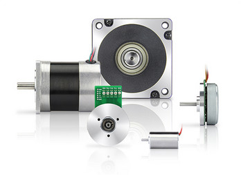
What is the significance of back EMF (electromotive force) in DC motor performance?
The significance of back EMF (electromotive force) in DC motor performance is crucial to understanding the behavior and operation of DC motors. Back EMF is an inherent characteristic of DC motors and plays a pivotal role in their efficiency, speed regulation, and overall performance. Here’s a detailed explanation of the significance of back EMF in DC motor performance:
When a DC motor operates, it generates a voltage known as back EMF or counter electromotive force. This voltage opposes the applied voltage and is caused by the rotation of the motor’s armature within the magnetic field. The back EMF is directly proportional to the rotational speed of the motor.
The significance of back EMF can be understood through the following aspects:
1. Speed Regulation:
Back EMF is crucial for regulating the speed of a DC motor. As the motor rotates faster, the back EMF increases, which reduces the effective voltage across the motor’s armature. Consequently, the armature current decreases, limiting the motor’s speed. This self-regulating characteristic helps maintain a relatively constant speed under varying load conditions. It allows the motor to deliver the required torque while preventing excessive speed that can potentially damage the motor or the driven equipment.
2. Efficiency:
Back EMF plays a significant role in the efficiency of a DC motor. When the motor is loaded and drawing current, the power supplied to the motor is the product of the armature current and the applied voltage. However, the electrical power converted into mechanical power is reduced by the power consumed by the back EMF. The back EMF represents the energy returned to the power supply as the motor generates its own voltage. By reducing the effective voltage across the motor, it helps minimize power losses due to electrical resistance and improves the overall efficiency of the motor.
3. Motor Protection:
The presence of back EMF also provides a level of protection to the motor. When a DC motor is operating and the load on the motor suddenly decreases, such as when the driven equipment is disconnected, the motor’s speed can increase rapidly. This increase in speed leads to a higher back EMF, which reduces the armature current and prevents excessive current flow. By limiting the current, the back EMF helps protect the motor from overloading and potential damage.
4. Voltage Regulation:
Back EMF affects the voltage regulation in a DC motor. When the motor is operating, the back EMF opposes the applied voltage. As the motor load increases, the voltage drop across the armature resistance and other internal losses also increase. The back EMF helps compensate for these voltage drops, ensuring that the motor receives an adequate voltage to maintain its performance and torque output.
5. Control and Dynamic Response:
Back EMF provides valuable information for motor control and dynamic response. By measuring the back EMF voltage, the rotational speed of the motor can be estimated, allowing for precise speed control and feedback. This information is crucial for applications that require accurate speed regulation, such as robotics or industrial automation.
In summary, the significance of back EMF in DC motor performance cannot be overstated. It influences speed regulation, efficiency, motor protection, voltage regulation, and control capabilities. By understanding and utilizing the inherent characteristics of back EMF, engineers can design and optimize DC motor systems for various applications, ensuring reliable and efficient operation.
Can DC motors be used in robotics, and if so, what are some notable applications?
Yes, DC (Direct Current) motors can be used in robotics, and they are widely employed in various robotic applications. DC motors offer several advantages that make them suitable for robotic systems, including their controllability, compact size, and versatility. Here’s a detailed explanation of how DC motors are used in robotics and some notable applications:
DC Motors in Robotics:
DC motors are commonly used in robotics due to their ability to provide precise speed control and torque output. They can be easily controlled by adjusting the voltage applied to the motor, allowing for accurate and responsive motion control in robotic systems. Additionally, DC motors can be designed in compact sizes, making them suitable for applications with limited space and weight constraints.
There are two main types of DC motors used in robotics:
- DC Brushed Motors: These motors have a commutator and carbon brushes that provide the electrical connection to the rotating armature. They are relatively simple in design and cost-effective. However, they may require maintenance due to brush wear.
- DC Brushless Motors: These motors use electronic commutation instead of brushes, resulting in improved reliability and reduced maintenance requirements. They are often more efficient and offer higher power density compared to brushed motors.
Notable Applications of DC Motors in Robotics:
DC motors find applications in various robotic systems across different industries. Here are some notable examples:
1. Robotic Manipulators: DC motors are commonly used in robotic arms and manipulators to control the movement of joints and end-effectors. They provide precise control over position, speed, and torque, allowing robots to perform tasks such as pick-and-place operations, assembly, and material handling in industrial automation, manufacturing, and logistics.
2. Mobile Robots: DC motors are extensively utilized in mobile robots, including autonomous vehicles, drones, and rovers. They power the wheels or propellers, enabling the robot to navigate and move in different environments. DC motors with high torque output are particularly useful for off-road or rugged terrain applications.
3. Humanoid Robots: DC motors play a critical role in humanoid robots, which aim to replicate human-like movements and capabilities. They are employed in various joints, including those of the head, arms, legs, and hands, allowing humanoid robots to perform complex movements and tasks such as walking, grasping objects, and facial expressions.
4. Robotic Exoskeletons: DC motors are used in robotic exoskeletons, which are wearable devices designed to enhance human strength and mobility. They provide the necessary actuation and power for assisting or augmenting human movements, such as walking, lifting heavy objects, and rehabilitation purposes.
5. Educational Robotics: DC motors are popular in educational robotics platforms and kits, including those used in schools, universities, and hobbyist projects. They provide a cost-effective and accessible way for students and enthusiasts to learn about robotics, programming, and control systems.
6. Precision Robotics: DC motors with high-precision control are employed in applications that require precise positioning and motion control, such as robotic surgery systems, laboratory automation, and 3D printing. The ability of DC motors to achieve accurate and repeatable movements makes them suitable for tasks that demand high levels of precision.
These are just a few examples of how DC motors are used in robotics. The flexibility, controllability, and compactness of DC motors make them a popular choice in a wide range of robotic applications, contributing to the advancement of automation, exploration, healthcare, and other industries.
editor by CX 2024-04-22
China high quality CHINAMFG 12V DC Starter Motors Fabricators Starter Motor 2stroke China 24V Bosch 0001231010 Starter Motor for Ive-Co with Great quality
Product Description
Starter Motor for Ive-Co 5 861049
Starting Motor
A starter is a device used to rotate an internal combustion engine in order to initiate the operation of the engine under its own power. The starter can be electric, pneumatic, or hydraulic. In the case of, for example, oversized engines or diesel engines in agricultural or excavation applications, the starter can also be another internal combustion engine. Internal combustion engines are feedback systems that, once started, rely on the inertia of each cycle to start the next cycle.
How A Starter Motor Works
It Can Be Explained By The Working Principle Of Its Main Component, The DC Motor. A DC Motor Is A Device That Converts Electrical Energy Into Mechanical Energy. It Is Based On The Principle That A Charged Conductor Is Subjected To Electromagnetic Force In A Magnetic Field. Because The Torque Generated By One Coil Is Too Small And The Speed Is Unstable, In Fact, There Are Many Coils Wound On The Armature Of The Motor, And The Number Of Commutation Pieces Also Increases Correspondingly With The Increase Of Coils. So As To Ensure Sufficient Torque And Stable Speed.
Notice
The Starting Time Of The Starter Motor Should Not Be Too Long Each Time, Generally Speaking, About 10 Seconds Is The Best. The Time Interval Between Starting The Motor Twice Is About 1 Minute, Preferably Greater Than 1 Minute. If It Cannot Be Started Three Times In A Row, The Engine, Battery, Circuit Lines, And Connection Points Should Be Checked At This Time.
For A Starter Motor Without An Overcurrent Protection Device, If It Cannot Be Started Three Times In A Row, The Starter Motor Must Be Stopped At This Time, Because The Starting Current Is Too Large, And The Starter Motor Will Overheat Due To Excessive Current During Long-Term Work; If You Continue To Forcibly Start The Motor, The Motor Will Most Likely Burn Out.
After Replacing The Starter Motor, You Should Pay Attention To The Contact Points Of The Positive And Negative Poles. It Is Best To Polish The Contact Points And Install Them Firmly, Otherwise, It Will Cause The Problem That The Engine Will Not Start When It Is Hot.
Product Parameters
| Product Name | Starter Motor |
| Keywords | Starting Motor |
| Brand | Neutral or Nitel |
| Voltage (V) | 24 |
| Kilowatt (Kw) | 4 |
| Teeth | 9 |
| Rotation | CW |
| Used on | for Iveco |
| Weight | Standard |
| Material | Metal |
| Certification | ISO/Ts16949 |
| Application | Iveco |
| Condition | 1 |
| Cargo 113183, 116347 | |
| CAS CST10661AS | |
| Delco 19084034 | |
| FIAT 75114529 | |
| Iveco 5 | |
| Motorherz STB3183WA | |
| WAI 19664N | |
| WPS 18030N, 19664N | |
| ZAUFER 300N11909Z |
FITS FOR
| FITS FOR | IVECO 109-14 5.5 [8060.04.689] 06.1983-12.1985 |
| IVECO 109-14 5.9 [8060.05.289] 11.1985-03.1991 | |
| IVECO 75 E 14 4.0 [8040.45.4000TCA] 01.1991- | |
| IVECO 79-13 5.5 [8060.04.060] 11.1979-12.1983 | |
| IVECO 79-14 5.5 [8060.04.660] 01.1983-11.1985 | |
| IVECO 79-14 5.9 [8060.05.280] 12.1985-03.1991 | |
| IVECO 95-14 5.5 [8060.04.669] 07.1983-10.1985 | |
| FIAT TRUCK 80 NC 1972-1980 8060.02/ | |
| FIAT TRUCK 90 F13 1978-1982 8060.04.055 |
Detailed Photos
About Us
Founded In 2571, ZheJiang CHINAMFG Electromechanical Co., Ltd. Is An Excellent Starter, Alternator, And Parts Supplier. Our High-Quality Motors Are Used In Heavy trucks, Mechanical, And Marine Engines. The Company Is Located In HangZhou ZheJiang , A National Historical And Cultural City Known As “The North Water City Of The Yangtze River”, With Convenient Transportation.
Since Its Establishment, The Company Has Formed A Perfect Product Structure, With More Than 10 Series Of Starter Motors And Alternators, And More Than 1000 Models. The Company Has Domestic Advanced Starter Motors, Alternator Production Lines, Complete Technical Equipment, And An Annual Production Capacity Of 500,000 Sets. The Main Products Are The Bosch Series, CHINAMFG Series, CHINAMFG Series, Prestolite Series, CHINAMFG Series, And So On. Our Products Are Suitable For All Kinds Of Engines And Trucks, Such As CHINAMFG Engines, CHINAMFG Engines, CHINAMFG Engines, CHINAMFG Power Engines, CHINAMFG Engines, CHINAMFG Engine, ZheJiang Diesel Engines, HangZhou Diesel Engines, Medium Heavy Automobiles, Freighter Trucks, International Truck, Etc.
The Products Have Been Exported To Russia, Spain, South Korea, Germany, The United Kingdom, The United States, Canada, Brazil, Argentina, India, Saudi Arabia, Pakistan, Kazakhstan, South Africa, Vietnam, Cambodia, And Other Countries.
FAQ
Q1:Are You A Manufacturer?
A: Yes, We Are A Starter Motor Manufacturer/Factory.
Q2: How Much Does The Sample Cost?
A: Please Contact Our Sales Staff And Tell Them The Model You Need, And They Will Check The Sample Cost For You (Some Are Free). And The Customer Pays The Delivery Cost.
Q3: How To Get A Quotation?
A: Please Suggest One Number Or Picture, Quantity, Etc., And Then Send Your Email To Us Or Talk To Our Staff Through The Trade Manager.
Q4: What Is The Minimum Order Quantity?
A: If We Have Stock, There Is No Minimum Order Quantity Limit. If Not, Please Contact Our Sales Staff, Different Items Are Different.
Q5: What About Your Service?
A: Timely. Be Careful. Before The Sale, We Will Use Our Software To Check The Correct OE Number To Avoid Errors. After Sending, We Will Track The Product For You Every Two Days Until You Get The Product.
Q6: Do You Test All Your Goods Before Delivery?
A: Yes, We Have 100% Test Before Delivery
Q7: How Do You Make Our Business Long-Term And Good Relationship?
A:1. We Keep Good Quality And Competitive Prices To Ensure Our Customers Benefit ;
2. We Respect Every Customer As Our Friend And We Sincerely Do Business And Make Friends With Them, No Matter Where They Come From.
/* January 22, 2571 19:08:37 */!function(){function s(e,r){var a,o={};try{e&&e.split(“,”).forEach(function(e,t){e&&(a=e.match(/(.*?):(.*)$/))&&1
| After-sales Service: | Free Replacement for Quality Problems Within 1 Yea |
|---|---|
| Warranty: | 1 Year |
| Car Make: | for Iveco |
| Engine Type: | 100% OEM Replacement |
| Control System: | Electromagnetic-Operated |
| DC Form: | Common Starter Motor |
| Samples: |
US$ 50/Piece
1 Piece(Min.Order) | |
|---|
| Customization: |
Available
|
|
|---|

What are the main components of a DC motor, and how do they contribute to its functionality?
A DC (Direct Current) motor consists of several key components that work together to enable its functionality. Each component plays a crucial role in the operation of the motor. Here’s a detailed explanation of the main components of a DC motor and their contributions:
1. Stator:
The stator is the stationary part of the motor. It typically consists of permanent magnets or electromagnets that produce a fixed magnetic field. The stator’s magnetic field interacts with the rotor’s magnetic field to generate the required torque for motor rotation. The stator provides the foundation for the motor’s magnetic field and contributes to its overall stability and efficiency.
2. Rotor:
The rotor is the rotating part of the motor and is connected to the motor’s output shaft. It contains coils or windings that carry the armature current. The rotor’s windings interact with the stator’s magnetic field, resulting in the generation of a mechanical force that causes the rotor to rotate. The rotor’s movement is responsible for converting electrical energy into mechanical motion, enabling the motor to perform its intended function.
3. Armature:
The armature is the core of the rotor that holds the armature windings. The armature windings are typically made of copper wire and are evenly spaced around the armature. When a current passes through the armature windings, a magnetic field is created around them. This magnetic field interacts with the stator’s magnetic field, resulting in the generation of a torque that drives the rotor’s rotation. The armature is a critical component that facilitates the conversion of electrical energy into mechanical energy.
4. Commutator:
The commutator is a cylindrical ring attached to the rotor shaft. It consists of multiple segments, usually made of copper, that are insulated from each other. The commutator plays a vital role in the DC motor’s operation by providing the necessary electrical connections to the armature windings. As the rotor spins, the brushes make physical contact with different commutator segments, effectively reversing the direction of the current in the armature windings at the appropriate timing. This reversal of current flow ensures that the torque generated in the armature windings is always in the same direction, allowing for continuous rotation of the rotor.
5. Brushes:
The brushes are stationary contacts that make physical contact with the commutator segments. They are typically made of carbon or graphite and provide electrical connections to the armature windings. The brushes supply the current to the armature windings through the commutator, allowing for the creation of the magnetic field necessary for motor operation. The brushes need to maintain proper contact with the commutator to ensure efficient electrical transmission and reliable motor performance.
6. Housing or Frame:
The housing or frame of the DC motor encloses and supports all the internal components. It provides structural integrity, protects the motor from external elements, and helps dissipate heat generated during operation. The housing or frame also serves as a mounting point for the motor, allowing it to be securely installed in various applications.
By understanding the main components of a DC motor and their contributions, one can gain insights into how each part works together harmoniously to achieve the desired motor functionality.
Can DC motors be used in renewable energy systems, such as wind turbines or solar tracking systems?
Yes, DC (Direct Current) motors can be effectively used in various renewable energy systems, including wind turbines and solar tracking systems. The unique characteristics and advantages of DC motors make them well-suited for these applications. Here’s a detailed explanation of how DC motors can be utilized in renewable energy systems:
1. Wind Turbines:
DC motors can be employed in wind turbines to convert the mechanical energy of the wind into electrical energy. There are two common configurations:
a. Direct Drive Wind Turbines:
In direct drive wind turbines, the rotor of the turbine is directly connected to a DC generator. The rotor’s rotational motion is transmitted directly to the generator, which produces DC electrical power. DC motors can be used as DC generators in this configuration. The advantage of using DC motors/generators is their simplicity, reliability, and ability to operate efficiently at variable speeds, which is beneficial in varying wind conditions.
b. Hybrid Wind Turbines:
Hybrid wind turbines combine both aerodynamic and electrical conversion systems. In this configuration, DC motors can be utilized for the pitch control mechanism and yaw control system. The pitch control mechanism adjusts the angle of the turbine blades to optimize performance, while the yaw control system enables the turbine to align itself with the wind direction. DC motors provide precise control and responsiveness required for these functions.
2. Solar Tracking Systems:
DC motors are commonly employed in solar tracking systems to maximize the efficiency of solar panels by optimizing their orientation towards the sun. There are two main types of solar tracking systems:
a. Single-Axis Solar Tracking Systems:
Single-axis solar tracking systems adjust the inclination of solar panels along a single axis (typically the east-west axis) to track the movement of the sun throughout the day. DC motors can be used to drive the rotation mechanism that adjusts the panel’s tilt angle. By continuously adjusting the panel’s position to face the sun directly, the solar energy harvested can be significantly increased, resulting in higher energy output compared to fixed solar panel installations.
b. Dual-Axis Solar Tracking Systems:
Dual-axis solar tracking systems adjust the inclination of solar panels along both the east-west and north-south axes to track the sun’s movement throughout the day and throughout the year. DC motors are utilized in the rotation mechanisms for both axes. This type of solar tracking system provides the highest possible energy yield by keeping the solar panels perpendicular to the sun’s rays at all times, maximizing the exposure to sunlight.
DC motors are preferred in renewable energy systems due to their advantages, including:
- Efficiency at Variable Speeds: DC motors can operate efficiently at varying speeds, making them suitable for applications with fluctuating wind speeds or changing solar angles.
- Control and Precision: DC motors offer precise control and responsiveness, allowing for accurate tracking and adjustment in wind turbines and solar tracking systems.
- Reliability: DC motors are known for their reliability, with fewer moving parts compared to other motor types, reducing the risk of failure in remote or harsh environments.
- Compatibility with Energy Storage Systems: DC motors can easily be integrated with energy storage systems, such as batteries or supercapacitors, to store excess electrical energy generated by wind turbines or solar panels.
In conclusion, DC motors can be effectively utilized in renewable energy systems such as wind turbines and solar tracking systems. Their efficiency, control capabilities, reliability, and compatibility with energy storage systems make them a suitable choice for these applications, contributing to the advancement of sustainable energy generation.
Are there innovations or emerging technologies in the field of DC motor design?
Yes, there have been several innovations and emerging technologies in the field of DC (Direct Current) motor design. These advancements aim to improve the performance, efficiency, reliability, and overall capabilities of DC motors. Here’s a detailed explanation of some notable innovations and emerging technologies in DC motor design:
1. Brushless DC Motors:
One significant advancement in DC motor design is the development and widespread adoption of brushless DC motors (BLDC motors). Unlike traditional DC motors that use brushes for commutation, BLDC motors employ electronic commutation through the use of permanent magnets and motor controller circuits. This eliminates the need for brushes, reducing maintenance requirements and improving overall motor efficiency and lifespan. BLDC motors offer higher torque density, smoother operation, better speed control, and improved energy efficiency compared to conventional brushed DC motors.
2. High-Efficiency Materials:
The use of high-efficiency materials in DC motor design has been an area of focus for improving motor performance. Advanced magnetic materials, such as neodymium magnets, have allowed for stronger and more compact motor designs. These materials increase the motor’s power density, enabling higher torque output and improved efficiency. Additionally, advancements in materials used for motor windings and core laminations have reduced electrical losses and improved overall motor efficiency.
3. Power Electronics and Motor Controllers:
Advancements in power electronics and motor control technologies have greatly influenced DC motor design. The development of sophisticated motor controllers and efficient power electronic devices enables precise control of motor speed, torque, and direction. These technologies have resulted in more efficient and reliable motor operation, reduced energy consumption, and enhanced motor performance in various applications.
4. Integrated Motor Systems:
Integrated motor systems combine the motor, motor controller, and associated electronics into a single unit. These integrated systems offer compact designs, simplified installation, and improved overall performance. By integrating the motor and controller, issues related to compatibility and communication between separate components are minimized. Integrated motor systems are commonly used in applications such as robotics, electric vehicles, and industrial automation.
5. IoT and Connectivity:
The integration of DC motors with Internet of Things (IoT) technologies and connectivity has opened up new possibilities for monitoring, control, and optimization of motor performance. By incorporating sensors, actuators, and connectivity features, DC motors can be remotely monitored, diagnosed, and controlled. This enables predictive maintenance, energy optimization, and real-time performance adjustments, leading to improved efficiency and reliability in various applications.
6. Advanced Motor Control Algorithms:
Advanced motor control algorithms, such as sensorless control and field-oriented control (FOC), have contributed to improved performance and efficiency of DC motors. Sensorless control techniques eliminate the need for additional sensors by leveraging motor current and voltage measurements to estimate rotor position. FOC algorithms optimize motor control by aligning the magnetic field with the rotor position, resulting in improved torque and efficiency, especially at low speeds.
These innovations and emerging technologies in DC motor design have revolutionized the capabilities and performance of DC motors. Brushless DC motors, high-efficiency materials, advanced motor control techniques, integrated motor systems, IoT connectivity, and advanced control algorithms have collectively contributed to more efficient, reliable, and versatile DC motor solutions across various industries and applications.
editor by CX 2024-04-19