Product Description
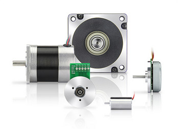
High-speed doors servo control system
DC High Speed Curtain Roller Shutter Tubular Central Motor
Features
- Intelligent human-computer interaction interface, LCD display, built-in Chinese and English
- Convenient wiring and simple operation
- Built-in brake released battery,the brake can be quickly released with 1 button when power off
- Low noise, stable operation and high efficiency
- High-quality IPM intelligent module, with strong performance and full protection function
- Record running time and number of times, lock and maintenance time can be set
- Real-time monitor external signals and system alarm functions
- Input and output ports can be edited to set multiple functions
- The product is suitable for all kinds of PVC high-speed doors,PVC high-speed Fold-up doors and spiral doors.
Technical Parameter
| Model | FD300 | ||
| Rated Power | 0.75kw | 1.5kw | 2.5kw |
| Brake Release Battery | None | Built-in | |
| Input Voltage | 1P,AC220V±15%/50~60Hz | ||
| Limit Control | Ab olute Encoder,Mechanical Limit | ||
| Overload Capacity | 300% Rated 10s,150% Rated 60s | ||
| Output Power | DC24V/1A | ||
| Temperature | -20ºC ~ 50ºC | ||
| Dimension | 360×23 ×100mm | ||
| Weight | 5.2kg | ||
Brief description of common parameters
Low power silent high-speed servo motor
Features
- High speed, rated speed 3000 rpm, maximum 5000 rpm
- Aviation aluminum shell, exquisite appearance and good heat dissipati n
- Built-in absolute encoder, easy to install
- Constant high torque output, up to 300 overload capacity
- Applicable to a wide range of environments, -40ºC~70ºC
- No mechanical brake, quiet and stable
- Advanced short-circuit electromagnetic brake, self-locking after power off
| Size Type |
A | B | C | D | E | F | Weight (kg) | |
| 0.75kw | RV050 | 120 | 145 | 90 | 300 | 150 | 30 | 7.7 |
| 0.75kw | RV063 | 145 | 175 | 110 | 325 | 150 | 30 | 9.9 |
| 1.1kw | RV050 | 120 | 145 | 90 | 330 | 180 | 30 | 8.6 |
| 1.1kw | RV063 | 145 | 175 | 110 | 355 | 180 | 30 | 10.8 |
| Model | FDHDM22150 | |
| Rated Power | 0.75kw | 1.1kw |
| Insulation Gr de | F | |
| IP | IP65 | |
| Encoder | bsolute Encoder Built-in | |
| Brake | none mechanical brake | |
| Output Rotating Speed | 3000RPM | |
| Output Torque | 2.39N.m | 3.5N.m |
| Reduction Gear | 050(063 Optional)Standard 1:30 | |
High-power high-speed servo motor
Features
- High speed, rated speed 2500 rpm, maximum 4000 rpm
- Aviation aluminum shell, exquisite appearance and good heat dissipation
- Built-in absolute encoder, easy to install
- Constant high torque output, up to 300 overload capacity
- Applicable to a wide range of environments, -40ºC~70ºC
- DC 24V mechanical brake, easily released by 1 key of the controller when power off
| Size Type | A | B | C | D | E | F | Weight (kg) | |
| 1.5kw | RV063 | 144 | 200 | 103 | 403 | 236 | 30 | 16.2 |
| 2.0kw | RV063 | 144 | 200 | 103 | 410 | 249 | 30 | 17.5 |
| 2.5kw | RV063 | 144 | 200 | 103 | 452 | 252 | 30 | 18.5 |
| Model | FDHDM22220 | ||
| Rated Power | 1.5kw | 2kw | 2.5kw |
| Insulation Gr de | F | ||
| IP | IP65 | ||
| Encoder | Absolute Encoder B ilt-in | ||
| Brake | DC24 Brake | ||
| Output Rotating Speed | 2500RPM | ||
| Output Torque | 6N.m | 8N.m | 10N.m |
| Reduction Gear | 063(075 Optional)Standard 1:25 | ||
| Reduction Gear | D | b | M | N | KE | C | E | L |
| RV50 | 25 | 8 | 85 | 70 | M8×10 | 120 | 144 | 85 |
| RV63 | 25 | 8 | 95 | 80 | M8×14 | 144 | 174 | 103 |
| RV75 | 28 | 8 | 115 | 95 | M8×14 | 174 | 205 | 113 |
| RV90 | 28 | 10 | 130 | 110 | M10×10 | 208 | 238 | 130 |
High-speed tubular servo motor
90/130 Planetary gear servo motor
/* January 22, 2571 19:08:37 */!function(){function s(e,r){var a,o={};try{e&&e.split(“,”).forEach(function(e,t){e&&(a=e.match(/(.*?):(.*)$/))&&1
| Structure: | Straight Arm |
|---|---|
| Driving Type: | Electromechanical |
| Electric Current Type: | AC |
| Brand: | Everbright |
| Output Power: | DC24V / 1A |
| Input Voltage: | 1p,AC220V±15%/50~60Hz |
| Samples: |
US$ 300/Piece
1 Piece(Min.Order) | |
|---|
| Customization: |
Available
|
|
|---|

How does the speed control of a DC motor work, and what methods are commonly employed?
The speed control of a DC (Direct Current) motor is essential for achieving precise control over its rotational speed. Various methods can be employed to regulate the speed of a DC motor, depending on the specific application requirements. Here’s a detailed explanation of how speed control of a DC motor works and the commonly employed methods:
1. Voltage Control:
One of the simplest methods to control the speed of a DC motor is by varying the applied voltage. By adjusting the voltage supplied to the motor, the electromotive force (EMF) induced in the armature windings can be controlled. According to the principle of electromagnetic induction, the speed of the motor is inversely proportional to the applied voltage. Therefore, reducing the voltage decreases the speed, while increasing the voltage increases the speed. This method is commonly used in applications where a simple and inexpensive speed control mechanism is required.
2. Armature Resistance Control:
Another method to control the speed of a DC motor is by varying the armature resistance. By inserting an external resistance in series with the armature windings, the total resistance in the circuit increases. This increase in resistance reduces the armature current, thereby reducing the motor’s speed. Conversely, reducing the resistance increases the armature current and the motor’s speed. However, this method results in significant power loss and reduced motor efficiency due to the dissipation of excess energy as heat in the external resistance.
3. Field Flux Control:
Speed control can also be achieved by controlling the magnetic field strength of the motor’s stator. By altering the field flux, the interaction between the armature current and the magnetic field changes, affecting the motor’s speed. This method can be accomplished by adjusting the field current through the field windings using a field rheostat or by employing a separate power supply for the field windings. By increasing or decreasing the field flux, the speed of the motor can be adjusted accordingly. This method offers good speed regulation and efficiency but requires additional control circuitry.
4. Pulse Width Modulation (PWM):
Pulse Width Modulation is a widely used technique for speed control in DC motors. It involves rapidly switching the applied voltage on and off at a high frequency. The duty cycle, which represents the percentage of time the voltage is on, is varied to control the effective voltage applied to the motor. By adjusting the duty cycle, the average voltage across the motor is modified, thereby controlling its speed. PWM provides precise speed control, high efficiency, and low power dissipation. It is commonly employed in applications such as robotics, industrial automation, and electric vehicles.
5. Closed-Loop Control:
In closed-loop control systems, feedback from the motor’s speed or other relevant parameters is used to regulate the speed. Sensors such as encoders or tachometers measure the motor’s actual speed, which is compared to the desired speed. The difference, known as the error signal, is fed into a control algorithm that adjusts the motor’s input voltage or other control parameters to minimize the error and maintain the desired speed. Closed-loop control provides excellent speed regulation and accuracy, making it suitable for applications that require precise speed control, such as robotics and CNC machines.
These methods of speed control provide flexibility and adaptability to various applications, allowing DC motors to be effectively utilized in a wide range of industries and systems.
What is the significance of back EMF (electromotive force) in DC motor performance?
The significance of back EMF (electromotive force) in DC motor performance is crucial to understanding the behavior and operation of DC motors. Back EMF is an inherent characteristic of DC motors and plays a pivotal role in their efficiency, speed regulation, and overall performance. Here’s a detailed explanation of the significance of back EMF in DC motor performance:
When a DC motor operates, it generates a voltage known as back EMF or counter electromotive force. This voltage opposes the applied voltage and is caused by the rotation of the motor’s armature within the magnetic field. The back EMF is directly proportional to the rotational speed of the motor.
The significance of back EMF can be understood through the following aspects:
1. Speed Regulation:
Back EMF is crucial for regulating the speed of a DC motor. As the motor rotates faster, the back EMF increases, which reduces the effective voltage across the motor’s armature. Consequently, the armature current decreases, limiting the motor’s speed. This self-regulating characteristic helps maintain a relatively constant speed under varying load conditions. It allows the motor to deliver the required torque while preventing excessive speed that can potentially damage the motor or the driven equipment.
2. Efficiency:
Back EMF plays a significant role in the efficiency of a DC motor. When the motor is loaded and drawing current, the power supplied to the motor is the product of the armature current and the applied voltage. However, the electrical power converted into mechanical power is reduced by the power consumed by the back EMF. The back EMF represents the energy returned to the power supply as the motor generates its own voltage. By reducing the effective voltage across the motor, it helps minimize power losses due to electrical resistance and improves the overall efficiency of the motor.
3. Motor Protection:
The presence of back EMF also provides a level of protection to the motor. When a DC motor is operating and the load on the motor suddenly decreases, such as when the driven equipment is disconnected, the motor’s speed can increase rapidly. This increase in speed leads to a higher back EMF, which reduces the armature current and prevents excessive current flow. By limiting the current, the back EMF helps protect the motor from overloading and potential damage.
4. Voltage Regulation:
Back EMF affects the voltage regulation in a DC motor. When the motor is operating, the back EMF opposes the applied voltage. As the motor load increases, the voltage drop across the armature resistance and other internal losses also increase. The back EMF helps compensate for these voltage drops, ensuring that the motor receives an adequate voltage to maintain its performance and torque output.
5. Control and Dynamic Response:
Back EMF provides valuable information for motor control and dynamic response. By measuring the back EMF voltage, the rotational speed of the motor can be estimated, allowing for precise speed control and feedback. This information is crucial for applications that require accurate speed regulation, such as robotics or industrial automation.
In summary, the significance of back EMF in DC motor performance cannot be overstated. It influences speed regulation, efficiency, motor protection, voltage regulation, and control capabilities. By understanding and utilizing the inherent characteristics of back EMF, engineers can design and optimize DC motor systems for various applications, ensuring reliable and efficient operation.
Are there innovations or emerging technologies in the field of DC motor design?
Yes, there have been several innovations and emerging technologies in the field of DC (Direct Current) motor design. These advancements aim to improve the performance, efficiency, reliability, and overall capabilities of DC motors. Here’s a detailed explanation of some notable innovations and emerging technologies in DC motor design:
1. Brushless DC Motors:
One significant advancement in DC motor design is the development and widespread adoption of brushless DC motors (BLDC motors). Unlike traditional DC motors that use brushes for commutation, BLDC motors employ electronic commutation through the use of permanent magnets and motor controller circuits. This eliminates the need for brushes, reducing maintenance requirements and improving overall motor efficiency and lifespan. BLDC motors offer higher torque density, smoother operation, better speed control, and improved energy efficiency compared to conventional brushed DC motors.
2. High-Efficiency Materials:
The use of high-efficiency materials in DC motor design has been an area of focus for improving motor performance. Advanced magnetic materials, such as neodymium magnets, have allowed for stronger and more compact motor designs. These materials increase the motor’s power density, enabling higher torque output and improved efficiency. Additionally, advancements in materials used for motor windings and core laminations have reduced electrical losses and improved overall motor efficiency.
3. Power Electronics and Motor Controllers:
Advancements in power electronics and motor control technologies have greatly influenced DC motor design. The development of sophisticated motor controllers and efficient power electronic devices enables precise control of motor speed, torque, and direction. These technologies have resulted in more efficient and reliable motor operation, reduced energy consumption, and enhanced motor performance in various applications.
4. Integrated Motor Systems:
Integrated motor systems combine the motor, motor controller, and associated electronics into a single unit. These integrated systems offer compact designs, simplified installation, and improved overall performance. By integrating the motor and controller, issues related to compatibility and communication between separate components are minimized. Integrated motor systems are commonly used in applications such as robotics, electric vehicles, and industrial automation.
5. IoT and Connectivity:
The integration of DC motors with Internet of Things (IoT) technologies and connectivity has opened up new possibilities for monitoring, control, and optimization of motor performance. By incorporating sensors, actuators, and connectivity features, DC motors can be remotely monitored, diagnosed, and controlled. This enables predictive maintenance, energy optimization, and real-time performance adjustments, leading to improved efficiency and reliability in various applications.
6. Advanced Motor Control Algorithms:
Advanced motor control algorithms, such as sensorless control and field-oriented control (FOC), have contributed to improved performance and efficiency of DC motors. Sensorless control techniques eliminate the need for additional sensors by leveraging motor current and voltage measurements to estimate rotor position. FOC algorithms optimize motor control by aligning the magnetic field with the rotor position, resulting in improved torque and efficiency, especially at low speeds.
These innovations and emerging technologies in DC motor design have revolutionized the capabilities and performance of DC motors. Brushless DC motors, high-efficiency materials, advanced motor control techniques, integrated motor systems, IoT connectivity, and advanced control algorithms have collectively contributed to more efficient, reliable, and versatile DC motor solutions across various industries and applications.


editor by CX 2024-05-03
China Best Sales 12V 24V High Speed 28mm Diameter DC Planetary Gear Motor with Great quality
Product Description
12v 24v High-Speed 28mm Diameter DC Planetary Gear Motor
Model A
Model B
Model C
Note: We only show several motor models, if these models are not what you want, please freely tell us about your requirement. We will provide you with a suitable motor solution and price soon.
Our Workshop
Other Motors
Certificates
FAQ
1 Q: What’s your MOQ?
A: 1 unit is acceptable.
2 Q: What about your warranty?
A: One year.
3 Q: Do you provide OEM service with customer-logo?
A: Yes, we could do OEM orders, but we mainly focus on our own brand.
4 Q: How about your payment terms?
A: TT, western union and Paypal. 100% payment in advance for orders less $5,000. 30% deposit and balance before delivery for orders over $5,000.
5 Q: How about your packing?
A: Carton, Plywood case and foam inside. If you need more, we can pack all the goods with pallet.
6 Q: What information should be given, if I buy from you?
A: Rated power, gearbox ratio, input speed, mounting position. More details, better!
7 Q: How do you deliver?
A: We will compare and choose the most suitable ways of delivery by sea, air or express courier.
We hope you will enjoy cooperating with us. /* January 22, 2571 19:08:37 */!function(){function s(e,r){var a,o={};try{e&&e.split(“,”).forEach(function(e,t){e&&(a=e.match(/(.*?):(.*)$/))&&1
| Application: | Universal, Industrial, Household Appliances, Power Tools |
|---|---|
| Operating Speed: | High Speed |
| Function: | Driving |
| Casing Protection: | Protection Type |
| Structure and Working Principle: | Brush |
| Certification: | Ce |
| Samples: |
US$ 20/Piece
1 Piece(Min.Order) | |
|---|
| Customization: |
Available
|
|
|---|

Can gear motors be used in robotics, and if so, what are some notable applications?
Yes, gear motors are widely used in robotics due to their ability to provide torque, precise control, and compact size. They play a crucial role in various robotic applications, enabling the movement, manipulation, and control of robotic systems. Here are some notable applications of gear motors in robotics:
1. Robotic Arm Manipulation:
Gear motors are commonly used in robotic arms to provide precise and controlled movement. They enable the articulation of the arm’s joints, allowing the robot to reach different positions and orientations. Gear motors with high torque capabilities are essential for lifting, rotating, and manipulating objects with varying weights and sizes.
2. Mobile Robots:
Gear motors are employed in mobile robots, including wheeled robots and legged robots, to drive their locomotion. They provide the necessary torque and control for the robot to move, turn, and navigate in different environments. Gear motors with appropriate gear ratios ensure the robot’s mobility, stability, and maneuverability.
3. Robotic Grippers and End Effectors:
Gear motors are used in robotic grippers and end effectors to control the opening, closing, and gripping force. By integrating gear motors into the gripper mechanism, robots can grasp and manipulate objects of various shapes, sizes, and weights. The gear motors enable precise control over the gripping action, allowing the robot to handle delicate or fragile objects with care.
4. Autonomous Drones and UAVs:
Gear motors are utilized in the propulsion systems of autonomous drones and unmanned aerial vehicles (UAVs). They drive the propellers or rotors, providing the necessary thrust and control for the drone’s flight. Gear motors with high power-to-weight ratios, efficient energy conversion, and precise speed control are crucial for achieving stable and maneuverable flight in drones.
5. Humanoid Robots:
Gear motors are integral to the movement and functionality of humanoid robots. They are used in robotic joints, such as hips, knees, and shoulders, to enable human-like movements. Gear motors with appropriate torque and speed capabilities allow humanoid robots to walk, run, climb stairs, and perform complex motions resembling human actions.
6. Robotic Exoskeletons:
Gear motors play a vital role in robotic exoskeletons, which are wearable robotic devices designed to augment human strength and assist in physical tasks. Gear motors are used in the exoskeleton’s joints and actuators, providing the necessary torque and control to enhance human abilities. They enable users to perform tasks with reduced effort, assist in rehabilitation, or provide support in physically demanding environments.
These are just a few notable applications of gear motors in robotics. Their versatility, torque capabilities, precise control, and compact size make them indispensable components in various robotic systems. Gear motors enable robots to perform complex tasks, move with agility, interact with the environment, and assist humans in a wide range of applications, from industrial automation to healthcare and exploration.

What are some common challenges or issues associated with gear motors, and how can they be addressed?
Gear motors, like any mechanical system, can face certain challenges or issues that may affect their performance, reliability, or longevity. However, many of these challenges can be addressed through proper design, maintenance, and operational practices. Here are some common challenges associated with gear motors and potential solutions:
1. Gear Wear and Failure:
Over time, gears in a gear motor can experience wear, resulting in decreased performance or even failure. The following measures can address this challenge:
- Proper Lubrication: Regular lubrication with the appropriate lubricant can minimize friction and wear between gear teeth. It is essential to follow manufacturer recommendations for lubrication intervals and use high-quality lubricants suitable for the specific gear motor.
- Maintenance and Inspection: Routine maintenance and periodic inspections can help identify early signs of gear wear or damage. Timely replacement of worn gears or components can prevent further damage and ensure the gear motor’s optimal performance.
- Material Selection: Choosing gears made from durable and wear-resistant materials, such as hardened steel or specialized alloys, can increase their lifespan and resistance to wear.
2. Backlash and Inaccuracy:
Backlash, as discussed earlier, can introduce inaccuracies in gear motor systems. The following approaches can help address this issue:
- Anti-Backlash Gears: Using anti-backlash gears, which are designed to minimize or eliminate backlash, can significantly reduce inaccuracies caused by gear play.
- Tight Manufacturing Tolerances: Ensuring precise manufacturing tolerances during gear production helps minimize backlash and improve overall accuracy.
- Backlash Compensation: Implementing control algorithms or mechanisms to compensate for backlash can help mitigate its effects and improve the accuracy of the gear motor.
3. Noise and Vibrations:
Gear motors can generate noise and vibrations during operation, which may be undesirable in certain applications. The following strategies can help mitigate this challenge:
- Noise Dampening: Incorporating noise-dampening features, such as vibration-absorbing materials or isolation mounts, can reduce noise and vibrations transmitted from the gear motor to the surrounding environment.
- Quality Gears and Bearings: Using high-quality gears and bearings can minimize vibrations and noise generation. Precision-machined gears and well-maintained bearings help ensure smooth operation and reduce unwanted noise.
- Proper Alignment: Ensuring accurate alignment of gears, shafts, and other components reduces the likelihood of noise and vibrations caused by misalignment. Regular inspections and adjustments can help maintain optimal alignment.
4. Overheating and Thermal Management:
Heat buildup can be a challenge in gear motors, especially during prolonged or heavy-duty operation. Effective thermal management techniques can address this issue:
- Adequate Ventilation: Providing proper ventilation and airflow around the gear motor helps dissipate heat. This can involve designing cooling fins, incorporating fans or blowers, or ensuring sufficient clearance for air circulation.
- Heat Dissipation Materials: Using heat-dissipating materials, such as aluminum or copper, in motor housings or heat sinks can improve heat dissipation and prevent overheating.
- Monitoring and Control: Implementing temperature sensors and thermal protection mechanisms allows for real-time monitoring of the gear motor’s temperature. If the temperature exceeds safe limits, the motor can be automatically shut down or adjusted to prevent damage.
5. Load Variations and Shock Loads:
Unexpected load variations or shock loads can impact the performance and durability of gear motors. The following measures can help address this challenge:
- Proper Sizing and Selection: Choosing gear motors with appropriate torque and load capacity ratings for the intended application helps ensure they can handle expected load variations and occasional shock loads without exceeding their limits.
- Shock Absorption: Incorporating shock-absorbing mechanisms, such as dampers or resilient couplings, can help mitigate the effects of sudden load changes or impacts on the gear motor.
- Load Monitoring: Implementing load monitoring systems or sensors allows for real-time monitoring of load variations. This information can be used to adjust operation or trigger protective measures when necessary.
By addressing these common challenges associated with gear motors through appropriate design considerations, regular maintenance, and operational practices, it is possible to enhance their performance, reliability, and longevity.

Are there specific considerations for selecting the right gear motor for a particular application?
When selecting a gear motor for a specific application, several considerations need to be taken into account. The choice of the right gear motor is crucial to ensure optimal performance, efficiency, and reliability. Here’s a detailed explanation of the specific considerations for selecting the right gear motor for a particular application:
1. Torque Requirement:
The torque requirement of the application is a critical factor in gear motor selection. Determine the maximum torque that the gear motor needs to deliver to perform the required tasks. Consider both the starting torque (the torque required to initiate motion) and the operating torque (the torque required to sustain motion). Select a gear motor that can provide adequate torque to handle the load requirements of the application. It’s important to account for any potential torque spikes or variations during operation.
2. Speed Requirement:
Consider the desired speed range or specific speed requirements of the application. Determine the rotational speed (in RPM) that the gear motor needs to achieve to meet the application’s performance criteria. Select a gear motor with a suitable gear ratio that can achieve the desired speed at the output shaft. Ensure that the gear motor can maintain the required speed consistently and accurately throughout the operation.
3. Duty Cycle:
Evaluate the duty cycle of the application, which refers to the ratio of operating time to rest or idle time. Consider whether the application requires continuous operation or intermittent operation. Determine the duty cycle’s impact on the gear motor, including factors such as heat generation, cooling requirements, and potential wear and tear. Select a gear motor that is designed to handle the expected duty cycle and ensure long-term reliability and durability.
4. Environmental Factors:
Take into account the environmental conditions in which the gear motor will operate. Consider factors such as temperature extremes, humidity, dust, vibrations, and exposure to chemicals or corrosive substances. Choose a gear motor that is specifically designed to withstand and perform optimally under the anticipated environmental conditions. This may involve selecting gear motors with appropriate sealing, protective coatings, or materials that can resist corrosion and withstand harsh environments.
5. Efficiency and Power Requirements:
Consider the desired efficiency and power consumption of the gear motor. Evaluate the power supply available for the application and select a gear motor that operates within the specified voltage and current ranges. Assess the gear motor’s efficiency to ensure that it maximizes power transmission and minimizes wasted energy. Choosing an efficient gear motor can contribute to cost savings and reduced environmental impact.
6. Physical Constraints:
Assess the physical constraints of the application, including space limitations, mounting options, and integration requirements. Consider the size, dimensions, and weight of the gear motor to ensure it can be accommodated within the available space. Evaluate the mounting options and compatibility with the application’s mechanical structure. Additionally, consider any specific integration requirements, such as shaft dimensions, connectors, or interfaces that need to align with the application’s design.
7. Noise and Vibration:
Depending on the application, noise and vibration levels may be critical factors. Evaluate the acceptable noise and vibration levels for the application’s environment and operation. Choose a gear motor that is designed to minimize noise and vibration, such as those with helical gears or precision engineering. This is particularly important in applications that require quiet operation or where excessive noise and vibration may cause issues or discomfort.
By considering these specific factors when selecting a gear motor for a particular application, you can ensure that the chosen gear motor meets the performance requirements, operates efficiently, and provides reliable and consistent power transmission. It’s important to consult with gear motor manufacturers or experts to determine the most suitable gear motor based on the specific application’s needs.
editor by CX 2024-04-26
China Standard Made in China 42bl60s06-230 NEMA17 Small Size High Speed 3000rpm 60W 24V Brushless BLDC DC Motor for Polish vacuum pump distributors
Product Description
Product Description
Made in china 42BL60S06-230 Nema17 Small size high speed 3000rpm 60W 24V brushless bldc dc motor for polish
Note: the motor with magnetic ,so magnetic inspection fee will be incurred during transportation. Please contact shop assistant to supplement it.large quantities can dispense with it
| KeyWords | Brushless DC Motor |
| Model | 42BL60S06-230TR9 |
| Phase | 3 |
| Rotor poles | 8 |
| Rated Voltage | 24V |
| No load speed | 5500±10% |
| No load current (Max) | 0.4A |
| Rated Speed | 3000±10% |
| Rated Torque | 0.19NM |
| Rated power | 60W |
| Rated Current (Max) | 4.2A |
| Insulaiting strength | 500VAC |
| IP class | IP40 |
| Quality guarantee | 1 year |
| Mass | 0.45Kg |
Click have a discount
Click have a discount
BLDC products
Click the picture model number
jump the product page
BLDC PRODUCTS 1
Our Services
Company Information
Our Certificate
/* January 22, 2571 19:08:37 */!function(){function s(e,r){var a,o={};try{e&&e.split(“,”).forEach(function(e,t){e&&(a=e.match(/(.*?):(.*)$/))&&1
| Application: | Industrial |
|---|---|
| Operating Speed: | Constant Speed |
| Excitation Mode: | Compound |
| Customization: |
Available
|
|
|---|
.shipping-cost-tm .tm-status-off{background: none;padding:0;color: #1470cc}
|
Shipping Cost:
Estimated freight per unit. |
about shipping cost and estimated delivery time. |
|---|
| Payment Method: |
|
|---|---|
|
Initial Payment Full Payment |
| Currency: | US$ |
|---|
| Return&refunds: | You can apply for a refund up to 30 days after receipt of the products. |
|---|

Can you explain the basic working principle behind a DC motor?
A DC (Direct Current) motor operates based on the fundamental principle of electromagnetic induction. It converts electrical energy into mechanical motion by utilizing the interaction between magnetic fields and current-carrying conductors. Here’s a detailed explanation of the basic working principle behind a DC motor:
1. Construction:
A DC motor consists of several key components:
- Stator: The stator is the stationary part of the motor and typically consists of permanent magnets or electromagnets that produce a fixed magnetic field.
- Rotor: The rotor is the moving part of the motor and is connected to the shaft. It contains coils or windings that carry the armature current.
- Armature: The armature is the core of the rotor that holds the armature windings. The windings are usually made of copper wire and are evenly spaced around the armature.
- Commutator: The commutator is a cylindrical ring attached to the rotor shaft. It consists of multiple segments, usually made of copper, that are insulated from each other.
- Brushes: The brushes are stationary contacts that make physical contact with the commutator segments. They are typically made of carbon or graphite and provide electrical connections to the armature windings.
2. Electromagnetic Induction:
When a current-carrying conductor is placed in a magnetic field, it experiences a force due to the interaction between the magnetic field and the current. This phenomenon is described by the right-hand rule, where the direction of the force is perpendicular to both the current direction and the magnetic field direction.
3. Motor Operation:
When a DC motor is powered, a DC voltage is applied to the armature windings through the brushes and commutator. The current flowing through the armature windings creates a magnetic field around the windings. This magnetic field interacts with the fixed magnetic field produced by the stator, resulting in a force that causes the rotor to rotate.
4. Commutation:
The commutation process is crucial for the continuous rotation of the rotor in a DC motor. As the rotor spins, the brushes make contact with different commutator segments, effectively reversing the direction of the current in the armature windings at the appropriate timing. This reversal of current flow ensures that the torque generated in the armature windings is always in the same direction, allowing for continuous rotation of the rotor.
5. Speed Control:
The speed of a DC motor can be controlled by varying the applied voltage. Reducing the voltage results in a decrease in the magnetic field strength, which in turn decreases the force acting on the armature windings. This reduction in force leads to a decrease in the motor’s speed. Conversely, increasing the voltage increases the speed of the motor. Precise speed control can be achieved by using electronic circuits to regulate the voltage supplied to the motor.
6. Advantages and Applications:
DC motors offer several advantages, including:
- High starting torque, making them suitable for applications requiring high initial force.
- Excellent speed control capabilities, allowing for precise and adjustable speed regulation.
- Relatively simple construction and ease of maintenance.
- Wide range of sizes and power ratings, making them adaptable to various applications.
DC motors find extensive use in numerous applications, such as robotics, industrial automation, electric vehicles, appliances, and more.
By understanding the basic working principle behind a DC motor, one can appreciate its functionality and explore its applications in different fields.

How is the efficiency of a DC motor determined, and what factors can affect it?
In a DC (Direct Current) motor, efficiency refers to the ratio of the motor’s output power (mechanical power) to its input power (electrical power). It is a measure of how effectively the motor converts electrical energy into mechanical work. The efficiency of a DC motor can be determined by considering several factors that affect its performance. Here’s a detailed explanation of how the efficiency of a DC motor is determined and the factors that can influence it:
The efficiency of a DC motor is calculated using the following formula:
Efficiency = (Output Power / Input Power) × 100%
1. Output Power: The output power of a DC motor is the mechanical power produced at the motor’s shaft. It can be calculated using the formula:
Output Power = Torque × Angular Speed
The torque is the rotational force exerted by the motor, and the angular speed is the rate at which the motor rotates. The output power represents the useful work or mechanical energy delivered by the motor.
2. Input Power: The input power of a DC motor is the electrical power supplied to the motor. It can be calculated using the formula:
Input Power = Voltage × Current
The voltage is the electrical potential difference applied to the motor, and the current is the amount of electrical current flowing through the motor. The input power represents the electrical energy consumed by the motor.
Once the output power and input power are determined, the efficiency can be calculated using the formula mentioned earlier.
Several factors can influence the efficiency of a DC motor:
1. Copper Losses:
Copper losses occur due to the resistance of the copper windings in the motor. These losses result in the conversion of electrical energy into heat. Higher resistance or increased current flow leads to greater copper losses and reduces the efficiency of the motor. Using thicker wire for the windings and minimizing resistance can help reduce copper losses.
2. Iron Losses:
Iron losses occur due to magnetic hysteresis and eddy currents in the motor’s iron core. These losses result in the conversion of electrical energy into heat. Using high-quality laminated iron cores and minimizing magnetic flux variations can help reduce iron losses and improve efficiency.
3. Friction and Windage Losses:
Friction and windage losses occur due to mechanical friction between moving parts and air resistance. These losses result in the conversion of mechanical energy into heat. Proper lubrication, efficient bearing systems, and aerodynamically optimized designs can help minimize friction and windage losses.
4. Brush and Commutator Losses:
In brushed DC motors, brush and commutator losses occur due to the friction and electrical resistance at the brush-commutator interface. These losses result in the conversion of electrical energy into heat. Using high-quality brushes and commutators, reducing brush voltage drop, and minimizing the number of commutator segments can help reduce these losses.
5. Magnetic Field Design:
The design of the magnetic field in the motor significantly affects its efficiency. Optimizing the magnetic field for the specific application, such as selecting appropriate magnet materials or designing efficient electromagnets, can improve the motor’s efficiency.
6. Motor Load:
The load on the motor, including the torque and speed requirements, can impact its efficiency. Operating the motor close to its optimal load conditions or utilizing speed control techniques, such as pulse width modulation (PWM), can help improve efficiency by reducing unnecessary power consumption.
7. Motor Size and Construction:
The size and construction of the motor can influence its efficiency. Properly sizing the motor for the intended application and optimizing the design for reduced losses, improved cooling, and efficient heat dissipation can enhance overall efficiency.
It’s important to note that the efficiency of a DC motor is typically highest at or near its rated load conditions. Deviating significantly from the rated load can result in reduced efficiency.
In summary, the efficiency of a DC motor is determined by comparing the output power to the input power. Factors such as copper losses, iron losses, friction and windage losses, brush and commutator losses, magnetic field design, motor load, and motor size and construction can all influence the efficiency of a DC motor. By considering and optimizing these factors, the overall efficiency of the motor can be improved.

What are the environmental implications of using DC motors, particularly in green technologies?
DC (Direct Current) motors offer several environmental benefits when used in green technologies. Their characteristics and operational advantages contribute to reducing environmental impact compared to other motor types. Here’s a detailed explanation of the environmental implications of using DC motors, particularly in green technologies:
1. Energy Efficiency:
DC motors are known for their high energy efficiency. Compared to AC (Alternating Current) motors, DC motors generally have lower energy losses and can convert a larger proportion of electrical input power into mechanical output power. This increased efficiency results in reduced energy consumption, leading to lower greenhouse gas emissions and decreased reliance on fossil fuels for electricity generation.
2. Renewable Energy Integration:
DC motors are well-suited for integration with renewable energy sources. Many green technologies, such as solar photovoltaic systems and wind turbines, produce DC power. By utilizing DC motors directly in these systems, the need for power conversion from DC to AC can be minimized, reducing energy losses associated with conversion processes. This integration improves the overall system efficiency and contributes to a more sustainable energy infrastructure.
3. Battery-Powered Applications:
DC motors are commonly used in battery-powered applications, such as electric vehicles and portable devices. The efficiency of DC motors ensures optimal utilization of the limited energy stored in batteries, resulting in extended battery life and reduced energy waste. By utilizing DC motors in these applications, the environmental impact of fossil fuel consumption for transportation and energy storage is reduced.
4. Reduced Emissions:
DC motors, especially brushless DC motors, produce fewer emissions compared to internal combustion engines or motors that rely on fossil fuels. By using DC motors in green technologies, such as electric vehicles or electrically powered equipment, the emission of greenhouse gases and air pollutants associated with traditional combustion engines is significantly reduced. This contributes to improved air quality and a reduction in overall carbon footprint.
5. Noise Reduction:
DC motors generally operate with lower noise levels compared to some other motor types. The absence of brushes in brushless DC motors and the smoother operation of DC motor designs contribute to reduced noise emissions. This is particularly beneficial in green technologies like electric vehicles or renewable energy systems, where quieter operation enhances user comfort and minimizes noise pollution in residential or urban areas.
6. Recycling and End-of-Life Considerations:
DC motors, like many electrical devices, can be recycled at the end of their operational life. The materials used in DC motors, such as copper, aluminum, and various magnets, can be recovered and reused, reducing the demand for new raw materials and minimizing waste. Proper recycling and disposal practices ensure that the environmental impact of DC motors is further mitigated.
The use of DC motors in green technologies offers several environmental benefits, including increased energy efficiency, integration with renewable energy sources, reduced emissions, noise reduction, and the potential for recycling and end-of-life considerations. These characteristics make DC motors a favorable choice for sustainable and environmentally conscious applications, contributing to the transition to a greener and more sustainable future.
editor by CX 2024-04-19
China Professional 12V 24V RS 385s High Speed Micro Hydraulic Motor Planetary Gearbox 5V 6 Volt DC Gear Motor vacuum pump distributors
Product Description
Product Description
Product Description
Company Profile
Company profile
ZheJiang Lulang New Material Technology Co., Ltd headquartered in HangZhou, China, is a high-tech enterprise engaged in the research, development, production and sales of new permanent magnetic materials. As an expert in the application technology of permanent magnetic materials, we have advanced magnetic performance analyzer, professional analytical magnets and experienced senior technical engineers, which can help customers better choose appropriate magnetic materials, and can also customize various magnetic components according to customers’ needs.
Our products and services: Sintered neodymium iron boron series, pressure plastic rubber magnet, high temperature resistant samarium cobalt, sintered ferrite permanent magnet, magnetic components related accessories and mold design and manufacturing; The design, testing and verification of magnetic materials, professional research and development team, meet the customer’s product customization, quality assurance, and a complete range of electroplating supporting equipment (white zinc, color zinc, white nickel, black nickel, organic epoxy resin, electrophoresis, aluminum electroplating, phosphating, etc. )
Exhibition
Exhibition
Payment and logistics
Payment and logistics
FAQ
FAQ
Q1: How long does NdFeB magnet last?
A: Under normal circumstance,magnetic force would not reduce,belong to permanent;high temperature and high pressure will affect magnet performance .
Q2: What are the surface treatments for NdFeB magnets?
A: In general, it is nickel , Zinc and black epoxy plated, we can also customize according to customer needs.
Q3: Could I get samples?How long is the delivery time for samples and bulk order?
A:1.Yes, we have materials in stock to help you to get the samples as soon as we can. 2. If we have materials in our stock, we can send them within 3 working days. If we don’t have material in stock, production timefor sample is 5-10 days, 15-25 days for bulk order.
Q4: How is the quality and price?
A: Our main markets are North America and Europe,Our core competitiveness is high quality, we will provide the high quality magnet with reasonable price.
Q5: What is the magnets application ?
A: Neodymium magnet have been growing rapidly in the global market, magnets are widely used in the :Computers, Copiers, Wind power stations, Electron spin resonance, dental material.industrial robots, Recycling,Television,speakers, Motor, Sensors. Mobile, Cars, information technologies, etc. Motors, Medical Equipment and so on.
/* January 22, 2571 19:08:37 */!function(){function s(e,r){var a,o={};try{e&&e.split(“,”).forEach(function(e,t){e&&(a=e.match(/(.*?):(.*)$/))&&1
| Application: | Industrial Magnet |
|---|---|
| Shape: | Customized |
| Coating: | Nickel |
| Samples: |
US$ 10.00/Piece
1 Piece(Min.Order) | Order Sample |
|---|
| Customization: |
Available
|
|
|---|
.shipping-cost-tm .tm-status-off{background: none;padding:0;color: #1470cc}
|
Shipping Cost:
Estimated freight per unit. |
about shipping cost and estimated delivery time. |
|---|
| Payment Method: |
|
|---|---|
|
Initial Payment Full Payment |
| Currency: | US$ |
|---|
| Return&refunds: | You can apply for a refund up to 30 days after receipt of the products. |
|---|
How does the speed control of a DC motor work, and what methods are commonly employed?
The speed control of a DC (Direct Current) motor is essential for achieving precise control over its rotational speed. Various methods can be employed to regulate the speed of a DC motor, depending on the specific application requirements. Here’s a detailed explanation of how speed control of a DC motor works and the commonly employed methods:
1. Voltage Control:
One of the simplest methods to control the speed of a DC motor is by varying the applied voltage. By adjusting the voltage supplied to the motor, the electromotive force (EMF) induced in the armature windings can be controlled. According to the principle of electromagnetic induction, the speed of the motor is inversely proportional to the applied voltage. Therefore, reducing the voltage decreases the speed, while increasing the voltage increases the speed. This method is commonly used in applications where a simple and inexpensive speed control mechanism is required.
2. Armature Resistance Control:
Another method to control the speed of a DC motor is by varying the armature resistance. By inserting an external resistance in series with the armature windings, the total resistance in the circuit increases. This increase in resistance reduces the armature current, thereby reducing the motor’s speed. Conversely, reducing the resistance increases the armature current and the motor’s speed. However, this method results in significant power loss and reduced motor efficiency due to the dissipation of excess energy as heat in the external resistance.
3. Field Flux Control:
Speed control can also be achieved by controlling the magnetic field strength of the motor’s stator. By altering the field flux, the interaction between the armature current and the magnetic field changes, affecting the motor’s speed. This method can be accomplished by adjusting the field current through the field windings using a field rheostat or by employing a separate power supply for the field windings. By increasing or decreasing the field flux, the speed of the motor can be adjusted accordingly. This method offers good speed regulation and efficiency but requires additional control circuitry.
4. Pulse Width Modulation (PWM):
Pulse Width Modulation is a widely used technique for speed control in DC motors. It involves rapidly switching the applied voltage on and off at a high frequency. The duty cycle, which represents the percentage of time the voltage is on, is varied to control the effective voltage applied to the motor. By adjusting the duty cycle, the average voltage across the motor is modified, thereby controlling its speed. PWM provides precise speed control, high efficiency, and low power dissipation. It is commonly employed in applications such as robotics, industrial automation, and electric vehicles.
5. Closed-Loop Control:
In closed-loop control systems, feedback from the motor’s speed or other relevant parameters is used to regulate the speed. Sensors such as encoders or tachometers measure the motor’s actual speed, which is compared to the desired speed. The difference, known as the error signal, is fed into a control algorithm that adjusts the motor’s input voltage or other control parameters to minimize the error and maintain the desired speed. Closed-loop control provides excellent speed regulation and accuracy, making it suitable for applications that require precise speed control, such as robotics and CNC machines.
These methods of speed control provide flexibility and adaptability to various applications, allowing DC motors to be effectively utilized in a wide range of industries and systems.

Are there specific types of DC motors designed for different industries or applications?
Yes, there are specific types of DC (Direct Current) motors that are designed and optimized for various industries and applications. DC motors offer a wide range of performance characteristics, allowing them to be tailored to specific requirements. Here’s a detailed explanation of the types of DC motors designed for different industries or applications:
1. Brushed DC Motors:
Brushed DC motors are commonly used in applications that require simple and cost-effective motor solutions. They are suitable for applications with lower efficiency requirements and where maintenance considerations are manageable. Some common industries and applications that use brushed DC motors include:
- Automotive: Power window mechanisms, windshield wipers, cooling fans, and seat adjustment systems.
- Consumer Electronics: Household appliances, toys, power tools, and personal care devices.
- Industrial Machinery: Conveyors, pumps, fans, and machine tools.
2. Brushless DC Motors:
Brushless DC motors are known for their higher efficiency, greater reliability, and precise control capabilities. They are widely used in industries and applications that demand higher performance and advanced control features. Some specific industries and applications that utilize brushless DC motors include:
- Automotive: Electric power steering systems, electric vehicles, hybrid vehicles, and HVAC systems.
- Aerospace and Defense: Actuators, robotics, unmanned aerial vehicles (UAVs), and missile systems.
- Medical and Laboratory Equipment: Centrifuges, pumps, robotics, and diagnostic devices.
- Industrial Automation: CNC machines, robotics, automated guided vehicles (AGVs), and precision motion control systems.
- Renewable Energy: Wind turbine generators, solar tracking systems, and energy storage systems.
3. High-Torque DC Motors:
High-torque DC motors are designed to provide substantial torque output at low speeds. They are commonly used in applications that require heavy lifting or high starting torque. Industries and applications that often utilize high-torque DC motors include:
- Material Handling: Cranes, hoists, winches, lifts, and elevators.
- Construction and Mining: Excavators, bulldozers, drilling rigs, and conveyor systems.
- Automotive: Electric vehicles, electric powertrains, and traction control systems.
- Marine and Shipbuilding: Thrusters, winches, and anchor handling systems.
4. Low-Voltage DC Motors:
Low-voltage DC motors are designed to operate at lower voltages, typically below 24 volts. They are commonly used in battery-powered applications and systems where safety or specific voltage requirements exist. Some industries and applications that utilize low-voltage DC motors include:
- Automotive: Automotive accessories, window actuators, and door locks.
- Robotics and Hobbyist Projects: DIY robots, RC vehicles, and model trains.
- Solar Power Systems: Solar tracking systems, solar panel actuators, and solar-powered water pumps.
- Home Automation: Automated blinds, curtains, and smart home devices.
These are just a few examples of the types of DC motors designed for different industries and applications. The versatility and adaptability of DC motors make them suitable for a wide range of uses, and manufacturers often offer customized motor solutions to meet specific requirements.
Are there innovations or emerging technologies in the field of DC motor design?
Yes, there have been several innovations and emerging technologies in the field of DC (Direct Current) motor design. These advancements aim to improve the performance, efficiency, reliability, and overall capabilities of DC motors. Here’s a detailed explanation of some notable innovations and emerging technologies in DC motor design:
1. Brushless DC Motors:
One significant advancement in DC motor design is the development and widespread adoption of brushless DC motors (BLDC motors). Unlike traditional DC motors that use brushes for commutation, BLDC motors employ electronic commutation through the use of permanent magnets and motor controller circuits. This eliminates the need for brushes, reducing maintenance requirements and improving overall motor efficiency and lifespan. BLDC motors offer higher torque density, smoother operation, better speed control, and improved energy efficiency compared to conventional brushed DC motors.
2. High-Efficiency Materials:
The use of high-efficiency materials in DC motor design has been an area of focus for improving motor performance. Advanced magnetic materials, such as neodymium magnets, have allowed for stronger and more compact motor designs. These materials increase the motor’s power density, enabling higher torque output and improved efficiency. Additionally, advancements in materials used for motor windings and core laminations have reduced electrical losses and improved overall motor efficiency.
3. Power Electronics and Motor Controllers:
Advancements in power electronics and motor control technologies have greatly influenced DC motor design. The development of sophisticated motor controllers and efficient power electronic devices enables precise control of motor speed, torque, and direction. These technologies have resulted in more efficient and reliable motor operation, reduced energy consumption, and enhanced motor performance in various applications.
4. Integrated Motor Systems:
Integrated motor systems combine the motor, motor controller, and associated electronics into a single unit. These integrated systems offer compact designs, simplified installation, and improved overall performance. By integrating the motor and controller, issues related to compatibility and communication between separate components are minimized. Integrated motor systems are commonly used in applications such as robotics, electric vehicles, and industrial automation.
5. IoT and Connectivity:
The integration of DC motors with Internet of Things (IoT) technologies and connectivity has opened up new possibilities for monitoring, control, and optimization of motor performance. By incorporating sensors, actuators, and connectivity features, DC motors can be remotely monitored, diagnosed, and controlled. This enables predictive maintenance, energy optimization, and real-time performance adjustments, leading to improved efficiency and reliability in various applications.
6. Advanced Motor Control Algorithms:
Advanced motor control algorithms, such as sensorless control and field-oriented control (FOC), have contributed to improved performance and efficiency of DC motors. Sensorless control techniques eliminate the need for additional sensors by leveraging motor current and voltage measurements to estimate rotor position. FOC algorithms optimize motor control by aligning the magnetic field with the rotor position, resulting in improved torque and efficiency, especially at low speeds.
These innovations and emerging technologies in DC motor design have revolutionized the capabilities and performance of DC motors. Brushless DC motors, high-efficiency materials, advanced motor control techniques, integrated motor systems, IoT connectivity, and advanced control algorithms have collectively contributed to more efficient, reliable, and versatile DC motor solutions across various industries and applications.
editor by CX 2024-04-17
China Professional Low Noise 3000rpm High Speed BLDC Motor 24V 180W Powerful DC Brushless Motor for Water Pump with Best Sales
Product Description
Low noise 3000rpm high speed bldc motor 24V 180W powerful DC Brushless motor for water pump
Get a discount
You may like
Related products
Click the picture model number
jump the product page
Our Services
Company Information
Our Certificate
/* January 22, 2571 19:08:37 */!function(){function s(e,r){var a,o={};try{e&&e.split(“,”).forEach(function(e,t){e&&(a=e.match(/(.*?):(.*)$/))&&1
| Excitation Mode: | 1 |
|---|---|
| Casing Protection: | 1 |
| Number of Poles: | 1 |
| Customization: |
Available
|
|
|---|
.shipping-cost-tm .tm-status-off{background: none;padding:0;color: #1470cc}
|
Shipping Cost:
Estimated freight per unit. |
about shipping cost and estimated delivery time. |
|---|
| Payment Method: |
|
|---|---|
|
Initial Payment Full Payment |
| Currency: | US$ |
|---|
| Return&refunds: | You can apply for a refund up to 30 days after receipt of the products. |
|---|

What is a DC motor, and how does it differ from other types of electric motors?
A DC (Direct Current) motor is an electric motor that converts electrical energy into mechanical motion. It operates based on the principle of electromagnetic induction and the interaction between current-carrying conductors and magnetic fields. DC motors are widely used in various applications due to their simplicity, controllability, and versatility. Here’s a detailed explanation of what a DC motor is and how it differs from other types of electric motors:
1. Basic Operation:
In a DC motor, electrical energy is supplied to the motor’s armature through a DC power source, typically a battery or a rectified power supply. The armature consists of multiple coils or windings that are evenly spaced around the motor’s rotor. The rotor is a cylindrical core with a shaft that rotates when the motor is energized. When current flows through the armature windings, it creates a magnetic field that interacts with the fixed magnetic field produced by the motor’s stator. This interaction generates a torque, causing the rotor to rotate.
2. Commutation:
DC motors employ a commutator and brushes for the conversion of electrical energy and the rotation of the rotor. The commutator consists of a segmented cylindrical ring attached to the rotor shaft, and the brushes are stationary conductive contacts that make contact with the commutator segments. As the rotor spins, the brushes maintain contact with the commutator segments, periodically reversing the direction of the current flow in the armature windings. This reversal of current flow in the armature windings ensures continuous rotation of the rotor in the same direction.
3. Types of DC Motors:
DC motors can be classified into different types based on their construction and the method of field excitation. The two main types are:
- Brushed DC Motors: Brushed DC motors have a mechanical commutator and brushes to switch the current direction in the armature windings. These motors are relatively simple, cost-effective, and offer good torque characteristics. However, the commutator and brushes require regular maintenance and can generate electrical noise and brush wear debris.
- Brushless DC Motors (BLDC): Brushless DC motors, also known as electronically commutated motors (ECMs), use electronic circuits and sensors to control the current flow in the motor windings. They eliminate the need for brushes and commutators, resulting in reduced maintenance and improved reliability. BLDC motors offer higher efficiency, smoother operation, and better speed control compared to brushed DC motors.
4. Speed Control:
DC motors provide excellent speed control capabilities. By adjusting the voltage applied to the motor, the speed of the DC motor can be regulated. Lowering the voltage reduces the motor’s speed, while increasing the voltage increases the speed. This feature makes DC motors suitable for applications that require precise speed control, such as robotics, conveyor systems, and electric vehicles.
5. Advantages and Disadvantages:
DC motors have several advantages, including:
- Simple construction and easy maintenance (for brushed DC motors).
- High starting torque.
- Precise speed control.
- Good controllability over a wide range of loads.
However, DC motors also have some limitations, such as:
- Brushed DC motors require periodic maintenance and have limited brush life.
- Brushed DC motors can generate electrical noise.
- Brushless DC motors are often more expensive compared to brushed DC motors.
6. Differences from Other Electric Motors:
DC motors differ from other types of electric motors, such as AC (Alternating Current) motors, in several ways:
- Power Source: DC motors require a DC power source, while AC motors operate from an AC power supply.
- Speed Control: DC motors offer precise speed control by adjusting the applied voltage, whereas AC motors typically rely on frequency control for speed regulation.
- Construction: DC motors use a commutator and brushes (in brushed DC motors) or electronic commutation (in brushless DC motors), while AC motors do not require commutation.
- Starting Torque: DC motors typically provide higher starting torque compared to AC motors.
Overall, DC motors are versatile and widely used in various applications due to their controllability, speed regulation capabilities, and simplicity. The advancements inpower electronics and motor control technologies have further enhanced the performance and efficiency of DC motors, making them a popular choice in many industries.

How do DC motors compare to AC motors in terms of performance and efficiency?
When comparing DC (Direct Current) motors and AC (Alternating Current) motors, several factors come into play, including performance and efficiency. Here’s a detailed explanation of how DC motors and AC motors compare in terms of performance and efficiency:
1. Performance:
Speed Control: DC motors typically offer better speed control compared to AC motors. DC motors can be easily controlled by varying the voltage applied to the armature, allowing for precise and smooth speed regulation. On the other hand, AC motors rely on complex control methods such as variable frequency drives (VFDs) to achieve speed control, which can be more challenging and costly.
Starting Torque: DC motors generally provide higher starting torque compared to AC motors. The presence of a separate field winding in DC motors allows for independent control of the field current, enabling higher torque during motor startup. AC motors, especially induction motors, typically have lower starting torque, requiring additional starting mechanisms or devices.
Reversibility: DC motors offer inherent reversibility, meaning they can easily change their rotational direction by reversing the polarity of the applied voltage. AC motors, particularly induction motors, require more complex control mechanisms to achieve reversible operation.
Dynamic Response: DC motors have faster dynamic response characteristics compared to AC motors. They can quickly accelerate or decelerate, making them suitable for applications that require rapid changes in speed or precise control, such as robotics or servo systems.
2. Efficiency:
Full Load Efficiency: AC motors, especially three-phase induction motors, generally exhibit higher full load efficiencies compared to DC motors. This efficiency advantage is primarily due to the absence of commutation and the use of a rotating magnetic field in AC motors, which results in reduced energy losses and improved efficiency.
Partial Load Efficiency: DC motors can have higher efficiency at partial loads compared to AC motors. DC motors can be controlled by adjusting the armature voltage, allowing them to operate at reduced power while maintaining relatively high efficiency. AC motors, especially induction motors, may experience reduced efficiency at partial loads due to factors such as increased iron losses and reduced power factor.
Regenerative Braking: DC motors offer the advantage of regenerative braking, where the motor acts as a generator and converts kinetic energy into electrical energy during deceleration or braking. This regenerative braking capability allows for energy recovery, increasing overall system efficiency. AC motors typically require additional components or systems to achieve regenerative braking.
Power Factor: AC motors, when properly designed and operated, can have a power factor close to unity. This means that they draw relatively low reactive power from the electrical grid, resulting in improved power system efficiency. DC motors, on the other hand, may exhibit a lower power factor and require power factor correction measures if necessary.
In summary, DC motors and AC motors have their respective strengths and weaknesses in terms of performance and efficiency. DC motors excel in speed control, starting torque, reversibility, and dynamic response. AC motors, particularly three-phase induction motors, generally offer higher full load efficiency and power factor. However, DC motors can achieve higher efficiency at partial loads and have the advantage of regenerative braking. The choice between DC motors and AC motors depends on the specific application requirements, cost considerations, and the desired balance between performance and efficiency.
Are there innovations or emerging technologies in the field of DC motor design?
Yes, there have been several innovations and emerging technologies in the field of DC (Direct Current) motor design. These advancements aim to improve the performance, efficiency, reliability, and overall capabilities of DC motors. Here’s a detailed explanation of some notable innovations and emerging technologies in DC motor design:
1. Brushless DC Motors:
One significant advancement in DC motor design is the development and widespread adoption of brushless DC motors (BLDC motors). Unlike traditional DC motors that use brushes for commutation, BLDC motors employ electronic commutation through the use of permanent magnets and motor controller circuits. This eliminates the need for brushes, reducing maintenance requirements and improving overall motor efficiency and lifespan. BLDC motors offer higher torque density, smoother operation, better speed control, and improved energy efficiency compared to conventional brushed DC motors.
2. High-Efficiency Materials:
The use of high-efficiency materials in DC motor design has been an area of focus for improving motor performance. Advanced magnetic materials, such as neodymium magnets, have allowed for stronger and more compact motor designs. These materials increase the motor’s power density, enabling higher torque output and improved efficiency. Additionally, advancements in materials used for motor windings and core laminations have reduced electrical losses and improved overall motor efficiency.
3. Power Electronics and Motor Controllers:
Advancements in power electronics and motor control technologies have greatly influenced DC motor design. The development of sophisticated motor controllers and efficient power electronic devices enables precise control of motor speed, torque, and direction. These technologies have resulted in more efficient and reliable motor operation, reduced energy consumption, and enhanced motor performance in various applications.
4. Integrated Motor Systems:
Integrated motor systems combine the motor, motor controller, and associated electronics into a single unit. These integrated systems offer compact designs, simplified installation, and improved overall performance. By integrating the motor and controller, issues related to compatibility and communication between separate components are minimized. Integrated motor systems are commonly used in applications such as robotics, electric vehicles, and industrial automation.
5. IoT and Connectivity:
The integration of DC motors with Internet of Things (IoT) technologies and connectivity has opened up new possibilities for monitoring, control, and optimization of motor performance. By incorporating sensors, actuators, and connectivity features, DC motors can be remotely monitored, diagnosed, and controlled. This enables predictive maintenance, energy optimization, and real-time performance adjustments, leading to improved efficiency and reliability in various applications.
6. Advanced Motor Control Algorithms:
Advanced motor control algorithms, such as sensorless control and field-oriented control (FOC), have contributed to improved performance and efficiency of DC motors. Sensorless control techniques eliminate the need for additional sensors by leveraging motor current and voltage measurements to estimate rotor position. FOC algorithms optimize motor control by aligning the magnetic field with the rotor position, resulting in improved torque and efficiency, especially at low speeds.
These innovations and emerging technologies in DC motor design have revolutionized the capabilities and performance of DC motors. Brushless DC motors, high-efficiency materials, advanced motor control techniques, integrated motor systems, IoT connectivity, and advanced control algorithms have collectively contributed to more efficient, reliable, and versatile DC motor solutions across various industries and applications.
editor by CX 2024-04-15
China high quality High Power High Speed High Torque Electric DC Motor 440V with Best Sales
Product Description
Production Description
Z4 DC machines are newly developed products of our works. The products are found wide use for prime mover in various, sucb
as mill auxilinry in merallurgical induetry, metal cutting machine-tool, paper making, print, textile, printing and dyeing, cement
making,plastic extruding machine, etc. Outline and mounting dimensions of the motors comply with IEC72 Standard, except for
the axial distance between the mounting holes (dimension B). Performance and technical requirements of the motors can be
checked in accordance with IEC34-1 Standard of the International Electro technical Commission
| Type |
Z4 |
| Power |
180kw~5000kw |
| Insulation |
F / B, H/B |
| Voltage and frequency |
380V/440V/550V/3.3kv/6kv/6.6kv 10kv 50 / 60HZ |
| Excitatio voltage |
180/220/380/400V |
| Speed |
3000/1500/1000/750/600RPM |
| Mounitng |
IMB3/IMV1 |
| Cooling and ventilation |
IC06 of IEC60034-6. |
| Winding |
100% Cooper Wire |
| Protection class |
IP21S |
| Vibration |
vibration class A, vibration class B is available on request. |
| Quality assurance |
obey ISO9001 documented quality system. |
| Site conditions |
from -15°C t0 +40°C and altitude below 1000 meters |
Products Application, Value Added Service
PinnxunMotor can provide a complete set of optimal solutions for various Applications,Bring innovation and valueadded to our
customers, At the same time, we can also formulate special solutions according to the different needed of customer
Product Process
CHINAMFG always take good faith, responsibility, carefulness and CHINAMFG as our management philosophy,committedto providing
customers with superior quality products,every step in processs must be take full attention.
Qualification certification system
The key for ‘Pinxing’ long-terms cooperation is to continuously improve the quality of is products and service,By virtue of is
comprehensive process, quality management system and strict compliance with international mainstream standards.’Pinxing’
has established a quality management system that has passed ISO9001-2008 Quality management system certification
ISO14001 Environmental management system.
ISO9001-2008 Quality management system
ISO14001 Environmental management system
CE European Certification
IECEX CHINAMFG Ex Certification for Ex motors
ATEX European Ex Certification for Ex motors
EAC Russia GOST standard Ex certification for Ex motors
CQC China quality center energy conservation certification
Worldwide Marketing & Service Network
Global Perfect Marketing service network is 1 of Pinxing’s advantage. we have 38 branches in china main city, 5 branches in
the Abroad ,Our business penetrates more than 60 countries and regions including South America, North America,Europe, Asia
Middle East and Africa, Giving us rapid reach capacity from sales, service, procurement and Transportation since inception,Pinxing
always uphold the development strategy of market globalization. we segment and position customers needs and target market. our
products and service are widely used in global industry, and performance stable and safety.we custom different motors for different
industries
/* January 22, 2571 19:08:37 */!function(){function s(e,r){var a,o={};try{e&&e.split(“,”).forEach(function(e,t){e&&(a=e.match(/(.*?):(.*)$/))&&1
| Application: | Universal |
|---|---|
| Operating Speed: | Adjust Speed |
| Excitation Mode: | Shunt |
| Function: | Driving |
| Casing Protection: | Protection Type |
| Number of Poles: | 2/4/6/8/10/12 Pole |
| Customization: |
Available
|
|
|---|

What are the main components of a DC motor, and how do they contribute to its functionality?
A DC (Direct Current) motor consists of several key components that work together to enable its functionality. Each component plays a crucial role in the operation of the motor. Here’s a detailed explanation of the main components of a DC motor and their contributions:
1. Stator:
The stator is the stationary part of the motor. It typically consists of permanent magnets or electromagnets that produce a fixed magnetic field. The stator’s magnetic field interacts with the rotor’s magnetic field to generate the required torque for motor rotation. The stator provides the foundation for the motor’s magnetic field and contributes to its overall stability and efficiency.
2. Rotor:
The rotor is the rotating part of the motor and is connected to the motor’s output shaft. It contains coils or windings that carry the armature current. The rotor’s windings interact with the stator’s magnetic field, resulting in the generation of a mechanical force that causes the rotor to rotate. The rotor’s movement is responsible for converting electrical energy into mechanical motion, enabling the motor to perform its intended function.
3. Armature:
The armature is the core of the rotor that holds the armature windings. The armature windings are typically made of copper wire and are evenly spaced around the armature. When a current passes through the armature windings, a magnetic field is created around them. This magnetic field interacts with the stator’s magnetic field, resulting in the generation of a torque that drives the rotor’s rotation. The armature is a critical component that facilitates the conversion of electrical energy into mechanical energy.
4. Commutator:
The commutator is a cylindrical ring attached to the rotor shaft. It consists of multiple segments, usually made of copper, that are insulated from each other. The commutator plays a vital role in the DC motor’s operation by providing the necessary electrical connections to the armature windings. As the rotor spins, the brushes make physical contact with different commutator segments, effectively reversing the direction of the current in the armature windings at the appropriate timing. This reversal of current flow ensures that the torque generated in the armature windings is always in the same direction, allowing for continuous rotation of the rotor.
5. Brushes:
The brushes are stationary contacts that make physical contact with the commutator segments. They are typically made of carbon or graphite and provide electrical connections to the armature windings. The brushes supply the current to the armature windings through the commutator, allowing for the creation of the magnetic field necessary for motor operation. The brushes need to maintain proper contact with the commutator to ensure efficient electrical transmission and reliable motor performance.
6. Housing or Frame:
The housing or frame of the DC motor encloses and supports all the internal components. It provides structural integrity, protects the motor from external elements, and helps dissipate heat generated during operation. The housing or frame also serves as a mounting point for the motor, allowing it to be securely installed in various applications.
By understanding the main components of a DC motor and their contributions, one can gain insights into how each part works together harmoniously to achieve the desired motor functionality.
What is the significance of back EMF (electromotive force) in DC motor performance?
The significance of back EMF (electromotive force) in DC motor performance is crucial to understanding the behavior and operation of DC motors. Back EMF is an inherent characteristic of DC motors and plays a pivotal role in their efficiency, speed regulation, and overall performance. Here’s a detailed explanation of the significance of back EMF in DC motor performance:
When a DC motor operates, it generates a voltage known as back EMF or counter electromotive force. This voltage opposes the applied voltage and is caused by the rotation of the motor’s armature within the magnetic field. The back EMF is directly proportional to the rotational speed of the motor.
The significance of back EMF can be understood through the following aspects:
1. Speed Regulation:
Back EMF is crucial for regulating the speed of a DC motor. As the motor rotates faster, the back EMF increases, which reduces the effective voltage across the motor’s armature. Consequently, the armature current decreases, limiting the motor’s speed. This self-regulating characteristic helps maintain a relatively constant speed under varying load conditions. It allows the motor to deliver the required torque while preventing excessive speed that can potentially damage the motor or the driven equipment.
2. Efficiency:
Back EMF plays a significant role in the efficiency of a DC motor. When the motor is loaded and drawing current, the power supplied to the motor is the product of the armature current and the applied voltage. However, the electrical power converted into mechanical power is reduced by the power consumed by the back EMF. The back EMF represents the energy returned to the power supply as the motor generates its own voltage. By reducing the effective voltage across the motor, it helps minimize power losses due to electrical resistance and improves the overall efficiency of the motor.
3. Motor Protection:
The presence of back EMF also provides a level of protection to the motor. When a DC motor is operating and the load on the motor suddenly decreases, such as when the driven equipment is disconnected, the motor’s speed can increase rapidly. This increase in speed leads to a higher back EMF, which reduces the armature current and prevents excessive current flow. By limiting the current, the back EMF helps protect the motor from overloading and potential damage.
4. Voltage Regulation:
Back EMF affects the voltage regulation in a DC motor. When the motor is operating, the back EMF opposes the applied voltage. As the motor load increases, the voltage drop across the armature resistance and other internal losses also increase. The back EMF helps compensate for these voltage drops, ensuring that the motor receives an adequate voltage to maintain its performance and torque output.
5. Control and Dynamic Response:
Back EMF provides valuable information for motor control and dynamic response. By measuring the back EMF voltage, the rotational speed of the motor can be estimated, allowing for precise speed control and feedback. This information is crucial for applications that require accurate speed regulation, such as robotics or industrial automation.
In summary, the significance of back EMF in DC motor performance cannot be overstated. It influences speed regulation, efficiency, motor protection, voltage regulation, and control capabilities. By understanding and utilizing the inherent characteristics of back EMF, engineers can design and optimize DC motor systems for various applications, ensuring reliable and efficient operation.
How does the size and power rating of a DC motor affect its suitability for different tasks?
The size and power rating of a DC (Direct Current) motor play crucial roles in determining its suitability for different tasks and applications. The size and power rating directly impact the motor’s performance characteristics, including its torque output, speed range, efficiency, and overall capabilities. Here’s a detailed explanation of how the size and power rating of a DC motor affect its suitability for different tasks:
Size of DC Motor:
The size of a DC motor refers to its physical dimensions, including its diameter, length, and overall volume. The size of the motor influences its ability to fit into specific spaces or applications with space constraints. Here are some key considerations regarding the size of a DC motor:
1. Space Limitations: In applications where space is limited, such as small robotic systems or compact machinery, smaller-sized DC motors are preferred. These motors provide a more convenient and efficient integration into the overall system design.
2. Weight Constraints: Certain applications, such as drones or lightweight robots, may have strict weight limitations. Smaller-sized DC motors are generally lighter, making them more suitable for weight-sensitive tasks where minimizing the overall system weight is essential.
3. Cooling and Heat Dissipation: The size of a DC motor can impact its ability to dissipate heat generated during operation. Smaller-sized motors may have less surface area for heat dissipation, which can lead to increased operating temperatures. In contrast, larger-sized motors typically have better heat dissipation capabilities, allowing for sustained operation under heavy loads or in high-temperature environments.
Power Rating of DC Motor:
The power rating of a DC motor refers to the maximum power it can deliver or the power it consumes during operation. The power rating determines the motor’s capacity to perform work and influences its performance characteristics. Here are some key considerations regarding the power rating of a DC motor:
1. Torque Output: The power rating of a DC motor is directly related to its torque output. Higher power-rated motors generally provide higher torque, allowing them to handle more demanding tasks or applications that require greater force or load capacity. For example, heavy-duty industrial machinery or electric vehicles often require DC motors with higher power ratings to generate sufficient torque for their intended tasks.
2. Speed Range: The power rating of a DC motor affects its speed range capabilities. Motors with higher power ratings can typically achieve higher speeds, making them suitable for applications that require rapid or high-speed operation. On the other hand, lower power-rated motors may have limited speed ranges, making them more suitable for applications that require slower or controlled movements.
3. Efficiency: The power rating of a DC motor can impact its efficiency. Higher power-rated motors tend to have better efficiency, meaning they can convert a larger proportion of electrical input power into mechanical output power. Increased efficiency is desirable in applications where energy efficiency or battery life is a critical factor, such as electric vehicles or portable devices.
4. Overload Capability: The power rating of a DC motor determines its ability to handle overloads or sudden changes in load conditions. Motors with higher power ratings generally have a greater overload capacity, allowing them to handle temporary load spikes without stalling or overheating. This characteristic is crucial in applications where intermittent or varying loads are common.
Overall, the size and power rating of a DC motor are important factors in determining its suitability for different tasks. Smaller-sized motors are advantageous in space-constrained or weight-sensitive applications, while larger-sized motors offer better heat dissipation and can handle heavier loads. Higher power-rated motors provide greater torque, speed range, efficiency, and overload capability, making them suitable for more demanding tasks. It is crucial to carefully consider the specific requirements of the application and choose a DC motor size and power rating that aligns with those requirements to ensure optimal performance and reliability.
editor by CX 2024-04-10
China Standard CHINAMFG B00 110V 220V Small Home Appliances Motor 150W 50rmp Low Speed High Torque DC Gear Motor with Good quality
Product Description
Product Description
110V 220V DC Gear Motor, B00 150W
Product Description
| Product Name: | DC Geared Motor |
| Model No. | B00 |
| Brand: | Longbank |
| Application: | for slow juicer |
| Starting Mode | Direct on-line Starting |
| Rated Voltage: | 100-240V |
| Rated Power: | 150W |
| Reduction Ratio: | 45:1 |
| Rated Torque: | 13N.m |
| No-load Current: | <=0.3A |
| Output Bearing: | Ball Bearing |
| Rated Speed: | 50rpm |
| Customized: | yes |
| Positive Inversion: | yes |
| Packing: | foam&carton,or accroding to customers’ specific requirements |
| MOQ: | 2000 pcs |
| Delivery Time: | Depends on quantity from 2 weeks to 4 weeks. |
| Payment Term: | T/T, L/C, D/P |
Application:
Company Profile
/* January 22, 2571 19:08:37 */!function(){function s(e,r){var a,o={};try{e&&e.split(“,”).forEach(function(e,t){e&&(a=e.match(/(.*?):(.*)$/))&&1
| Application: | Household Appliances |
|---|---|
| Operating Speed: | Low Speed |
| Function: | Driving |
| Casing Protection: | Protection Type |
| Number of Poles: | 2 |
| Structure and Working Principle: | Brush |
| Samples: |
US$ 15/Piece
1 Piece(Min.Order) | |
|---|

In which applications are DC motors commonly used, and what advantages do they offer?
DC (Direct Current) motors are widely used in various applications due to their versatility, controllability, and specific advantages they offer. Here’s a detailed explanation of the common applications of DC motors and the advantages they provide:
1. Robotics:
DC motors are extensively used in robotics for precise control of movement and manipulation. They provide high torque and speed control, allowing robots to perform tasks with accuracy and efficiency. DC motors enable robotic arms, grippers, and mobile robots to execute complex motions and interact with their environment effectively.
2. Industrial Automation:
In industrial automation, DC motors are employed in conveyors, actuators, and positioning systems. The ability to control the motor speed and torque makes them suitable for applications such as material handling, assembly lines, and CNC machines. DC motors offer precise control over acceleration, deceleration, and positioning, enhancing overall productivity and efficiency in manufacturing processes.
3. Electric Vehicles:
DC motors have been widely used in electric vehicles (EVs) for many years. They are commonly found in electric cars, motorcycles, and scooters. DC motors provide high torque from standstill, enabling efficient acceleration and smooth operation. They also offer regenerative braking capabilities, which help in energy recovery during deceleration, thereby increasing the vehicle’s overall efficiency.
4. Appliances:
DC motors are utilized in various household appliances, including fans, blenders, vacuum cleaners, and refrigerators. Their controllable speed and torque allow for efficient operation and improved energy consumption. In appliances where variable speed control is required, such as ceiling fans or blender settings, DC motors offer precise adjustment options to meet different user preferences.
5. Renewable Energy Systems:
DC motors play a crucial role in renewable energy systems, such as wind turbines and solar tracking systems. They convert the rotational energy from wind or sunlight into electrical energy. DC motors enable precise tracking of the sun’s movement for optimal solar energy collection and efficient conversion of wind energy into electricity.
6. Advantages of DC Motors:
DC motors offer several advantages that make them suitable for various applications:
- Precise Speed Control: DC motors provide accurate and adjustable speed control, allowing for precise regulation of motor output.
- High Starting Torque: DC motors deliver high torque at startup, making them suitable for applications requiring quick acceleration or heavy loads.
- Controllability: DC motors can be easily controlled using voltage regulation, current limiting, and feedback control techniques.
- Efficiency: DC motors have high efficiency, especially when operating at lower speeds.
- Reliability: DC motors are known for their robustness and reliability, requiring minimal maintenance.
- Compact Size: DC motors are available in various sizes and can be designed compactly, making them suitable for applications with space constraints.
These advantages make DC motors an attractive choice in various industries and applications where precise control, high starting torque, and reliability are essential.
How is the efficiency of a DC motor determined, and what factors can affect it?
In a DC (Direct Current) motor, efficiency refers to the ratio of the motor’s output power (mechanical power) to its input power (electrical power). It is a measure of how effectively the motor converts electrical energy into mechanical work. The efficiency of a DC motor can be determined by considering several factors that affect its performance. Here’s a detailed explanation of how the efficiency of a DC motor is determined and the factors that can influence it:
The efficiency of a DC motor is calculated using the following formula:
Efficiency = (Output Power / Input Power) × 100%
1. Output Power: The output power of a DC motor is the mechanical power produced at the motor’s shaft. It can be calculated using the formula:
Output Power = Torque × Angular Speed
The torque is the rotational force exerted by the motor, and the angular speed is the rate at which the motor rotates. The output power represents the useful work or mechanical energy delivered by the motor.
2. Input Power: The input power of a DC motor is the electrical power supplied to the motor. It can be calculated using the formula:
Input Power = Voltage × Current
The voltage is the electrical potential difference applied to the motor, and the current is the amount of electrical current flowing through the motor. The input power represents the electrical energy consumed by the motor.
Once the output power and input power are determined, the efficiency can be calculated using the formula mentioned earlier.
Several factors can influence the efficiency of a DC motor:
1. Copper Losses:
Copper losses occur due to the resistance of the copper windings in the motor. These losses result in the conversion of electrical energy into heat. Higher resistance or increased current flow leads to greater copper losses and reduces the efficiency of the motor. Using thicker wire for the windings and minimizing resistance can help reduce copper losses.
2. Iron Losses:
Iron losses occur due to magnetic hysteresis and eddy currents in the motor’s iron core. These losses result in the conversion of electrical energy into heat. Using high-quality laminated iron cores and minimizing magnetic flux variations can help reduce iron losses and improve efficiency.
3. Friction and Windage Losses:
Friction and windage losses occur due to mechanical friction between moving parts and air resistance. These losses result in the conversion of mechanical energy into heat. Proper lubrication, efficient bearing systems, and aerodynamically optimized designs can help minimize friction and windage losses.
4. Brush and Commutator Losses:
In brushed DC motors, brush and commutator losses occur due to the friction and electrical resistance at the brush-commutator interface. These losses result in the conversion of electrical energy into heat. Using high-quality brushes and commutators, reducing brush voltage drop, and minimizing the number of commutator segments can help reduce these losses.
5. Magnetic Field Design:
The design of the magnetic field in the motor significantly affects its efficiency. Optimizing the magnetic field for the specific application, such as selecting appropriate magnet materials or designing efficient electromagnets, can improve the motor’s efficiency.
6. Motor Load:
The load on the motor, including the torque and speed requirements, can impact its efficiency. Operating the motor close to its optimal load conditions or utilizing speed control techniques, such as pulse width modulation (PWM), can help improve efficiency by reducing unnecessary power consumption.
7. Motor Size and Construction:
The size and construction of the motor can influence its efficiency. Properly sizing the motor for the intended application and optimizing the design for reduced losses, improved cooling, and efficient heat dissipation can enhance overall efficiency.
It’s important to note that the efficiency of a DC motor is typically highest at or near its rated load conditions. Deviating significantly from the rated load can result in reduced efficiency.
In summary, the efficiency of a DC motor is determined by comparing the output power to the input power. Factors such as copper losses, iron losses, friction and windage losses, brush and commutator losses, magnetic field design, motor load, and motor size and construction can all influence the efficiency of a DC motor. By considering and optimizing these factors, the overall efficiency of the motor can be improved.
Are there innovations or emerging technologies in the field of DC motor design?
Yes, there have been several innovations and emerging technologies in the field of DC (Direct Current) motor design. These advancements aim to improve the performance, efficiency, reliability, and overall capabilities of DC motors. Here’s a detailed explanation of some notable innovations and emerging technologies in DC motor design:
1. Brushless DC Motors:
One significant advancement in DC motor design is the development and widespread adoption of brushless DC motors (BLDC motors). Unlike traditional DC motors that use brushes for commutation, BLDC motors employ electronic commutation through the use of permanent magnets and motor controller circuits. This eliminates the need for brushes, reducing maintenance requirements and improving overall motor efficiency and lifespan. BLDC motors offer higher torque density, smoother operation, better speed control, and improved energy efficiency compared to conventional brushed DC motors.
2. High-Efficiency Materials:
The use of high-efficiency materials in DC motor design has been an area of focus for improving motor performance. Advanced magnetic materials, such as neodymium magnets, have allowed for stronger and more compact motor designs. These materials increase the motor’s power density, enabling higher torque output and improved efficiency. Additionally, advancements in materials used for motor windings and core laminations have reduced electrical losses and improved overall motor efficiency.
3. Power Electronics and Motor Controllers:
Advancements in power electronics and motor control technologies have greatly influenced DC motor design. The development of sophisticated motor controllers and efficient power electronic devices enables precise control of motor speed, torque, and direction. These technologies have resulted in more efficient and reliable motor operation, reduced energy consumption, and enhanced motor performance in various applications.
4. Integrated Motor Systems:
Integrated motor systems combine the motor, motor controller, and associated electronics into a single unit. These integrated systems offer compact designs, simplified installation, and improved overall performance. By integrating the motor and controller, issues related to compatibility and communication between separate components are minimized. Integrated motor systems are commonly used in applications such as robotics, electric vehicles, and industrial automation.
5. IoT and Connectivity:
The integration of DC motors with Internet of Things (IoT) technologies and connectivity has opened up new possibilities for monitoring, control, and optimization of motor performance. By incorporating sensors, actuators, and connectivity features, DC motors can be remotely monitored, diagnosed, and controlled. This enables predictive maintenance, energy optimization, and real-time performance adjustments, leading to improved efficiency and reliability in various applications.
6. Advanced Motor Control Algorithms:
Advanced motor control algorithms, such as sensorless control and field-oriented control (FOC), have contributed to improved performance and efficiency of DC motors. Sensorless control techniques eliminate the need for additional sensors by leveraging motor current and voltage measurements to estimate rotor position. FOC algorithms optimize motor control by aligning the magnetic field with the rotor position, resulting in improved torque and efficiency, especially at low speeds.
These innovations and emerging technologies in DC motor design have revolutionized the capabilities and performance of DC motors. Brushless DC motors, high-efficiency materials, advanced motor control techniques, integrated motor systems, IoT connectivity, and advanced control algorithms have collectively contributed to more efficient, reliable, and versatile DC motor solutions across various industries and applications.
editor by CX 2024-04-08
China manufacturer Custom High Speed BLDC Motor Electric DC Motor 12V 50W 75W 100W 150W 6000 Rpm 8000rpm vacuum pump
Product Description
Product Description
Feature:
A. High power range from 5W to 20KW
B. Rich stock and fast shipping time in 10 working days
C. Easy for speed & direction adjustment
D. 16mm to 220mm size range with low noisy
E. Strong stability for driver/controller
F. Lifetime above continuous 10000 hours
G. IP65 protection rank is available for us
H. Above 90% enery efficiency motor is available
I. 3D file is available if customers needed
J. Permanent magnet brushless dc motor
K.High-performance and stable matching driver and controller
| Rated power(W) | Rated voltag(V) | Rated speed(r/min) | Rated torque(N.m) | Rated current(A) | L=Motor length(mm) |
| 100W | DC24V | 3000r/min | 0.32 | 5.21A | 75mm |
Other Specification form:
For More Details Of Product Specifications,
Please Click here contact us for updated size drawing if you have other different parameter needed. Thanks
More Flange Size
BLDC Motor with Gearbox Range
Company Profile
DMKE motor was founded in China, HangZhou city,Xihu (West Lake) Dis. district, in 2009. After 12 years’ creativity and development, we became 1 of the leading high-tech companies in China in dc motor industry.
We specialize in high precision micro dc gear motors, brushless motors, brushless controllers, dc servo motors, dc servo controllers etc. And we produce brushless dc motor and controller with wide power range from 5 watt to 20 kilowatt; also dc servo motor power range from 50 watt to 10 kilowatt. They are widely used in automatic guided vehicle , robots, lifting equipment,cleaning machine, medical equipment, packing machinery, and many other industrial automatic equipments.
With a plant area of 4000 square meters, we have built our own supply chain with high quality control standard and passed ISO9001 certificate of quality system.
With more than 10 engineers for brushless dc motor and controllers’ research and development, we own strong independent design and development capability. Custom-made motors and controllers are widely accepted by us. At the same time, we have engineers who can speak fluent English. That makes we can supply intime after-sales support and guidance smoothly for our customers.
Our motors are exported worldwide, and over 80% motors are exported to Europe, the United States, Saudi Arabia, Australia, Korea etc. We are looking CHINAMFG to establishing long-term business relationship together with you for mutual business success.
FAQ
Q1: What kind motors you can provide?
A1: For now, we mainly provide permanent magnet brushless dc motor, dc gear motor, micro dc motor, planetary gear motor, dc servo motor, brush dc motors, with diameter range from 16 to 220mm,and power range from 5W to 20KW.
Q2: Is there a MOQ for your motors?
A2: No. we can accept 1 pcs for sample making for your testing,and the price for sample making will have 10% to 30% difference than bulk price based on different style.
Q3: Could you send me a price list?
A3: For all of our motors, they are customized based on different requirements like power, voltage, gear ratio, rated torque and shaft diameter etc. The price also varies according to different order qty. So it’s difficult for us to provide a price list.
If you can share your detailed specification and order qty, we’ll see what offer we can provide.
Q4: Are you motors reversible?
A4: Yes, nearly all dc and ac motor are reversible. We have technical people who can teach how to get the function by different wire connection.
Q5: Is it possible for you to develop new motors if we provide the tooling cost?
A5: Yes. Please kindly share the detailed requirements like performance, size, annual quantity, target price etc. Then we’ll make our evaluation to see if we can arrange or not.
Q6:How about your delivery time?
A6: For micro brush dc gear motor, the sample delivery time is 2-5 days, bulk delivery time is about 15-20 days, depends on the order qty.
For brushless dc motor, the sample deliver time is about 10-15 days; bulk time is 15-20 days.
Pleasecontact us for final reference.
Q7:What’s your warranty terms?
A6: One year
/* January 22, 2571 19:08:37 */!function(){function s(e,r){var a,o={};try{e&&e.split(“,”).forEach(function(e,t){e&&(a=e.match(/(.*?):(.*)$/))&&1
| Application: | Universal, Industrial, Household Appliances, Power Tools, Pump |
|---|---|
| Operating Speed: | Adjust Speed |
| Excitation Mode: | Compound |
| Function: | Control, Driving |
| Casing Protection: | Protection Type |
| Number of Poles: | 4 |
| Samples: |
US$ 31/Piece
1 Piece(Min.Order) | |
|---|
| Customization: |
Available
|
|
|---|
Can you explain the basic working principle behind a DC motor?
A DC (Direct Current) motor operates based on the fundamental principle of electromagnetic induction. It converts electrical energy into mechanical motion by utilizing the interaction between magnetic fields and current-carrying conductors. Here’s a detailed explanation of the basic working principle behind a DC motor:
1. Construction:
A DC motor consists of several key components:
- Stator: The stator is the stationary part of the motor and typically consists of permanent magnets or electromagnets that produce a fixed magnetic field.
- Rotor: The rotor is the moving part of the motor and is connected to the shaft. It contains coils or windings that carry the armature current.
- Armature: The armature is the core of the rotor that holds the armature windings. The windings are usually made of copper wire and are evenly spaced around the armature.
- Commutator: The commutator is a cylindrical ring attached to the rotor shaft. It consists of multiple segments, usually made of copper, that are insulated from each other.
- Brushes: The brushes are stationary contacts that make physical contact with the commutator segments. They are typically made of carbon or graphite and provide electrical connections to the armature windings.
2. Electromagnetic Induction:
When a current-carrying conductor is placed in a magnetic field, it experiences a force due to the interaction between the magnetic field and the current. This phenomenon is described by the right-hand rule, where the direction of the force is perpendicular to both the current direction and the magnetic field direction.
3. Motor Operation:
When a DC motor is powered, a DC voltage is applied to the armature windings through the brushes and commutator. The current flowing through the armature windings creates a magnetic field around the windings. This magnetic field interacts with the fixed magnetic field produced by the stator, resulting in a force that causes the rotor to rotate.
4. Commutation:
The commutation process is crucial for the continuous rotation of the rotor in a DC motor. As the rotor spins, the brushes make contact with different commutator segments, effectively reversing the direction of the current in the armature windings at the appropriate timing. This reversal of current flow ensures that the torque generated in the armature windings is always in the same direction, allowing for continuous rotation of the rotor.
5. Speed Control:
The speed of a DC motor can be controlled by varying the applied voltage. Reducing the voltage results in a decrease in the magnetic field strength, which in turn decreases the force acting on the armature windings. This reduction in force leads to a decrease in the motor’s speed. Conversely, increasing the voltage increases the speed of the motor. Precise speed control can be achieved by using electronic circuits to regulate the voltage supplied to the motor.
6. Advantages and Applications:
DC motors offer several advantages, including:
- High starting torque, making them suitable for applications requiring high initial force.
- Excellent speed control capabilities, allowing for precise and adjustable speed regulation.
- Relatively simple construction and ease of maintenance.
- Wide range of sizes and power ratings, making them adaptable to various applications.
DC motors find extensive use in numerous applications, such as robotics, industrial automation, electric vehicles, appliances, and more.
By understanding the basic working principle behind a DC motor, one can appreciate its functionality and explore its applications in different fields.

Can you explain the concept of armature winding in a DC motor?
In a DC (Direct Current) motor, the armature winding is a crucial component that plays a significant role in the motor’s operation. It is responsible for producing the magnetic field that interacts with the stator’s magnetic field, resulting in the generation of torque and the rotation of the motor. Here’s a detailed explanation of the concept of armature winding in a DC motor:
The armature winding is a coil or set of coils made of insulated wire that is wound around the armature core, which is typically a laminated iron core. The armature winding is located on the rotor of the motor and is connected to the commutator. It carries the armature current, which is the current that flows through the winding to create the magnetic field. The armature winding is usually made of copper wire due to its excellent electrical conductivity.
When a current passes through the armature winding, it generates a magnetic field around the winding according to Ampere’s circuital law. The direction of the magnetic field is determined by the right-hand rule, where the thumb represents the direction of the current flow, and the curled fingers indicate the direction of the magnetic field.
The interaction between the magnetic field produced by the armature winding and the magnetic field produced by the stator’s permanent magnets or electromagnets creates a mechanical force, known as torque. This torque causes the rotor to rotate, converting electrical energy into mechanical motion.
The armature winding is designed in such a way that it produces a multipole magnetic field. The number of poles in the winding corresponds to the number of poles in the stator’s magnetic field. This ensures that the magnetic fields of the armature and stator are properly aligned for efficient torque generation.
The armature winding is connected to the commutator, which is a cylindrical ring with multiple segments that are insulated from each other. As the rotor spins, the brushes make physical contact with different segments of the commutator, effectively reversing the direction of the current in the armature winding. This reversal of current flow ensures that the torque generated in the armature winding is always in the same direction, enabling continuous rotation of the rotor.
The design and configuration of the armature winding, including the number of turns, wire gauge, and connection scheme, can influence the motor’s performance characteristics, such as torque, speed, and efficiency. Optimal winding design is crucial for achieving the desired motor performance in various applications.
In summary, the armature winding in a DC motor is responsible for producing the magnetic field that interacts with the stator’s magnetic field, resulting in the generation of torque and the rotation of the motor. It is a critical component that facilitates the conversion of electrical energy into mechanical motion.
Can DC motors be used in robotics, and if so, what are some notable applications?
Yes, DC (Direct Current) motors can be used in robotics, and they are widely employed in various robotic applications. DC motors offer several advantages that make them suitable for robotic systems, including their controllability, compact size, and versatility. Here’s a detailed explanation of how DC motors are used in robotics and some notable applications:
DC Motors in Robotics:
DC motors are commonly used in robotics due to their ability to provide precise speed control and torque output. They can be easily controlled by adjusting the voltage applied to the motor, allowing for accurate and responsive motion control in robotic systems. Additionally, DC motors can be designed in compact sizes, making them suitable for applications with limited space and weight constraints.
There are two main types of DC motors used in robotics:
- DC Brushed Motors: These motors have a commutator and carbon brushes that provide the electrical connection to the rotating armature. They are relatively simple in design and cost-effective. However, they may require maintenance due to brush wear.
- DC Brushless Motors: These motors use electronic commutation instead of brushes, resulting in improved reliability and reduced maintenance requirements. They are often more efficient and offer higher power density compared to brushed motors.
Notable Applications of DC Motors in Robotics:
DC motors find applications in various robotic systems across different industries. Here are some notable examples:
1. Robotic Manipulators: DC motors are commonly used in robotic arms and manipulators to control the movement of joints and end-effectors. They provide precise control over position, speed, and torque, allowing robots to perform tasks such as pick-and-place operations, assembly, and material handling in industrial automation, manufacturing, and logistics.
2. Mobile Robots: DC motors are extensively utilized in mobile robots, including autonomous vehicles, drones, and rovers. They power the wheels or propellers, enabling the robot to navigate and move in different environments. DC motors with high torque output are particularly useful for off-road or rugged terrain applications.
3. Humanoid Robots: DC motors play a critical role in humanoid robots, which aim to replicate human-like movements and capabilities. They are employed in various joints, including those of the head, arms, legs, and hands, allowing humanoid robots to perform complex movements and tasks such as walking, grasping objects, and facial expressions.
4. Robotic Exoskeletons: DC motors are used in robotic exoskeletons, which are wearable devices designed to enhance human strength and mobility. They provide the necessary actuation and power for assisting or augmenting human movements, such as walking, lifting heavy objects, and rehabilitation purposes.
5. Educational Robotics: DC motors are popular in educational robotics platforms and kits, including those used in schools, universities, and hobbyist projects. They provide a cost-effective and accessible way for students and enthusiasts to learn about robotics, programming, and control systems.
6. Precision Robotics: DC motors with high-precision control are employed in applications that require precise positioning and motion control, such as robotic surgery systems, laboratory automation, and 3D printing. The ability of DC motors to achieve accurate and repeatable movements makes them suitable for tasks that demand high levels of precision.
These are just a few examples of how DC motors are used in robotics. The flexibility, controllability, and compactness of DC motors make them a popular choice in a wide range of robotic applications, contributing to the advancement of automation, exploration, healthcare, and other industries.
editor by CX 2024-04-04
China high quality ZD 15W-750W Low Voltage Electric Gear Controller High Torque Constant Speed DC Brushless Motor a/c vacuum pump
Product Description
Product Description
Brushless DC Gear Motor combine high performance DC brushless motors and motor drivers to offer excellent energy savings, high torque and speed stability as well as a wide speed control range. With brushless DC motors you can downsize your application as the motors have slim bodies and provide high power due to permanent magnets being used in the rotor.
- Output Power from 15 W up to 750 W
- Parallel Shaft, Right-Angle Shaft and Flat Hollow Shaft Gear options
- Speed Control/Motor Driver Available
Characteridtics Of BLDC Motor
Type Of BLDC Motor
Range Of BLDC Gearmotor
Pleas click to view more detailed specification for each series of BLDC Motor.
Other Products
Company Profile
/* January 22, 2571 19:08:37 */!function(){function s(e,r){var a,o={};try{e&&e.split(“,”).forEach(function(e,t){e&&(a=e.match(/(.*?):(.*)$/))&&1
| Application: | Industrial, Household Appliances |
|---|---|
| Operating Speed: | Adjust Speed |
| Excitation Mode: | Excited |
| Function: | Driving |
| Casing Protection: | Closed Type |
| Structure and Working Principle: | Brushless |
| Customization: |
Available
|
|
|---|

What are the maintenance requirements for gear motors, and how can longevity be maximized?
Gear motors, like any mechanical system, require regular maintenance to ensure optimal performance and longevity. Proper maintenance practices help prevent failures, minimize downtime, and extend the lifespan of gear motors. Here are some maintenance requirements for gear motors and ways to maximize their longevity:
1. Lubrication:
Regular lubrication is essential for gear motors to reduce friction, wear, and heat generation. The gears, bearings, and other moving parts should be properly lubricated according to the manufacturer’s recommendations. Lubricants should be selected based on the motor’s specifications and operating conditions. Regular inspection and replenishment of lubricants, as well as periodic oil or grease changes, should be performed to maintain optimal lubrication levels and ensure long-lasting performance.
2. Inspection and Cleaning:
Regular inspection and cleaning of gear motors are crucial for identifying any signs of wear, damage, or contamination. Inspecting the gears, bearings, shafts, and connections can help detect any abnormalities or misalignments. Cleaning the motor’s exterior and ventilation channels to remove dust, debris, or moisture buildup is also important in preventing malfunctions and maintaining proper cooling. Any loose or damaged components should be repaired or replaced promptly.
3. Temperature and Environmental Considerations:
Monitoring and controlling the temperature and environmental conditions surrounding gear motors can significantly impact their longevity. Excessive heat can degrade lubricants, damage insulation, and lead to premature component failure. Ensuring proper ventilation, heat dissipation, and avoiding overloading the motor can help manage temperature effectively. Similarly, protecting gear motors from moisture, dust, chemicals, and other environmental contaminants is vital to prevent corrosion and damage.
4. Load Monitoring and Optimization:
Monitoring and optimizing the load placed on gear motors can contribute to their longevity. Operating gear motors within their specified load and speed ranges helps prevent excessive stress, overheating, and premature wear. Avoiding sudden and frequent acceleration or deceleration, as well as preventing overloading or continuous operation near the motor’s maximum capacity, can extend its lifespan.
5. Alignment and Vibration Analysis:
Proper alignment of gear motor components, such as gears, couplings, and shafts, is crucial for smooth and efficient operation. Misalignment can lead to increased friction, noise, and premature wear. Regularly checking and adjusting alignment, as well as performing vibration analysis, can help identify any misalignment or excessive vibration that may indicate underlying issues. Addressing alignment and vibration problems promptly can prevent further damage and maximize the motor’s longevity.
6. Preventive Maintenance and Regular Inspections:
Implementing a preventive maintenance program is essential for gear motors. This includes establishing a schedule for routine inspections, lubrication, and cleaning, as well as conducting periodic performance tests and measurements. Following the manufacturer’s guidelines and recommendations for maintenance tasks, such as belt tension checks, bearing replacements, or gear inspections, can help identify and address potential issues before they escalate into major failures.
By adhering to these maintenance requirements and best practices, the longevity of gear motors can be maximized. Regular maintenance, proper lubrication, load optimization, temperature control, and timely repairs or replacements of worn components contribute to the reliable operation and extended lifespan of gear motors.
Can gear motors be used for precise positioning, and if so, what features enable this?
Yes, gear motors can be used for precise positioning in various applications. The combination of gear mechanisms and motor control features enables gear motors to achieve accurate and repeatable positioning. Here’s a detailed explanation of the features that enable gear motors to be used for precise positioning:
1. Gear Reduction:
One of the key features of gear motors is their ability to provide gear reduction. Gear reduction refers to the process of reducing the output speed of the motor while increasing the torque. By using the appropriate gear ratio, gear motors can achieve finer control over the rotational movement, allowing for more precise positioning. The gear reduction mechanism enables the motor to rotate at a slower speed while maintaining higher torque, resulting in improved accuracy and control.
2. High Resolution Encoders:
Many gear motors are equipped with high-resolution encoders. An encoder is a device that measures the position and speed of the motor shaft. High-resolution encoders provide precise feedback on the motor’s rotational position, allowing for accurate position control. The encoder signals are used in conjunction with motor control algorithms to ensure precise positioning by monitoring and adjusting the motor’s movement in real-time. The use of high-resolution encoders greatly enhances the gear motor’s ability to achieve precise and repeatable positioning.
3. Closed-Loop Control:
Gear motors with closed-loop control systems offer enhanced positioning capabilities. Closed-loop control involves continuously comparing the actual motor position (as measured by the encoder) with the desired position and making adjustments to minimize any position error. The closed-loop control system uses feedback from the encoder to adjust the motor’s speed, direction, and torque, ensuring accurate positioning even in the presence of external disturbances or variations in the load. Closed-loop control enables gear motors to actively correct for position errors and maintain precise positioning over time.
4. Stepper Motors:
Stepper motors are a type of gear motor that provides excellent precision and control for positioning applications. Stepper motors operate by converting electrical pulses into incremental steps of movement. Each step corresponds to a specific angular displacement, allowing precise positioning control. Stepper motors offer high step resolution, allowing for fine position adjustments. They are commonly used in applications that require precise positioning, such as robotics, 3D printers, and CNC machines.
5. Servo Motors:
Servo motors are another type of gear motor that excels in precise positioning tasks. Servo motors combine a motor, a feedback device (such as an encoder), and a closed-loop control system. They offer high torque, high speed, and excellent positional accuracy. Servo motors are capable of dynamically adjusting their speed and torque to maintain the desired position accurately. They are widely used in applications that require precise and responsive positioning, such as industrial automation, robotics, and camera pan-tilt systems.
6. Motion Control Algorithms:
Advanced motion control algorithms play a crucial role in enabling gear motors to achieve precise positioning. These algorithms, implemented in motor control systems or dedicated motion controllers, optimize the motor’s behavior to ensure accurate positioning. They take into account factors such as acceleration, deceleration, velocity profiling, and jerk control to achieve smooth and precise movements. Motion control algorithms enhance the gear motor’s ability to start, stop, and position accurately, reducing position errors and overshoot.
By leveraging gear reduction, high-resolution encoders, closed-loop control, stepper motors, servo motors, and motion control algorithms, gear motors can be effectively used for precise positioning in various applications. These features enable gear motors to achieve accurate and repeatable positioning, making them suitable for tasks that require precise control and reliable positioning performance.

In which industries are gear motors commonly used, and what are their primary applications?
Gear motors find widespread use in various industries due to their versatility, reliability, and ability to provide controlled mechanical power. They are employed in a wide range of applications that require precise power transmission and speed control. Here’s a detailed explanation of the industries where gear motors are commonly used and their primary applications:
1. Robotics and Automation:
Gear motors play a crucial role in robotics and automation industries. They are used in robotic arms, conveyor systems, automated assembly lines, and other robotic applications. Gear motors provide the required torque, speed control, and directional control necessary for the precise movements and operations of robots. They enable accurate positioning, gripping, and manipulation tasks in industrial and commercial automation settings.
2. Automotive Industry:
The automotive industry extensively utilizes gear motors in various applications. They are used in power windows, windshield wipers, HVAC systems, seat adjustment mechanisms, and many other automotive components. Gear motors provide the necessary torque and speed control for these systems, enabling smooth and efficient operation. Additionally, gear motors are also utilized in electric and hybrid vehicles for powertrain applications.
3. Manufacturing and Machinery:
Gear motors find wide application in the manufacturing and machinery sector. They are used in conveyor belts, packaging equipment, material handling systems, industrial mixers, and other machinery. Gear motors provide reliable power transmission, precise speed control, and torque amplification, ensuring efficient and synchronized operation of various manufacturing processes and machinery.
4. HVAC and Building Systems:
In heating, ventilation, and air conditioning (HVAC) systems, gear motors are commonly used in damper actuators, control valves, and fan systems. They enable precise control of airflow, temperature, and pressure, contributing to energy efficiency and comfort in buildings. Gear motors also find applications in automatic doors, blinds, and gate systems, providing reliable and controlled movement.
5. Marine and Offshore Industry:
Gear motors are extensively used in the marine and offshore industry, particularly in propulsion systems, winches, and cranes. They provide the required torque and speed control for various marine operations, including steering, anchor handling, cargo handling, and positioning equipment. Gear motors in marine applications are designed to withstand harsh environments and provide reliable performance under demanding conditions.
6. Renewable Energy Systems:
The renewable energy sector, including wind turbines and solar tracking systems, relies on gear motors for efficient power generation. Gear motors are used to adjust the rotor angle and position in wind turbines, optimizing their performance in different wind conditions. In solar tracking systems, gear motors enable the precise movement and alignment of solar panels to maximize sunlight capture and energy production.
7. Medical and Healthcare:
Gear motors have applications in the medical and healthcare industry, including in medical equipment, laboratory devices, and patient care systems. They are used in devices such as infusion pumps, ventilators, surgical robots, and diagnostic equipment. Gear motors provide precise control and smooth operation, ensuring accurate dosing, controlled movements, and reliable functionality in critical medical applications.
These are just a few examples of the industries where gear motors are commonly used. Their versatility and ability to provide controlled mechanical power make them indispensable in numerous applications requiring torque amplification, speed control, directional control, and load distribution. The reliable and efficient power transmission offered by gear motors contributes to the smooth and precise operation of machinery and systems in various industries.
editor by CX 2024-03-07
China OEM Customized Reliable and Cheap Mini 85rpm-5000rpm 775 Electronic BLDC Brushless DC Motor Geared High Speed High Torque with Best Sales
Product Description
FAQ
Q: What’re your main products ?
A: We currently produce Brushed Dc Motors, Brushed DC Gear Motors, Planetary DC Gear Motors, Brushless
DCMotors, Stepper motors, AC Motors and High Precision Planetary Gear Box etc.
Q:How to select a suitable motor ?
A:lf you have motor pictures or drawings to show us, or you have detailed specs like voltage, speed, torque,
motor size, working mode of the motor, needed lifetime and noise level etc, please do not hesitate to let us know,
then we can recommend suitable motor per your request accordingly.
Q: Do you have a customized service for your standard motors ?
A: Yes, we can customize per your request for the voltage, speed, torque and shaft size/shape.lf you need additional
wires/cables soldered on the terminal or need to add connectors, or capacitors or EMCwe can make it too.
Q: Do you have an individual design service for motors ?
A: Yes,we would like to design motors individually for our customers, but it may need some mold developingcost
and design charge.
Q: What’s your lead time ?
A:Generally speaking, our regular standard product will need 15-30days, a bit longer for customized products.
But we are very flexible on the lead time, it will depend on the specific orders. /* March 10, 2571 17:59:20 */!function(){function s(e,r){var a,o={};try{e&&e.split(“,”).forEach(function(e,t){e&&(a=e.match(/(.*?):(.*)$/))&&1
| Application: | Universal, Industrial, Household Appliances, Car, Power Tools |
|---|---|
| Operating Speed: | High Speed |
| Excitation Mode: | Excited |
| Function: | Control, Driving |
| Casing Protection: | Open Type |
| Number of Poles: | 2 |
| Samples: |
US$ 3.4/Piece
1 Piece(Min.Order) | |
|---|
| Customization: |
Available
|
|
|---|
What types of feedback mechanisms are commonly integrated into gear motors for control?
Gear motors often incorporate feedback mechanisms to provide control and improve their performance. These feedback mechanisms enable the motor to monitor and adjust its operation based on various parameters. Here are some commonly integrated feedback mechanisms in gear motors:
1. Encoder Feedback:
An encoder is a device that provides position and speed feedback by converting the motor’s mechanical motion into electrical signals. Encoders commonly used in gear motors include:
- Incremental Encoders: These encoders provide information about the motor’s shaft position and speed relative to a reference point. They generate pulses as the motor rotates, allowing precise measurement of position and speed changes.
- Absolute Encoders: Absolute encoders provide the precise position of the motor’s shaft within a full revolution. They do not require a reference point and provide accurate feedback even after power loss or motor restart.
2. Hall Effect Sensors:
Hall effect sensors use the principle of the Hall effect to detect the presence and strength of a magnetic field. They are commonly used in gear motors for speed and position sensing. Hall effect sensors provide feedback by detecting changes in the motor’s magnetic field and converting them into electrical signals.
3. Current Sensors:
Current sensors monitor the electrical current flowing through the motor’s windings. By measuring the current, these sensors provide feedback regarding the motor’s torque, load conditions, and power consumption. Current sensors are essential for motor control strategies such as current limiting, overcurrent protection, and closed-loop control.
4. Temperature Sensors:
Temperature sensors are integrated into gear motors to monitor the motor’s temperature. They provide feedback on the motor’s thermal conditions, allowing the control system to adjust the motor’s operation to prevent overheating. Temperature sensors are crucial for ensuring the motor’s reliability and preventing damage due to excessive heat.
5. Hall Effect Limit Switches:
Hall effect limit switches are used to detect the presence or absence of a magnetic field within a specific range. They are commonly employed as end-of-travel or limit switches in gear motors. Hall effect limit switches provide feedback to the control system, indicating when the motor has reached a specific position or when it has moved beyond the allowed range.
6. Resolver Feedback:
A resolver is an electromagnetic device used to determine the position and speed of a rotating shaft. It provides feedback by generating sine and cosine signals that correspond to the shaft’s angular position. Resolver feedback is commonly used in high-performance gear motors requiring accurate position and speed control.
These feedback mechanisms, when integrated into gear motors, enable precise control, monitoring, and adjustment of various motor parameters. By utilizing feedback signals from encoders, Hall effect sensors, current sensors, temperature sensors, limit switches, or resolvers, the control system can optimize the motor’s performance, ensure accurate positioning, maintain speed control, and protect the motor from excessive loads or overheating.
What are some common challenges or issues associated with gear motors, and how can they be addressed?
Gear motors, like any mechanical system, can face certain challenges or issues that may affect their performance, reliability, or longevity. However, many of these challenges can be addressed through proper design, maintenance, and operational practices. Here are some common challenges associated with gear motors and potential solutions:
1. Gear Wear and Failure:
Over time, gears in a gear motor can experience wear, resulting in decreased performance or even failure. The following measures can address this challenge:
- Proper Lubrication: Regular lubrication with the appropriate lubricant can minimize friction and wear between gear teeth. It is essential to follow manufacturer recommendations for lubrication intervals and use high-quality lubricants suitable for the specific gear motor.
- Maintenance and Inspection: Routine maintenance and periodic inspections can help identify early signs of gear wear or damage. Timely replacement of worn gears or components can prevent further damage and ensure the gear motor’s optimal performance.
- Material Selection: Choosing gears made from durable and wear-resistant materials, such as hardened steel or specialized alloys, can increase their lifespan and resistance to wear.
2. Backlash and Inaccuracy:
Backlash, as discussed earlier, can introduce inaccuracies in gear motor systems. The following approaches can help address this issue:
- Anti-Backlash Gears: Using anti-backlash gears, which are designed to minimize or eliminate backlash, can significantly reduce inaccuracies caused by gear play.
- Tight Manufacturing Tolerances: Ensuring precise manufacturing tolerances during gear production helps minimize backlash and improve overall accuracy.
- Backlash Compensation: Implementing control algorithms or mechanisms to compensate for backlash can help mitigate its effects and improve the accuracy of the gear motor.
3. Noise and Vibrations:
Gear motors can generate noise and vibrations during operation, which may be undesirable in certain applications. The following strategies can help mitigate this challenge:
- Noise Dampening: Incorporating noise-dampening features, such as vibration-absorbing materials or isolation mounts, can reduce noise and vibrations transmitted from the gear motor to the surrounding environment.
- Quality Gears and Bearings: Using high-quality gears and bearings can minimize vibrations and noise generation. Precision-machined gears and well-maintained bearings help ensure smooth operation and reduce unwanted noise.
- Proper Alignment: Ensuring accurate alignment of gears, shafts, and other components reduces the likelihood of noise and vibrations caused by misalignment. Regular inspections and adjustments can help maintain optimal alignment.
4. Overheating and Thermal Management:
Heat buildup can be a challenge in gear motors, especially during prolonged or heavy-duty operation. Effective thermal management techniques can address this issue:
- Adequate Ventilation: Providing proper ventilation and airflow around the gear motor helps dissipate heat. This can involve designing cooling fins, incorporating fans or blowers, or ensuring sufficient clearance for air circulation.
- Heat Dissipation Materials: Using heat-dissipating materials, such as aluminum or copper, in motor housings or heat sinks can improve heat dissipation and prevent overheating.
- Monitoring and Control: Implementing temperature sensors and thermal protection mechanisms allows for real-time monitoring of the gear motor’s temperature. If the temperature exceeds safe limits, the motor can be automatically shut down or adjusted to prevent damage.
5. Load Variations and Shock Loads:
Unexpected load variations or shock loads can impact the performance and durability of gear motors. The following measures can help address this challenge:
- Proper Sizing and Selection: Choosing gear motors with appropriate torque and load capacity ratings for the intended application helps ensure they can handle expected load variations and occasional shock loads without exceeding their limits.
- Shock Absorption: Incorporating shock-absorbing mechanisms, such as dampers or resilient couplings, can help mitigate the effects of sudden load changes or impacts on the gear motor.
- Load Monitoring: Implementing load monitoring systems or sensors allows for real-time monitoring of load variations. This information can be used to adjust operation or trigger protective measures when necessary.
By addressing these common challenges associated with gear motors through appropriate design considerations, regular maintenance, and operational practices, it is possible to enhance their performance, reliability, and longevity.
In which industries are gear motors commonly used, and what are their primary applications?
Gear motors find widespread use in various industries due to their versatility, reliability, and ability to provide controlled mechanical power. They are employed in a wide range of applications that require precise power transmission and speed control. Here’s a detailed explanation of the industries where gear motors are commonly used and their primary applications:
1. Robotics and Automation:
Gear motors play a crucial role in robotics and automation industries. They are used in robotic arms, conveyor systems, automated assembly lines, and other robotic applications. Gear motors provide the required torque, speed control, and directional control necessary for the precise movements and operations of robots. They enable accurate positioning, gripping, and manipulation tasks in industrial and commercial automation settings.
2. Automotive Industry:
The automotive industry extensively utilizes gear motors in various applications. They are used in power windows, windshield wipers, HVAC systems, seat adjustment mechanisms, and many other automotive components. Gear motors provide the necessary torque and speed control for these systems, enabling smooth and efficient operation. Additionally, gear motors are also utilized in electric and hybrid vehicles for powertrain applications.
3. Manufacturing and Machinery:
Gear motors find wide application in the manufacturing and machinery sector. They are used in conveyor belts, packaging equipment, material handling systems, industrial mixers, and other machinery. Gear motors provide reliable power transmission, precise speed control, and torque amplification, ensuring efficient and synchronized operation of various manufacturing processes and machinery.
4. HVAC and Building Systems:
In heating, ventilation, and air conditioning (HVAC) systems, gear motors are commonly used in damper actuators, control valves, and fan systems. They enable precise control of airflow, temperature, and pressure, contributing to energy efficiency and comfort in buildings. Gear motors also find applications in automatic doors, blinds, and gate systems, providing reliable and controlled movement.
5. Marine and Offshore Industry:
Gear motors are extensively used in the marine and offshore industry, particularly in propulsion systems, winches, and cranes. They provide the required torque and speed control for various marine operations, including steering, anchor handling, cargo handling, and positioning equipment. Gear motors in marine applications are designed to withstand harsh environments and provide reliable performance under demanding conditions.
6. Renewable Energy Systems:
The renewable energy sector, including wind turbines and solar tracking systems, relies on gear motors for efficient power generation. Gear motors are used to adjust the rotor angle and position in wind turbines, optimizing their performance in different wind conditions. In solar tracking systems, gear motors enable the precise movement and alignment of solar panels to maximize sunlight capture and energy production.
7. Medical and Healthcare:
Gear motors have applications in the medical and healthcare industry, including in medical equipment, laboratory devices, and patient care systems. They are used in devices such as infusion pumps, ventilators, surgical robots, and diagnostic equipment. Gear motors provide precise control and smooth operation, ensuring accurate dosing, controlled movements, and reliable functionality in critical medical applications.
These are just a few examples of the industries where gear motors are commonly used. Their versatility and ability to provide controlled mechanical power make them indispensable in numerous applications requiring torque amplification, speed control, directional control, and load distribution. The reliable and efficient power transmission offered by gear motors contributes to the smooth and precise operation of machinery and systems in various industries.
editor by CX 2024-02-24