Product Description
High Torque 12V 24V Micro Dc Wiper Worm Gear Motor 12 24 Volt Automatic Electric Garage Sliding Gate Door Opener Brush Dc Motor
1)Product Description:
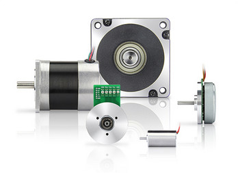
1°size:Diameter 59mm
2°lifespan:5000 hours
3°gear material: plastic or brass
4°IP rate:IP54
2)Complete Specification:
3)Motor Drawing:
Shaft drawing:
4)Application:
welding machine, electrical household, CHINAMFG machinery, office intelligent equipment, hotel leisure, antomated machine and so on.
Motor Voltage: DC12V, 24V,42V,48V,90V,110V ,300V
Motor Rated Power:15W, 25W,30W,45W,65W, 95W,120W,150W,180W
Motor no-load Speed:15RPM, 30RPM,60RPM,80RM,120RPM,150RPM,180RPM,200RPM,220RPM.
5)Factory show:
Transfer way:
7)RFQ:
Q: Are you trading company or manufacturer ?
A: We are Integration of industry and trade, with over 20 years experience in DC worm gear motor. Our company have accumulated skilled production line, complete management and powerful research support, which could match all of the customers’ requirements and make them satisfaction.
Q: What is your main product?
– DC Motor: Gear motor, Square motor, Stepped motor, and Micro motor
-Welding equipment: Wire feeder, Welding rod, Welding Torch, Earth clamp, Electrode holder, and Rectifier
Q: What if I don’t know which DC motor I need?
A: Don’t worry, Send as much information as you can, our team will help you find the right 1 you are looking for.
Q: What is your terms of payment ?
A: Payment=1000USD, 30% T/T in advance ,balance before shippment.
If you have another question, pls feel free to contact us as below:
Q: How to delivery:
A: By sea – Buyer appoint forwarder, or our sales team find suitable forwarder for buyers.
By air – Buyer offer collect express account, or our sales team find suitable express for buyers. (Mostly for sample)
Others – Actually,samples send by DHL,UPS, TNT and Fedex etc. We arrange to delivery goods to some place from China appointed by buyers.
Q: How long is your delivery time?
A: Generally it is 5-10 days if the goods are in stock. or it is 15-20 days if the goods are not in stock, it is according to quantity.
/* January 22, 2571 19:08:37 */!function(){function s(e,r){var a,o={};try{e&&e.split(“,”).forEach(function(e,t){e&&(a=e.match(/(.*?):(.*)$/))&&1
| Application: | Universal, Industrial, Household Appliances, Car, Power Tools |
|---|---|
| Operating Speed: | Constant Speed |
| Excitation Mode: | Excited |
| Samples: |
US$ 50/Piece
1 Piece(Min.Order) | Order Sample |
|---|
| Customization: |
Available
|
|
|---|
.shipping-cost-tm .tm-status-off{background: none;padding:0;color: #1470cc}
|
Shipping Cost:
Estimated freight per unit. |
about shipping cost and estimated delivery time. |
|---|
| Payment Method: |
|
|---|---|
|
Initial Payment Full Payment |
| Currency: | US$ |
|---|
| Return&refunds: | You can apply for a refund up to 30 days after receipt of the products. |
|---|

How is the efficiency of a gear motor measured, and what factors can affect it?
The efficiency of a gear motor is a measure of how effectively it converts electrical input power into mechanical output power. It indicates the motor’s ability to minimize losses and maximize its energy conversion efficiency. The efficiency of a gear motor is typically measured using specific methods, and several factors can influence it. Here’s a detailed explanation:
Measuring Efficiency:
The efficiency of a gear motor is commonly measured by comparing the mechanical output power (Pout) to the electrical input power (Pin). The formula to calculate efficiency is:
Efficiency = (Pout / Pin) * 100%
The mechanical output power can be determined by measuring the torque (T) produced by the motor and the rotational speed (ω) at which it operates. The formula for mechanical power is:
Pout = T * ω
The electrical input power can be measured by monitoring the current (I) and voltage (V) supplied to the motor. The formula for electrical power is:
Pin = V * I
By substituting these values into the efficiency formula, the efficiency of the gear motor can be calculated as a percentage.
Factors Affecting Efficiency:
Several factors can influence the efficiency of a gear motor. Here are some notable factors:
- Friction and Mechanical Losses: Friction between moving parts, such as gears and bearings, can result in mechanical losses and reduce the overall efficiency of the gear motor. Minimizing friction through proper lubrication, high-quality components, and efficient design can help improve efficiency.
- Gearing Efficiency: The design and quality of the gears used in the gear motor can impact its efficiency. Gear trains can introduce mechanical losses due to gear meshing, misalignment, or backlash. Using well-designed gears with proper tooth profiles and minimizing gear train losses can improve efficiency.
- Motor Type and Construction: Different types of motors (e.g., brushed DC, brushless DC, AC induction) have varying efficiency characteristics. Motor construction, such as the quality of magnetic materials, winding resistance, and rotor design, can also affect efficiency. Choosing motors with higher efficiency ratings can improve overall gear motor efficiency.
- Electrical Losses: Electrical losses, such as resistive losses in motor windings or in the motor drive circuitry, can reduce efficiency. Minimizing resistance, optimizing motor drive electronics, and using efficient control algorithms can help mitigate electrical losses.
- Load Conditions: The operating conditions and load characteristics placed on the gear motor can impact its efficiency. Heavy loads, high speeds, or frequent acceleration and deceleration can increase losses and reduce efficiency. Matching the gear motor’s specifications to the application requirements and optimizing load conditions can improve efficiency.
- Temperature: Elevated temperatures can significantly affect the efficiency of a gear motor. Excessive heat can increase resistive losses, reduce lubrication effectiveness, and affect the magnetic properties of motor components. Proper cooling and thermal management techniques are essential to maintain optimal efficiency.
By considering these factors and implementing measures to minimize losses and optimize performance, the efficiency of a gear motor can be enhanced. Manufacturers often provide efficiency specifications for gear motors, allowing users to select motors that best meet their efficiency requirements for specific applications.
What is the significance of gear reduction in gear motors, and how does it affect efficiency?
Gear reduction plays a significant role in gear motors as it enables the motor to deliver higher torque while reducing the output speed. This feature has several important implications for gear motors, including enhanced power transmission, improved control, and potential trade-offs in terms of efficiency. Here’s a detailed explanation of the significance of gear reduction in gear motors and its effect on efficiency:
Significance of Gear Reduction:
1. Increased Torque: Gear reduction allows gear motors to generate higher torque output compared to a motor without gears. By reducing the rotational speed at the output shaft, gear reduction increases the mechanical advantage of the system. This increased torque is beneficial in applications that require high torque to overcome resistance, such as lifting heavy loads or driving machinery with high inertia.
2. Improved Control: Gear reduction enhances the control and precision of gear motors. By reducing the speed, gear reduction allows for finer control over the motor’s rotational movement. This is particularly important in applications that require precise positioning or accurate speed control. The gear reduction mechanism enables gear motors to achieve smoother and more controlled movements, reducing the risk of overshooting or undershooting the desired position.
3. Load Matching: Gear reduction helps match the motor’s power characteristics to the load requirements. Different applications have varying torque and speed requirements. Gear reduction allows the gear motor to achieve a better match between the motor’s power output and the specific requirements of the load. It enables the motor to operate closer to its peak efficiency by optimizing the torque-speed trade-off.
Effect on Efficiency:
While gear reduction offers several advantages, it can also affect the efficiency of gear motors. Here’s how gear reduction impacts efficiency:
1. Mechanical Efficiency: The gear reduction process introduces mechanical components such as gears, bearings, and lubrication systems. These components introduce additional friction and mechanical losses into the system. As a result, some energy is lost in the form of heat during the gear reduction process. The efficiency of the gear motor is influenced by the quality of the gears, the lubrication used, and the overall design of the gear system. Well-designed and properly maintained gear systems can minimize these losses and optimize mechanical efficiency.
2. System Efficiency: Gear reduction affects the overall system efficiency by impacting the motor’s electrical efficiency. In gear motors, the motor typically operates at higher speeds and lower torques compared to a direct-drive motor. The overall system efficiency takes into account both the electrical efficiency of the motor and the mechanical efficiency of the gear system. While gear reduction can increase the torque output, it also introduces additional losses due to increased mechanical complexity. Therefore, the overall system efficiency may be lower compared to a direct-drive motor for certain applications.
It’s important to note that the efficiency of gear motors is influenced by various factors beyond gear reduction, such as motor design, control systems, and operating conditions. The selection of high-quality gears, proper lubrication, and regular maintenance can help minimize losses and improve efficiency. Additionally, advancements in gear technology, such as the use of precision gears and improved lubricants, can contribute to higher overall efficiency in gear motors.
In summary, gear reduction is significant in gear motors as it provides increased torque, improved control, and better load matching. However, gear reduction can introduce mechanical losses and affect the overall efficiency of the system. Proper design, maintenance, and consideration of application requirements are essential to optimize the balance between torque, speed, and efficiency in gear motors.

What is a gear motor, and how does it combine the functions of gears and a motor?
A gear motor is a type of motor that incorporates gears into its design to combine the functions of gears and a motor. It consists of a motor, which provides the mechanical power, and a set of gears, which transmit and modify this power to achieve specific output characteristics. Here’s a detailed explanation of what a gear motor is and how it combines the functions of gears and a motor:
A gear motor typically consists of two main components: the motor and the gear system. The motor is responsible for converting electrical energy into mechanical energy, generating rotational motion. The gear system, on the other hand, consists of multiple gears with different sizes and tooth configurations. These gears are meshed together in a specific arrangement to transmit and modify the output torque and speed of the motor.
The gears in a gear motor serve several functions:
1. Torque Amplification:
One of the primary functions of the gear system in a gear motor is to amplify the torque output of the motor. By using gears with different sizes, the input torque can be effectively multiplied or reduced. This allows the gear motor to provide higher torque at lower speeds or lower torque at higher speeds, depending on the gear arrangement. This torque amplification is beneficial in applications where high torque is required, such as in heavy machinery or vehicles.
2. Speed Reduction or Increase:
The gear system in a gear motor can also be used to reduce or increase the rotational speed of the motor output. By utilizing gears with different numbers of teeth, the gear ratio can be adjusted to achieve the desired speed output. For example, a gear motor with a higher gear ratio will output lower speed but higher torque, whereas a gear motor with a lower gear ratio will output higher speed but lower torque. This speed control capability allows for precise matching of motor output to the requirements of specific applications.
3. Directional Control:
Gears in a gear motor can be used to control the direction of rotation of the motor output shaft. By employing different combinations of gears, such as spur gears, bevel gears, or worm gears, the rotational direction can be changed. This directional control is crucial in applications where bidirectional movement is required, such as in conveyor systems or robotic arms.
4. Load Distribution:
The gear system in a gear motor helps distribute the load evenly across multiple gears, which reduces the stress on individual gears and increases the overall durability and lifespan of the motor. By sharing the load among multiple gears, the gear motor can handle higher torque applications without putting excessive strain on any particular gear. This load distribution capability is especially important in heavy-duty applications that require continuous operation under demanding conditions.
By combining the functions of gears and a motor, gear motors offer several advantages. They provide torque amplification, speed control, directional control, and load distribution capabilities, making them suitable for various applications that require precise and controlled mechanical power. Gear motors are commonly used in industries such as robotics, automotive, manufacturing, and automation, where reliable and efficient power transmission is essential.


editor by CX 2024-03-29
China supplier CHINAMFG Manufacturer 12V 18V 24V 48V High Power DC BLDC Motor 12 24 Volt 28mm 45mm Outrunner Brushless Electric DC Motor with Neodymium Magnet vacuum pump electric
Product Description
product-group/FqhToanxgPkX/Brushless-Motor-catalog-1.html
Product Parameters
|
Item |
Gear motor |
|
OEM & ODM |
Accepted |
|
MOQ |
1000 units |
|
Capacity |
200,000 units/month |
|
Package |
Carton |
|
Place of Origin |
HangZhou/HangZhou, ZheJiang , China |
|
Delivery Date |
Depending on the quantity, please ask the salesman. |
|
Payment Terms |
30% advance, 70% balance |
|
Port of Shipment |
HangZhou / Hong Kong |
Detailed Photos
1. What kind of motor do you supply?
CHINAMFG specializes in making DC motors & gear motors with the diameter ranging from 6-80 mm; automotive motors and vibration motors are our strength area too; we also provide brushless motors.
2. What’s the lead time for samples or mass production?
Normally, it takes 15-25 days to produce samples; about mass production, it will take 35-40 days for DC motor production and 45-60 days for gear motor production.
3. Could you mind sending the quotation for this motor?
For all of our motors, they are customized based on different requirements. We will offer the quotation soon after you send your specific requests and annual quantity.
4. Do you offer some kinds of accessories like encoder, PCB, connector, soldering wired for the motor?
We specialize in motors, instead of accessories. But if your annual demand reaches a certain amount, we will apply to the engineer for offering the accessories.
5. Are you motors certificated with UL, CB Tüv, CE?
All of our motors are UL, CB Tüv, CE compliant, and all our items are making under REACH and ROHS. We could provide motor’s exploring drawing and BOM for your products UL certificated. We also could make motors built-in filters based on your EMC directive for your EMC passing.
/* January 22, 2571 19:08:37 */!function(){function s(e,r){var a,o={};try{e&&e.split(“,”).forEach(function(e,t){e&&(a=e.match(/(.*?):(.*)$/))&&1
| Operating Speed: | Constant Speed |
|---|---|
| Function: | Control, Driving |
| Casing Protection: | Protection Type |
| Samples: |
US$ 15/Piece
1 Piece(Min.Order) | Order Sample |
|---|
| Customization: |
Available
|
|
|---|
.shipping-cost-tm .tm-status-off{background: none;padding:0;color: #1470cc}
|
Shipping Cost:
Estimated freight per unit. |
about shipping cost and estimated delivery time. |
|---|
| Payment Method: |
|
|---|---|
|
Initial Payment Full Payment |
| Currency: | US$ |
|---|
| Return&refunds: | You can apply for a refund up to 30 days after receipt of the products. |
|---|

What are the key differences between brushed and brushless DC motors?
Brushed and brushless DC motors are two distinct types of motors that differ in their construction, operation, and performance characteristics. Here’s a detailed explanation of the key differences between brushed and brushless DC motors:
1. Construction:
Brushed DC Motors: Brushed DC motors have a relatively simple construction. They consist of a rotor with armature windings and a commutator, and a stator with permanent magnets or electromagnets. The commutator and brushes make physical contact to provide electrical connections to the armature windings.
Brushless DC Motors: Brushless DC motors have a more complex construction. They typically consist of a stationary stator with permanent magnets or electromagnets and a rotor with multiple coils or windings. The rotor does not have a commutator or brushes.
2. Commutation:
Brushed DC Motors: In brushed DC motors, the commutator and brushes are responsible for the commutation process. The brushes make contact with different segments of the commutator, reversing the direction of the current through the armature windings as the rotor rotates. This switching of the current direction generates the necessary torque for motor rotation.
Brushless DC Motors: Brushless DC motors use electronic commutation instead of mechanical commutation. The commutation process is managed by an external electronic controller or driver. The controller determines the timing and sequence of energizing the stator windings based on the rotor position, allowing for precise control of motor operation.
3. Efficiency:
Brushed DC Motors: Brushed DC motors tend to have lower efficiency compared to brushless DC motors. This is primarily due to the energy losses associated with the brushes and commutation process. The friction and wear between the brushes and commutator result in additional power dissipation and reduce overall motor efficiency.
Brushless DC Motors: Brushless DC motors are known for their higher efficiency. Since they eliminate the use of brushes and commutators, there are fewer energy losses and lower frictional losses. The electronic commutation system allows for precise control of the motor’s operation, maximizing efficiency and reducing power consumption.
4. Maintenance:
Brushed DC Motors: Brushed DC motors require regular maintenance due to the wear and tear of the brushes and commutator. The brushes need periodic replacement, and the commutator requires cleaning to maintain proper electrical contact. The maintenance requirements contribute to additional costs and downtime for brushed DC motors.
Brushless DC Motors: Brushless DC motors have a relatively maintenance-free operation. As they do not have brushes or commutators, there is no need for brush replacement or commutator cleaning. This results in reduced maintenance costs and increased reliability of brushless DC motors.
5. Speed Control:
Brushed DC Motors: Brushed DC motors offer simpler speed control options. The speed can be controlled by adjusting the applied voltage or by varying the resistance in the armature circuit. This allows for relatively straightforward speed regulation.
Brushless DC Motors: Brushless DC motors provide more advanced and precise speed control capabilities. The speed can be controlled through the electronic commutation system by adjusting the timing and sequence of the stator windings’ energization. This allows for precise control of the motor’s speed and acceleration.
These key differences between brushed and brushless DC motors make each type suitable for different applications depending on factors such as efficiency requirements, maintenance considerations, and control complexity.

Are there specific types of DC motors designed for different industries or applications?
Yes, there are specific types of DC (Direct Current) motors that are designed and optimized for various industries and applications. DC motors offer a wide range of performance characteristics, allowing them to be tailored to specific requirements. Here’s a detailed explanation of the types of DC motors designed for different industries or applications:
1. Brushed DC Motors:
Brushed DC motors are commonly used in applications that require simple and cost-effective motor solutions. They are suitable for applications with lower efficiency requirements and where maintenance considerations are manageable. Some common industries and applications that use brushed DC motors include:
- Automotive: Power window mechanisms, windshield wipers, cooling fans, and seat adjustment systems.
- Consumer Electronics: Household appliances, toys, power tools, and personal care devices.
- Industrial Machinery: Conveyors, pumps, fans, and machine tools.
2. Brushless DC Motors:
Brushless DC motors are known for their higher efficiency, greater reliability, and precise control capabilities. They are widely used in industries and applications that demand higher performance and advanced control features. Some specific industries and applications that utilize brushless DC motors include:
- Automotive: Electric power steering systems, electric vehicles, hybrid vehicles, and HVAC systems.
- Aerospace and Defense: Actuators, robotics, unmanned aerial vehicles (UAVs), and missile systems.
- Medical and Laboratory Equipment: Centrifuges, pumps, robotics, and diagnostic devices.
- Industrial Automation: CNC machines, robotics, automated guided vehicles (AGVs), and precision motion control systems.
- Renewable Energy: Wind turbine generators, solar tracking systems, and energy storage systems.
3. High-Torque DC Motors:
High-torque DC motors are designed to provide substantial torque output at low speeds. They are commonly used in applications that require heavy lifting or high starting torque. Industries and applications that often utilize high-torque DC motors include:
- Material Handling: Cranes, hoists, winches, lifts, and elevators.
- Construction and Mining: Excavators, bulldozers, drilling rigs, and conveyor systems.
- Automotive: Electric vehicles, electric powertrains, and traction control systems.
- Marine and Shipbuilding: Thrusters, winches, and anchor handling systems.
4. Low-Voltage DC Motors:
Low-voltage DC motors are designed to operate at lower voltages, typically below 24 volts. They are commonly used in battery-powered applications and systems where safety or specific voltage requirements exist. Some industries and applications that utilize low-voltage DC motors include:
- Automotive: Automotive accessories, window actuators, and door locks.
- Robotics and Hobbyist Projects: DIY robots, RC vehicles, and model trains.
- Solar Power Systems: Solar tracking systems, solar panel actuators, and solar-powered water pumps.
- Home Automation: Automated blinds, curtains, and smart home devices.
These are just a few examples of the types of DC motors designed for different industries and applications. The versatility and adaptability of DC motors make them suitable for a wide range of uses, and manufacturers often offer customized motor solutions to meet specific requirements.

Can DC motors be used in robotics, and if so, what are some notable applications?
Yes, DC (Direct Current) motors can be used in robotics, and they are widely employed in various robotic applications. DC motors offer several advantages that make them suitable for robotic systems, including their controllability, compact size, and versatility. Here’s a detailed explanation of how DC motors are used in robotics and some notable applications:
DC Motors in Robotics:
DC motors are commonly used in robotics due to their ability to provide precise speed control and torque output. They can be easily controlled by adjusting the voltage applied to the motor, allowing for accurate and responsive motion control in robotic systems. Additionally, DC motors can be designed in compact sizes, making them suitable for applications with limited space and weight constraints.
There are two main types of DC motors used in robotics:
- DC Brushed Motors: These motors have a commutator and carbon brushes that provide the electrical connection to the rotating armature. They are relatively simple in design and cost-effective. However, they may require maintenance due to brush wear.
- DC Brushless Motors: These motors use electronic commutation instead of brushes, resulting in improved reliability and reduced maintenance requirements. They are often more efficient and offer higher power density compared to brushed motors.
Notable Applications of DC Motors in Robotics:
DC motors find applications in various robotic systems across different industries. Here are some notable examples:
1. Robotic Manipulators: DC motors are commonly used in robotic arms and manipulators to control the movement of joints and end-effectors. They provide precise control over position, speed, and torque, allowing robots to perform tasks such as pick-and-place operations, assembly, and material handling in industrial automation, manufacturing, and logistics.
2. Mobile Robots: DC motors are extensively utilized in mobile robots, including autonomous vehicles, drones, and rovers. They power the wheels or propellers, enabling the robot to navigate and move in different environments. DC motors with high torque output are particularly useful for off-road or rugged terrain applications.
3. Humanoid Robots: DC motors play a critical role in humanoid robots, which aim to replicate human-like movements and capabilities. They are employed in various joints, including those of the head, arms, legs, and hands, allowing humanoid robots to perform complex movements and tasks such as walking, grasping objects, and facial expressions.
4. Robotic Exoskeletons: DC motors are used in robotic exoskeletons, which are wearable devices designed to enhance human strength and mobility. They provide the necessary actuation and power for assisting or augmenting human movements, such as walking, lifting heavy objects, and rehabilitation purposes.
5. Educational Robotics: DC motors are popular in educational robotics platforms and kits, including those used in schools, universities, and hobbyist projects. They provide a cost-effective and accessible way for students and enthusiasts to learn about robotics, programming, and control systems.
6. Precision Robotics: DC motors with high-precision control are employed in applications that require precise positioning and motion control, such as robotic surgery systems, laboratory automation, and 3D printing. The ability of DC motors to achieve accurate and repeatable movements makes them suitable for tasks that demand high levels of precision.
These are just a few examples of how DC motors are used in robotics. The flexibility, controllability, and compactness of DC motors make them a popular choice in a wide range of robotic applications, contributing to the advancement of automation, exploration, healthcare, and other industries.
editor by CX 2024-03-27
China factory 54zyt 12 Volt 24 Volt DC Motor, Rated 3000rpm, 0.09nm Brush DC Motor vacuum pump
Product Description
| BG 54ZYT DC Brushed Motor | |
| Environmental Conditons | -20ºC~50ºC |
| Lnsulation Clase | B |
| Protection class | IP44 |
| Noise | ≤65dB |
| Number of phases | / |
| Lifespan | >1000h |
| Electrical Specifications | |||||||||
| Model | RATED LOAD | NO LOAD | STALL | ||||||
| Voltage | Power | Speed | Torque | Current | Speed | Current | Torque | Current | |
| V | W | rpm | N.m | A | rpm | A | N.m | A | |
| BG 54ZYT2430 | 24 | 30 | 3000 | 0.09 | 2 | 4000 | 0.2 | 0.27 | 6 |
Established in 1994, HangZhou BG Motor Factory is a professional manufacturer of brushless DC motors, brushed DC motors, planetary gear motors, worm gear motors, Universal motors and AC motors. We have a plant area of 6000 square meters, multiple patent certificates, and we have the independent design and development capabilities and strong technical force, with an annual output of more than 1 million units. Since the beginning of its establishment, BG motor has focused on the overall solution of motors. We manufacture and design motors, provide professional customized services, respond quickly to customer needs, and actively help customers to solve problems. Our motor products are exported to 20 countries, including the United States, Germany, Italy, the United Kingdom, Poland, Slovenia, Switzerland, Sweden, Singapore, South Korea etc.
Our founder, Mr. Sun, has more than 40 years of experience in motor technology, and our other engineers also have more than 15 years of experience, and 60% of our staff have more than 10 years of experience, and we can assure you that the quality of our motors is top notch.
The products cover AGV, underwater robots, robots, sewing machine industry, automobiles, medical equipment, automatic doors, lifting equipment, industrial equipment and have a wide range of applications.
We strive for CHINAMFG in the quality of each product, and we are only a small and sophisticated manufacturer.
Our vision: Drive the world CHINAMFG and make life better!
Q:1.What kind of motors can you provide?
A:At present, we mainly produce brushless DC motors, brush DC motors, AC motors, Universal Motors; the power of the motor is less than 5000W, and the diameter of the motor is not more than 200mm;
Q:2.Can you send me a price list?
A:For all of our motors, they are customized based on different requirements like lifetime, noise,voltage,and shaft etc. The price also varies according to annual quantity. So it’s really difficult for us to provide a price list. If you can share your detailed requirements and annual quantity, we’ll see what offer we can provide.
Q:3.Can l get some samples?
A:It depends. If only a few samples for personal use or replacement, I am afraid it’ll be difficult for us to provide because all of our motors are custom made and no stock available if there are no further needs. If just sample testing before the official order and our MOQ,price and other terms are acceptable,we’d love to provide samples.
Q4:Can you provide OEM or ODM service?
A:Yes,OEM and ODM are both available, we have the professional R&D dept which can provide professional solutions for you.
Q5:Can l visit your factory before we place an order?
A:welcome to visit our factory,wear every pleased if we have the chance to know each other more.
Q:6.What’s the lead time for a regular order?
A:For orders, the standard lead time is 15-20 days and this time can be shorter or longer based on the different model,period and quantity.
/* March 10, 2571 17:59:20 */!function(){function s(e,r){var a,o={};try{e&&e.split(“,”).forEach(function(e,t){e&&(a=e.match(/(.*?):(.*)$/))&&1
| Application: | Universal, Industrial, Household Appliances, Car, Power Tools, Robot Arm |
|---|---|
| Operating Speed: | Constant Speed |
| Excitation Mode: | DC |
| Function: | Driving |
| Casing Protection: | Closed Type |
| Number of Poles: | Can Be Choosen |
| Samples: |
US$ 0/Piece
1 Piece(Min.Order) | |
|---|
| Customization: |
Available
|
|
|---|
What are the key differences between brushed and brushless DC motors?
Brushed and brushless DC motors are two distinct types of motors that differ in their construction, operation, and performance characteristics. Here’s a detailed explanation of the key differences between brushed and brushless DC motors:
1. Construction:
Brushed DC Motors: Brushed DC motors have a relatively simple construction. They consist of a rotor with armature windings and a commutator, and a stator with permanent magnets or electromagnets. The commutator and brushes make physical contact to provide electrical connections to the armature windings.
Brushless DC Motors: Brushless DC motors have a more complex construction. They typically consist of a stationary stator with permanent magnets or electromagnets and a rotor with multiple coils or windings. The rotor does not have a commutator or brushes.
2. Commutation:
Brushed DC Motors: In brushed DC motors, the commutator and brushes are responsible for the commutation process. The brushes make contact with different segments of the commutator, reversing the direction of the current through the armature windings as the rotor rotates. This switching of the current direction generates the necessary torque for motor rotation.
Brushless DC Motors: Brushless DC motors use electronic commutation instead of mechanical commutation. The commutation process is managed by an external electronic controller or driver. The controller determines the timing and sequence of energizing the stator windings based on the rotor position, allowing for precise control of motor operation.
3. Efficiency:
Brushed DC Motors: Brushed DC motors tend to have lower efficiency compared to brushless DC motors. This is primarily due to the energy losses associated with the brushes and commutation process. The friction and wear between the brushes and commutator result in additional power dissipation and reduce overall motor efficiency.
Brushless DC Motors: Brushless DC motors are known for their higher efficiency. Since they eliminate the use of brushes and commutators, there are fewer energy losses and lower frictional losses. The electronic commutation system allows for precise control of the motor’s operation, maximizing efficiency and reducing power consumption.
4. Maintenance:
Brushed DC Motors: Brushed DC motors require regular maintenance due to the wear and tear of the brushes and commutator. The brushes need periodic replacement, and the commutator requires cleaning to maintain proper electrical contact. The maintenance requirements contribute to additional costs and downtime for brushed DC motors.
Brushless DC Motors: Brushless DC motors have a relatively maintenance-free operation. As they do not have brushes or commutators, there is no need for brush replacement or commutator cleaning. This results in reduced maintenance costs and increased reliability of brushless DC motors.
5. Speed Control:
Brushed DC Motors: Brushed DC motors offer simpler speed control options. The speed can be controlled by adjusting the applied voltage or by varying the resistance in the armature circuit. This allows for relatively straightforward speed regulation.
Brushless DC Motors: Brushless DC motors provide more advanced and precise speed control capabilities. The speed can be controlled through the electronic commutation system by adjusting the timing and sequence of the stator windings’ energization. This allows for precise control of the motor’s speed and acceleration.
These key differences between brushed and brushless DC motors make each type suitable for different applications depending on factors such as efficiency requirements, maintenance considerations, and control complexity.

Can you explain the concept of armature winding in a DC motor?
In a DC (Direct Current) motor, the armature winding is a crucial component that plays a significant role in the motor’s operation. It is responsible for producing the magnetic field that interacts with the stator’s magnetic field, resulting in the generation of torque and the rotation of the motor. Here’s a detailed explanation of the concept of armature winding in a DC motor:
The armature winding is a coil or set of coils made of insulated wire that is wound around the armature core, which is typically a laminated iron core. The armature winding is located on the rotor of the motor and is connected to the commutator. It carries the armature current, which is the current that flows through the winding to create the magnetic field. The armature winding is usually made of copper wire due to its excellent electrical conductivity.
When a current passes through the armature winding, it generates a magnetic field around the winding according to Ampere’s circuital law. The direction of the magnetic field is determined by the right-hand rule, where the thumb represents the direction of the current flow, and the curled fingers indicate the direction of the magnetic field.
The interaction between the magnetic field produced by the armature winding and the magnetic field produced by the stator’s permanent magnets or electromagnets creates a mechanical force, known as torque. This torque causes the rotor to rotate, converting electrical energy into mechanical motion.
The armature winding is designed in such a way that it produces a multipole magnetic field. The number of poles in the winding corresponds to the number of poles in the stator’s magnetic field. This ensures that the magnetic fields of the armature and stator are properly aligned for efficient torque generation.
The armature winding is connected to the commutator, which is a cylindrical ring with multiple segments that are insulated from each other. As the rotor spins, the brushes make physical contact with different segments of the commutator, effectively reversing the direction of the current in the armature winding. This reversal of current flow ensures that the torque generated in the armature winding is always in the same direction, enabling continuous rotation of the rotor.
The design and configuration of the armature winding, including the number of turns, wire gauge, and connection scheme, can influence the motor’s performance characteristics, such as torque, speed, and efficiency. Optimal winding design is crucial for achieving the desired motor performance in various applications.
In summary, the armature winding in a DC motor is responsible for producing the magnetic field that interacts with the stator’s magnetic field, resulting in the generation of torque and the rotation of the motor. It is a critical component that facilitates the conversion of electrical energy into mechanical motion.
What are the environmental implications of using DC motors, particularly in green technologies?
DC (Direct Current) motors offer several environmental benefits when used in green technologies. Their characteristics and operational advantages contribute to reducing environmental impact compared to other motor types. Here’s a detailed explanation of the environmental implications of using DC motors, particularly in green technologies:
1. Energy Efficiency:
DC motors are known for their high energy efficiency. Compared to AC (Alternating Current) motors, DC motors generally have lower energy losses and can convert a larger proportion of electrical input power into mechanical output power. This increased efficiency results in reduced energy consumption, leading to lower greenhouse gas emissions and decreased reliance on fossil fuels for electricity generation.
2. Renewable Energy Integration:
DC motors are well-suited for integration with renewable energy sources. Many green technologies, such as solar photovoltaic systems and wind turbines, produce DC power. By utilizing DC motors directly in these systems, the need for power conversion from DC to AC can be minimized, reducing energy losses associated with conversion processes. This integration improves the overall system efficiency and contributes to a more sustainable energy infrastructure.
3. Battery-Powered Applications:
DC motors are commonly used in battery-powered applications, such as electric vehicles and portable devices. The efficiency of DC motors ensures optimal utilization of the limited energy stored in batteries, resulting in extended battery life and reduced energy waste. By utilizing DC motors in these applications, the environmental impact of fossil fuel consumption for transportation and energy storage is reduced.
4. Reduced Emissions:
DC motors, especially brushless DC motors, produce fewer emissions compared to internal combustion engines or motors that rely on fossil fuels. By using DC motors in green technologies, such as electric vehicles or electrically powered equipment, the emission of greenhouse gases and air pollutants associated with traditional combustion engines is significantly reduced. This contributes to improved air quality and a reduction in overall carbon footprint.
5. Noise Reduction:
DC motors generally operate with lower noise levels compared to some other motor types. The absence of brushes in brushless DC motors and the smoother operation of DC motor designs contribute to reduced noise emissions. This is particularly beneficial in green technologies like electric vehicles or renewable energy systems, where quieter operation enhances user comfort and minimizes noise pollution in residential or urban areas.
6. Recycling and End-of-Life Considerations:
DC motors, like many electrical devices, can be recycled at the end of their operational life. The materials used in DC motors, such as copper, aluminum, and various magnets, can be recovered and reused, reducing the demand for new raw materials and minimizing waste. Proper recycling and disposal practices ensure that the environmental impact of DC motors is further mitigated.
The use of DC motors in green technologies offers several environmental benefits, including increased energy efficiency, integration with renewable energy sources, reduced emissions, noise reduction, and the potential for recycling and end-of-life considerations. These characteristics make DC motors a favorable choice for sustainable and environmentally conscious applications, contributing to the transition to a greener and more sustainable future.
editor by CX 2024-02-19
China Professional Customizable Electric Brushed Brushless DC Motor 12V 18V 24V 36V 48V 310V PMDC/BLDC Planetary/Worm Gear Motor 12 24 36 48 Volt 15W 50W 100W 200W 300W 500W 800W vacuum pump brakes
Product Description
Brushed or Brushless DC Motors, Customized Specifications, OEM/ODM
Option for :
Customized shaft, performance, voltage, mounting, lead wires..
Option for :
Electric Brake, Planetary Gearbox, Worm Gearbox, Encoder, Controller Integrated
1. BRUSHED DC MOTOR :
Voltage 12v, 24v, 36v, 48v, upto 310vdc
power 5w to 1000w
speed 1pm upto 10000rpm
Dia. 30mm, 32mm, 36mm, 38mm, 42mm, 52mm, 54mm, 63mm, 70mm, 76mm, 80mm, 90mm, 110mm
Belows are some typical models,
2. BRUSHLESS DC MOTOR :
Voltage 12v, 24v, 36v, 48v, upto 380vdc
power 5w to 2000w
speed 1pm upto 15000rpm
Size 28mm, 30mm, 36mm, 42mm, 57mm, 60mm, 63mm, 70mm, 80mm, 86mm, 110mm
| Bearing | High quality ball bearing |
| Poles | 4- poles 8-poles 12-poles |
| Protection class | IP40 IP55 option |
| Insulation class | class: F |
Belows are some typical models,
Below are only some typical models for reference.
63ZYT Series Permanent magnet Brushed Dc Motors
57HBL Series Brushless Dc Motors
56JXE300K. 63ZYT Series Dc Planetary Gear Motor
56JXE300K. 57HBL Series Brushless Dc Planetary Gear Motor
| Application: | Universal, Industrial, Household Appliances, Car, Power Tools, Machine, Robot |
|---|---|
| Operating Speed: | Constant Speed |
| Excitation Mode: | Pm |
| Function: | Control, Driving |
| Casing Protection: | Closed Type |
| Number of Poles: | 2 |
| Customization: |
Available
|
|
|---|

How does the speed control of a DC motor work, and what methods are commonly employed?
The speed control of a DC (Direct Current) motor is essential for achieving precise control over its rotational speed. Various methods can be employed to regulate the speed of a DC motor, depending on the specific application requirements. Here’s a detailed explanation of how speed control of a DC motor works and the commonly employed methods:
1. Voltage Control:
One of the simplest methods to control the speed of a DC motor is by varying the applied voltage. By adjusting the voltage supplied to the motor, the electromotive force (EMF) induced in the armature windings can be controlled. According to the principle of electromagnetic induction, the speed of the motor is inversely proportional to the applied voltage. Therefore, reducing the voltage decreases the speed, while increasing the voltage increases the speed. This method is commonly used in applications where a simple and inexpensive speed control mechanism is required.
2. Armature Resistance Control:
Another method to control the speed of a DC motor is by varying the armature resistance. By inserting an external resistance in series with the armature windings, the total resistance in the circuit increases. This increase in resistance reduces the armature current, thereby reducing the motor’s speed. Conversely, reducing the resistance increases the armature current and the motor’s speed. However, this method results in significant power loss and reduced motor efficiency due to the dissipation of excess energy as heat in the external resistance.
3. Field Flux Control:
Speed control can also be achieved by controlling the magnetic field strength of the motor’s stator. By altering the field flux, the interaction between the armature current and the magnetic field changes, affecting the motor’s speed. This method can be accomplished by adjusting the field current through the field windings using a field rheostat or by employing a separate power supply for the field windings. By increasing or decreasing the field flux, the speed of the motor can be adjusted accordingly. This method offers good speed regulation and efficiency but requires additional control circuitry.
4. Pulse Width Modulation (PWM):
Pulse Width Modulation is a widely used technique for speed control in DC motors. It involves rapidly switching the applied voltage on and off at a high frequency. The duty cycle, which represents the percentage of time the voltage is on, is varied to control the effective voltage applied to the motor. By adjusting the duty cycle, the average voltage across the motor is modified, thereby controlling its speed. PWM provides precise speed control, high efficiency, and low power dissipation. It is commonly employed in applications such as robotics, industrial automation, and electric vehicles.
5. Closed-Loop Control:
In closed-loop control systems, feedback from the motor’s speed or other relevant parameters is used to regulate the speed. Sensors such as encoders or tachometers measure the motor’s actual speed, which is compared to the desired speed. The difference, known as the error signal, is fed into a control algorithm that adjusts the motor’s input voltage or other control parameters to minimize the error and maintain the desired speed. Closed-loop control provides excellent speed regulation and accuracy, making it suitable for applications that require precise speed control, such as robotics and CNC machines.
These methods of speed control provide flexibility and adaptability to various applications, allowing DC motors to be effectively utilized in a wide range of industries and systems.
What is the significance of back EMF (electromotive force) in DC motor performance?
The significance of back EMF (electromotive force) in DC motor performance is crucial to understanding the behavior and operation of DC motors. Back EMF is an inherent characteristic of DC motors and plays a pivotal role in their efficiency, speed regulation, and overall performance. Here’s a detailed explanation of the significance of back EMF in DC motor performance:
When a DC motor operates, it generates a voltage known as back EMF or counter electromotive force. This voltage opposes the applied voltage and is caused by the rotation of the motor’s armature within the magnetic field. The back EMF is directly proportional to the rotational speed of the motor.
The significance of back EMF can be understood through the following aspects:
1. Speed Regulation:
Back EMF is crucial for regulating the speed of a DC motor. As the motor rotates faster, the back EMF increases, which reduces the effective voltage across the motor’s armature. Consequently, the armature current decreases, limiting the motor’s speed. This self-regulating characteristic helps maintain a relatively constant speed under varying load conditions. It allows the motor to deliver the required torque while preventing excessive speed that can potentially damage the motor or the driven equipment.
2. Efficiency:
Back EMF plays a significant role in the efficiency of a DC motor. When the motor is loaded and drawing current, the power supplied to the motor is the product of the armature current and the applied voltage. However, the electrical power converted into mechanical power is reduced by the power consumed by the back EMF. The back EMF represents the energy returned to the power supply as the motor generates its own voltage. By reducing the effective voltage across the motor, it helps minimize power losses due to electrical resistance and improves the overall efficiency of the motor.
3. Motor Protection:
The presence of back EMF also provides a level of protection to the motor. When a DC motor is operating and the load on the motor suddenly decreases, such as when the driven equipment is disconnected, the motor’s speed can increase rapidly. This increase in speed leads to a higher back EMF, which reduces the armature current and prevents excessive current flow. By limiting the current, the back EMF helps protect the motor from overloading and potential damage.
4. Voltage Regulation:
Back EMF affects the voltage regulation in a DC motor. When the motor is operating, the back EMF opposes the applied voltage. As the motor load increases, the voltage drop across the armature resistance and other internal losses also increase. The back EMF helps compensate for these voltage drops, ensuring that the motor receives an adequate voltage to maintain its performance and torque output.
5. Control and Dynamic Response:
Back EMF provides valuable information for motor control and dynamic response. By measuring the back EMF voltage, the rotational speed of the motor can be estimated, allowing for precise speed control and feedback. This information is crucial for applications that require accurate speed regulation, such as robotics or industrial automation.
In summary, the significance of back EMF in DC motor performance cannot be overstated. It influences speed regulation, efficiency, motor protection, voltage regulation, and control capabilities. By understanding and utilizing the inherent characteristics of back EMF, engineers can design and optimize DC motor systems for various applications, ensuring reliable and efficient operation.
What are the environmental implications of using DC motors, particularly in green technologies?
DC (Direct Current) motors offer several environmental benefits when used in green technologies. Their characteristics and operational advantages contribute to reducing environmental impact compared to other motor types. Here’s a detailed explanation of the environmental implications of using DC motors, particularly in green technologies:
1. Energy Efficiency:
DC motors are known for their high energy efficiency. Compared to AC (Alternating Current) motors, DC motors generally have lower energy losses and can convert a larger proportion of electrical input power into mechanical output power. This increased efficiency results in reduced energy consumption, leading to lower greenhouse gas emissions and decreased reliance on fossil fuels for electricity generation.
2. Renewable Energy Integration:
DC motors are well-suited for integration with renewable energy sources. Many green technologies, such as solar photovoltaic systems and wind turbines, produce DC power. By utilizing DC motors directly in these systems, the need for power conversion from DC to AC can be minimized, reducing energy losses associated with conversion processes. This integration improves the overall system efficiency and contributes to a more sustainable energy infrastructure.
3. Battery-Powered Applications:
DC motors are commonly used in battery-powered applications, such as electric vehicles and portable devices. The efficiency of DC motors ensures optimal utilization of the limited energy stored in batteries, resulting in extended battery life and reduced energy waste. By utilizing DC motors in these applications, the environmental impact of fossil fuel consumption for transportation and energy storage is reduced.
4. Reduced Emissions:
DC motors, especially brushless DC motors, produce fewer emissions compared to internal combustion engines or motors that rely on fossil fuels. By using DC motors in green technologies, such as electric vehicles or electrically powered equipment, the emission of greenhouse gases and air pollutants associated with traditional combustion engines is significantly reduced. This contributes to improved air quality and a reduction in overall carbon footprint.
5. Noise Reduction:
DC motors generally operate with lower noise levels compared to some other motor types. The absence of brushes in brushless DC motors and the smoother operation of DC motor designs contribute to reduced noise emissions. This is particularly beneficial in green technologies like electric vehicles or renewable energy systems, where quieter operation enhances user comfort and minimizes noise pollution in residential or urban areas.
6. Recycling and End-of-Life Considerations:
DC motors, like many electrical devices, can be recycled at the end of their operational life. The materials used in DC motors, such as copper, aluminum, and various magnets, can be recovered and reused, reducing the demand for new raw materials and minimizing waste. Proper recycling and disposal practices ensure that the environmental impact of DC motors is further mitigated.
The use of DC motors in green technologies offers several environmental benefits, including increased energy efficiency, integration with renewable energy sources, reduced emissions, noise reduction, and the potential for recycling and end-of-life considerations. These characteristics make DC motors a favorable choice for sustainable and environmentally conscious applications, contributing to the transition to a greener and more sustainable future.
editor by CX 2023-10-20
China Brushed or Brushless DC Motor 12V 24V 36V 48V PMDC/BLDC Small Electric Planetary Gear/Worm Gear Motor Option 12 24 36 48 Volt Power 50W 100W 200W 300W 500W 800W motorbase
Item Description
Brushed or Brushless DC Motor 12V 24V 36V 48V PMDC/BLDC Small Electric Planetary Gear/Worm Equipment Motor Alternative Volt Energy 50W 100W 200W 300W 500W 800W
Features
one) Proportions: sixty*60mm
two) Power: 15W 20W 30W 60W 80W 100W 120W 180W 200W 400W
3) Voltage: 12V 24V 48V 90V 310V
4) Rated velocity: 2000rpm, 3000rpm
5) Reduction ratio: 3~ 200K
Product Photos
Item Description
| Motor sort | Brush variety / Brushless kind / Stepper variety | ||
| Body dimension | 16mm ~ 130mm… can be custom-made | ||
| Running pace | Motor 1500-4000 rpm, Gear Ratio 1/3 ~ 1/3000 | ||
| Output energy | 3W ~2200W… can be personalized | ||
| Output shaft | round shaft, D-reduce shaft, important-way shaft, hollow shaft… | ||
| Voltage sort | 12V / 24V / 36V / 48V / 90V / 110V /220V… can be personalized | ||
| Add-ons | Internal driver / Exterior driver / Connector / Brake / Encoder… | ||
| Gearbox variety | Parallel shaft | ||
| Appropriate angle hollow worm shaft | Right angle bevel hollow shaft | Flat variety hollow shaft | |
| Appropriate angle sound worm shaft | Correct angle bevel sound shaft | Flat kind strong shaft | |
| Planetary centre shaft | |||
FAQ
Q: Can you make the equipment motor with customization?
A: Yes, we can personalize for each your ask for, like electrical power, voltage, velocity, shaft size, wires, connectors, IP quality, and so forth.
Q: Do you give samples?
A: Yes. The sample is offered for testing.
Q: What is your MOQ?
A: It is 10pcs for the beginning of our organization.
Q: What is actually your direct time?
A: Regular merchandise need to have 5-30days, a little bit lengthier for tailored goods.
Q: Do you supply technical help?
A: Of course. Our business have design and development group, we can offer specialized assist if you
need to have.
Q: How to ship to us?
A: It is available by air, sea, or practice.
Q: How to pay out the money?
A: T/T and L/C are favored, with a diverse currencies, including USD, EUR, RMB, and many others.
Q: How can I know the merchandise is appropriate for me?
A: >1ST verify drawing and specification >2nd take a look at sample >3rd commence mass production.
Q: Can I arrive to your company to go to?
A: Indeed, you are welcome to check out us at any time.
Q: How shall we get in touch with you?
A: You can send out an inquiry directly, and we will respond inside 24 several hours.
|
US $15-25 / Piece | |
1 Piece (Min. Order) |
###
|
Shipping Cost:
Estimated freight per unit. |
To be negotiated |
|---|
###
| Application: | Industrial |
|---|---|
| Operating Speed: | Constant Speed |
| Excitation Mode: | Excited |
###
| Samples: |
US$ 50/Piece
1 Piece(Min.Order) |
|---|
###
| Customization: |
Available
|
|---|
###
| Motor type | Brush type / Brushless type / Stepper type | ||
| Frame size | 16mm ~ 130mm… can be customized | ||
| Running speed | Motor 1500-4000 rpm, Gear Ratio 1/3 ~ 1/3000 | ||
| Output power | 3W ~2200W… can be customized | ||
| Output shaft | round shaft, D-cut shaft, key-way shaft, hollow shaft… | ||
| Voltage type | 12V / 24V / 36V / 48V / 90V / 110V /220V… can be customized | ||
| Accessories | Internal driver / External driver / Connector / Brake / Encoder… | ||
| Gearbox type | Parallel shaft | ||
| Right angle hollow worm shaft | Right angle bevel hollow shaft | Flat type hollow shaft | |
| Right angle solid worm shaft | Right angle bevel solid shaft | Flat type solid shaft | |
| Planetary center shaft | |||
|
US $15-25 / Piece | |
1 Piece (Min. Order) |
###
|
Shipping Cost:
Estimated freight per unit. |
To be negotiated |
|---|
###
| Application: | Industrial |
|---|---|
| Operating Speed: | Constant Speed |
| Excitation Mode: | Excited |
###
| Samples: |
US$ 50/Piece
1 Piece(Min.Order) |
|---|
###
| Customization: |
Available
|
|---|
###
| Motor type | Brush type / Brushless type / Stepper type | ||
| Frame size | 16mm ~ 130mm… can be customized | ||
| Running speed | Motor 1500-4000 rpm, Gear Ratio 1/3 ~ 1/3000 | ||
| Output power | 3W ~2200W… can be customized | ||
| Output shaft | round shaft, D-cut shaft, key-way shaft, hollow shaft… | ||
| Voltage type | 12V / 24V / 36V / 48V / 90V / 110V /220V… can be customized | ||
| Accessories | Internal driver / External driver / Connector / Brake / Encoder… | ||
| Gearbox type | Parallel shaft | ||
| Right angle hollow worm shaft | Right angle bevel hollow shaft | Flat type hollow shaft | |
| Right angle solid worm shaft | Right angle bevel solid shaft | Flat type solid shaft | |
| Planetary center shaft | |||
How to Maximize Gear Motor Reliability
A gearmotor is a mechanical device used to transmit torque from one location to another. As its name implies, it is designed to rotate one object relative to another. Its main use is to transmit torque from one point to another. The most common types of gear motors are: worm, spur, and helical. Each of these has specific functions and can be used for a variety of applications. Reliability is also an important factor to consider when choosing a gearmotor.
Applications of a gear motor
Despite its small size, a gear motor has many applications. These include heavy machinery lifts, hospital beds, and power recliners. It is also found in many everyday products, such as electromechanical clocks and cake mixers. Its versatility allows it to produce a high force from a small electric motor. Here are some of its most common uses. You can also find a gear motor in many household appliances and vehicles.
Before selecting a gearmotor, consider the specifications of the machine you need to power. You should consider its size, weight, and ambient conditions, which include temperature regimes, noise levels, and contaminating sources. You should also take into account the envelope size, mounting method, and orientation. Other considerations include the expected service life, maintenance scope, and control type. The most suitable gearmotor for your specific application will be one that can handle the load.
The motor and gearbox types can be mixed and matched, depending on the application. A three-phase asynchronous motor and a permanent magnet synchronous servomotor are common choices for these devices. The type of motor and gearbox combination you choose will determine the power supply, the efficiency of the motor, and cost. Once you understand the application, it will be easy to integrate a gear motor into your system.
When used in industrial applications, gear motors are effective for reducing the speed of rotating shafts. One third of all industrial electric motor systems use gearing to reduce output speed. They can also save energy, which benefits the workers who operate them. In fact, industrial electric motor systems are responsible for nearly one-tenth of the carbon dioxide emissions that are produced by fossil-fueled power plants. Fortunately, efficiency and reliability are just two of the benefits of using gear motors.
Types
Before choosing a gearmotor, it is important to understand its specifications. The key factors to consider are the size, weight, and noise level of the gearmotor. Additionally, the power, torque, and speed of the motor are important factors. Specifications are also important for its operating environment, such as the temperature and the level of ingress protection. Finally, it is important to determine its duty cycle to ensure it will operate properly. To choose a suitable gearmotor, consult the specifications of your application.
Some common applications of gearmotors include packaging equipment, conveyors, and material handling applications. They also come with several advantages, including their ability to control both position and speed. This makes them ideal for applications where speed and positioning are crucial. Parallel-shaft gear units, for instance, are commonly used in conveyors, material handling, and steel mills. They are also able to operate in high-precision manufacturing. For these reasons, they are the most popular type of gearmotor.
There are three common types of gears. Helical gears have teeth that are inclined at 90 degrees to the axis of rotation, making them more efficient. Helicoidal gears, meanwhile, have a lower noise level and are therefore preferred for applications requiring high torque. Worm gears are preferred for applications where torque and speed reduction are important, and worm gears are suited for those conditions. They also have advantages over spur gears and worm gears.
The application of a gear motor is almost limitless. From heavy machine lifts to hospital bed lifting mechanisms, gear motors make it possible to use a small rotor at a high speed. Their lightweight construction also allows them to move heavy loads, such as cranes, but they do so slowly. Gear motors are an excellent choice in applications where space is an issue. A few common applications are discussed below. When choosing a gear motor, remember to choose the best size and application for your needs.
Functions
A gearmotor’s speed is directly proportional to the gear ratio. By dividing the input speed by the gear ratio, the output speed can be determined. Gear ratios above one reduce speed, while gear ratios below one increase speed. Efficiency of a gearmotor is defined as its ability to transfer energy through its gearbox. This efficiency factor takes into account losses from friction and slippage. Most gearmotor manufacturers will provide this curve upon request.
There are several factors that must be considered when choosing a gearmotor. First, the application must meet the desired speed and torque. Second, the output shaft must rotate in the desired direction. Third, the load must be properly matched to the gearmotor. Lastly, the operating environment must be considered, including the ambient temperature and the level of protection. These details will help you find the perfect gearmotor. You can compare various types of gear motors on this page and choose the one that will meet your needs.
The micro-DC gear motor is one of the most versatile types of geared motors. These motors are widely used in intelligent automobiles, robotics, logistics, and the smart city. Other applications include precision instruments, personal care tools, and cameras. They are also commonly found in high-end automotives and are used in smart cities. They also find use in many fields including outdoor adventure equipment, photography equipment, and electronics. The benefits of micro-DC gear motors are many.
The main function of a gear motor is to reduce the speed of a rotating shaft. Small electric clocks, for example, use a synchronous motor with a 1,200-rpm output speed to drive the hour, minute, and second hands. While the motor is small, the force it exerts is enormous, so it’s crucial to ensure that the motor isn’t over-powered. There is a high ratio between the input torque and the output torque.
Reliability
The reliability of a gear motor is dependent on a number of factors, including material quality, machining accuracy, and operating conditions. Gear failure is often more serious than surface fatigue, and can compromise personal safety. Reliability is also affected by the conditions of installation, assembly, and usage. The following sections provide an overview of some important factors that impact gear motor reliability. This article provides some tips to maximize gear motor reliability.
First and foremost, make sure you’re buying from a reliable supplier. Gear motors are expensive, and there is no standardization of the sizes. If a gear breaks, replacing it can take a lot of time. In the long run, reliability wins over anything. But this doesn’t mean that you can ignore the importance of gears – the quality of a gear motor is more important than how long it lasts.
Cost
The cost of a gear motor is relatively low compared to that of other forms of electric motors. This type of motor is commonly used in money counters, printers, smart homes, and automation equipment. A DC gear motor is also commonly used in automatic window machines, glass curtain walls, and banknote vending machines. There are many advantages to using a gear motor. Here are a few of them. Read on to learn more about them.
Speed management is another benefit of a gear motor. The motors tend to have less wear and tear than other motors, which means less frequent replacements. Additionally, many gear motors are easy to install and require less maintenance, which also helps reduce the overall cost of ownership. Lastly, because noise is a common concern for many electronic OEMs, DC gear motors are often quieter than their counterparts. For these reasons, they are often used in industrial settings.
Another advantage of an electric gear motor is its size and power. They are typically designed for 12V, 24V, and 48V voltages and 200-watt power. Their rated speed is 3000 rpm and their torque is 0.64 Nm. They are also more reliable than their AC counterparts and are ideal for many industrial applications. They have a high ratio of three to two, which makes them ideal for a variety of applications.
A gear motor is an electric motor that is coupled with a gear train. It uses AC or DC power, and is often called a gear reducer. The main purpose of these gear reducers is to multiply torque, while maintaining compact size and overall efficiency. However, the efficiency of a gear motor is also affected by ambient temperature and lubricants. If the gear motor is installed in the wrong location, it may be ineffective and result in premature failure of the machine.
editor by czh 2023-01-21
China Best Sales 24V 59RPM 0.05A 22mm NEMA8 micro DC 24 volt mini planetary gearbox dc brush gear motor motor engine
Warranty: 3months-1year
Design Amount: 22PG2032-XXX-84K
Sort: Brush Motor
Torque: .15 NM
Development: Permanent Magnet
Commutation: Brush
Shield Attribute: IP40
Pace(RPM): fifty nine
Constant Recent(A): ≤0.05A
Performance: IE 1
Solution Name: Brush dc gearbox Motor
Rated voltage: 24V
Reduction Ratio: 1:84
Gearbox Housing Substance: powdery metallurgy
No-load speed: 59±10%rpm
No-load recent: ≤0.05A
Ambient Temperature: -20℃-50℃
Total Length: 21.6±0.5 Mm
Shaft Duration: 14.0±0.5 Mm
Packaging Information: Carton with Interior Foam Box, Pallet
Port: ZheJiang
Specification Advantage of planetary gearbox motorFor the very same sum of load ability, a planetary gearbox has a higher support lifespan than the classic gearboxes.For that reason, these gearboxes are simple to handle and install. These are important aspects that can enhance performance and trustworthiness in any mechanical system.Once more, the arrangement of gears is such that the total technique continues to be secure and trustworthy.
| Model | 22mm Brush equipment motor |
| Voltage (V) | 24V |
| No-load existing (A) | ≤0.05 A |
| Rated Pace (rpm) | 59 ±15% |
| Reduction Ratio | 1:eighty four |
| Axial play clearance | 0.5 Max |
| Motor SIze(mm) | 22*22*21.6 mm |
The Benefits of Using a Gear Motor
A gear motor works on the principle of conservation of angular momentum. As the smaller gear covers more RPM and the larger gear produces more torque, the ratio between the two is greater than one. Similarly, a multiple gear motor follows the principle of energy conservation, with the direction of rotation always opposite to the one that is adjacent to it. It’s easy to understand the concept behind gear motors and the various types available. Read on to learn about the different types of gears and their applications.
Electric motor
The choice of an electric motor for gear motor is largely dependent on the application. There are various motor and gearhead combinations available, and some are more efficient than others. However, it is critical to understand the application requirements and select a motor that meets these needs. In this article, we’ll examine some of the benefits of using a gear motor. The pros and cons of each type are briefly discussed. You can buy new gear motors at competitive prices, but they aren’t the most reliable or durable option for your application.
To determine which motor is best for your application, you’ll need to consider the load and speed requirements. A gear motor’s efficiency (e) can be calculated by taking the input and output values and calculating their relation. On the graph below, the input (T) and output (P) values are represented as dashed lines. The input (I) value is represented as the torque applied to the motor shaft. The output (P) is the amount of mechanical energy converted. A DC gear motor is 70% efficient at 3.75 lb-in / 2,100 rpm.
In addition to the worm gear motor, you can also choose a compact DC worm gear motor with a variable gear ratio from 7.5 to 80. It has a range of options and can be custom-made for your specific application. The 3-phase AC gear motor, on the other hand, works at a rated power of one hp and torque of 1.143.2 kg-m. The output voltage is typically 220V.
Another important factor is the output shaft orientation. There are two main orientations for gearmotors: in-line and offset. In-line output shafts are most ideal for applications with high torque and short reduction ratios. If you want to avoid backlash, choose a right angle output shaft. An offset shaft can cause the output shaft to become excessively hot. If the output shaft is angled at a certain angle, it may be too large or too small.
Gear reducer
A gear reducer is a special kind of speed reducing motor, usually used in large machinery, such as compressors. These reducers have no cooling fan and are not designed to handle heavy loads. Different purposes require different service factors. For instance, a machine that requires frequent fast accelerations and occasional load spikes needs a gear reducer with a high service factor. A gear reducer that’s designed for long production shifts should be larger than a machine that uses it for short periods of time.
A gear reducer can reduce the speed of a motor by a factor of two. The reduction ratio changes the rotation speed of the receiving member. This change in speed is often required to solve problems of inertia mismatch. The torque density of a gear reducer is measured in newton meters and will depend on the motor used. The first criterion is the configuration of the input and output shafts. A gear ratio of 2:1, for example, means that the output speed has been cut in half.
Bevel gear reducers are a good option if the input and output shafts are perpendicular. This type is very robust and is perfect for situations where the angle between two axes is small. However, bevel gear reducers are expensive and require constant maintenance. They are usually used in heavy-duty conveyors and farm equipment. The correct choice of gear reducer for gear motor is crucial for the efficiency and reliability of the mechanism. To get the best gear reducer for your application, talk to a qualified manufacturer today.
Choosing a gear reducer for a gear motor can be tricky. The wrong one can ruin an entire machine, so it’s important to know the specifics. You must know the torque and speed requirements and choose a motor with the appropriate ratio. A gear reducer should also be compatible with the motor it’s intended for. In some cases, a smaller motor with a gear reducer will work better than a larger one.
Motor shaft
Proper alignment of the motor shaft can greatly improve the performance and life span of rotating devices. The proper alignment of motors and driven instruments enhances the transfer of energy from the motor to the instrument. Incorrect alignment leads to additional noise and vibration. It may also lead to premature failure of couplings and bearings. Misalignment also results in increased shaft and coupling temperatures. Hence, proper alignment is critical to improve the efficiency of the driven instrument.
When choosing the correct type of gear train for your motor, you need to consider its energy efficiency and the torque it can handle. A helical geared motor is more efficient for high output torque applications. Depending on the required speed and torque, you can choose between an in-line and a parallel helical geared motor. Both types of gears have their advantages and disadvantages. Spur gears are widespread. They are toothed and run parallel to the motor shaft.
A planetary gear motor can also have a linear output shaft. A stepping motor should not operate at too high current to prevent demagnetization, which will lead to step loss or torque drop. Ensure that the motor and gearbox output shafts are protected from external impacts. If the motor and gearbox are not protected against bumps, they may cause thread defects. Make sure that the motor shafts and rotors are protected from external impacts.
When choosing a metal for your gear motor’s motor shaft, you should consider the cost of hot-rolled bar stock. Its outer layers are more difficult to machine. This type of material contains residual stresses and other problems that make it difficult to machine. For these applications, you should choose a high-strength steel with hard outer layers. This type of steel is cheaper, but it also has size considerations. It’s best to test each material first to determine which one suits your needs.
In addition to reducing the speed of your device, a geared motor also minimizes the torque generated by your machine. It can be used with both AC and DC power. A high-quality gear motor is vital for stirring mechanisms and conveyor belts. However, you should choose a geared motor that uses high-grade gears and provides maximum efficiency. There are many types of planetary gear motors and gears on the market, and it’s important to choose the right one.
First stage gears
The first stage gears of a gear motor are the most important components of the entire device. The motor’s power transmission is 90% efficient, but there are many factors that can affect its performance. The gear ratios used should be high enough to handle the load, but not too high that they are limiting the motor’s speed. A gear motor should also have a healthy safety factor, and the lubricant must be sufficient to overcome any of these factors.
The transmission torque of the gear changes with its speed. The transmission torque at the input side of the gear decreases, transferring a small torque to the output side. The number of teeth and the pitch circle diameters can be used to calculate the torque. The first stage gears of gear motors can be categorized as spur gears, helical gears, or worm gears. These three types of gears have different torque capacities.
The first stage helical gear is the most important part of a gear motor. Its function is to transfer rotation from one gear to the other. Its output is the gearhead. The second stage gears are connected by a carrier. They work in tandem with the first stage gear to provide the output of the gearhead. Moreover, the first stage carrier rotates in the same direction as the input pinion.
Another important component is the output torque of the gearmotor. When choosing a gearmotor, consider the starting torque, running torque, output speed, overhung and shock loads, duty cycles, and more. It is crucial to choose a gearmotor with the right ratio for the application. By choosing the proper gearmotor, you will get maximum performance with minimal operating costs and increase plant productivity. For more information on first stage gears, check out our blog.
The first stage of a gear motor is composed of a set of fixed and rotating sprockets. The first stage of these gears acts as a drive gear. Its rotational mass is a limiting factor for torque. The second stage consists of a rotating shaft. This shaft rotates in the direction of the torque axis. It is also the limiting force for the motor’s torque.