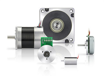
Product Description
Product Parameters
Model No.:RK-571SH-10360-23.2
Size details:
Motor Diameter: φ17.1mm
Motor housing length: 17.8mm
Shaft length: customization
Specifications:
Rated voltage: DC 12V
Direction of rotation: CW/CCW
No load speed: 14000rpm
No load current: 0.07A
Rated torque: 5g.cm
Rated speed: 1300rpm
Rated current: 0.13A
Stall toque: 60g.cm
Stall current: 0.9A
All technical data can custom made for different application.
Customized items:
DC motor, gearbox motor, vibration motor, automotive motor.
Accessories offered like encoder, gear,worm, wire, connector.
Ball bearing or Oil-impregnated bearing.
Shaft configuration(multi-knurls,D-cut shape, four-knurls etc).
Metal end cap or plastic end cap.
Precious metal brush/ carbon brush.
Technical data.
Detailed Photos
Application
Certifications
Packaging & Shipping
Company Profile
Our Advantages
FAQ
1.What kind of motor do you supply?
Kinmore specializes in making DC motors & gear motors with the diameter ranging from 6mm-80mm; automotive motors and vibration motors are our strength area, too; we also provide brushless motors.
2.What’s the lead time for samples or mass production?
Normally, it takes 15-25 days to produce samples; about mass production, it will take 35-40 days for DC motor production and 45-60 days for gear motor production.
3.Could you mind sending the quotation for this motor?
For all of our motors, they are customized based on different requirements. We will offer the quotation soon after you send your specific requests and annual quantity.
4.Do you offer some kinds of accessories like encoder, PCB, connector, soldering wired for the motor?
We specialize in motors, instead of accessories. But if your annual demand reaches a certain amount, we will apply to the engineer for offering the accessories.
5.Are your motors certificated with UL, CB Tüv, CE?
All of our motors are UL, CB Tüv, CE compliant, and all our items are making under REACH and ROHS. We could provide motor’s exploring drawing and BOM for your products UL certificated. We also could make motors built-in filters based on your EMC directive for your EMC passing.
/* January 22, 2571 19:08:37 */!function(){function s(e,r){var a,o={};try{e&&e.split(“,”).forEach(function(e,t){e&&(a=e.match(/(.*?):(.*)$/))&&1
| Application: | Universal, Industrial, Household Appliances, Car, Power Tools |
|---|---|
| Operating Speed: | Adjust Speed |
| Excitation Mode: | SACS |
| Function: | Control, Driving |
| Casing Protection: | Explosion-Proof Type |
| Number of Poles: | 2 |
| Customization: |
Available
|
|
|---|

Can you explain the basic working principle behind a DC motor?
A DC (Direct Current) motor operates based on the fundamental principle of electromagnetic induction. It converts electrical energy into mechanical motion by utilizing the interaction between magnetic fields and current-carrying conductors. Here’s a detailed explanation of the basic working principle behind a DC motor:
1. Construction:
A DC motor consists of several key components:
- Stator: The stator is the stationary part of the motor and typically consists of permanent magnets or electromagnets that produce a fixed magnetic field.
- Rotor: The rotor is the moving part of the motor and is connected to the shaft. It contains coils or windings that carry the armature current.
- Armature: The armature is the core of the rotor that holds the armature windings. The windings are usually made of copper wire and are evenly spaced around the armature.
- Commutator: The commutator is a cylindrical ring attached to the rotor shaft. It consists of multiple segments, usually made of copper, that are insulated from each other.
- Brushes: The brushes are stationary contacts that make physical contact with the commutator segments. They are typically made of carbon or graphite and provide electrical connections to the armature windings.
2. Electromagnetic Induction:
When a current-carrying conductor is placed in a magnetic field, it experiences a force due to the interaction between the magnetic field and the current. This phenomenon is described by the right-hand rule, where the direction of the force is perpendicular to both the current direction and the magnetic field direction.
3. Motor Operation:
When a DC motor is powered, a DC voltage is applied to the armature windings through the brushes and commutator. The current flowing through the armature windings creates a magnetic field around the windings. This magnetic field interacts with the fixed magnetic field produced by the stator, resulting in a force that causes the rotor to rotate.
4. Commutation:
The commutation process is crucial for the continuous rotation of the rotor in a DC motor. As the rotor spins, the brushes make contact with different commutator segments, effectively reversing the direction of the current in the armature windings at the appropriate timing. This reversal of current flow ensures that the torque generated in the armature windings is always in the same direction, allowing for continuous rotation of the rotor.
5. Speed Control:
The speed of a DC motor can be controlled by varying the applied voltage. Reducing the voltage results in a decrease in the magnetic field strength, which in turn decreases the force acting on the armature windings. This reduction in force leads to a decrease in the motor’s speed. Conversely, increasing the voltage increases the speed of the motor. Precise speed control can be achieved by using electronic circuits to regulate the voltage supplied to the motor.
6. Advantages and Applications:
DC motors offer several advantages, including:
- High starting torque, making them suitable for applications requiring high initial force.
- Excellent speed control capabilities, allowing for precise and adjustable speed regulation.
- Relatively simple construction and ease of maintenance.
- Wide range of sizes and power ratings, making them adaptable to various applications.
DC motors find extensive use in numerous applications, such as robotics, industrial automation, electric vehicles, appliances, and more.
By understanding the basic working principle behind a DC motor, one can appreciate its functionality and explore its applications in different fields.
What is the significance of back EMF (electromotive force) in DC motor performance?
The significance of back EMF (electromotive force) in DC motor performance is crucial to understanding the behavior and operation of DC motors. Back EMF is an inherent characteristic of DC motors and plays a pivotal role in their efficiency, speed regulation, and overall performance. Here’s a detailed explanation of the significance of back EMF in DC motor performance:
When a DC motor operates, it generates a voltage known as back EMF or counter electromotive force. This voltage opposes the applied voltage and is caused by the rotation of the motor’s armature within the magnetic field. The back EMF is directly proportional to the rotational speed of the motor.
The significance of back EMF can be understood through the following aspects:
1. Speed Regulation:
Back EMF is crucial for regulating the speed of a DC motor. As the motor rotates faster, the back EMF increases, which reduces the effective voltage across the motor’s armature. Consequently, the armature current decreases, limiting the motor’s speed. This self-regulating characteristic helps maintain a relatively constant speed under varying load conditions. It allows the motor to deliver the required torque while preventing excessive speed that can potentially damage the motor or the driven equipment.
2. Efficiency:
Back EMF plays a significant role in the efficiency of a DC motor. When the motor is loaded and drawing current, the power supplied to the motor is the product of the armature current and the applied voltage. However, the electrical power converted into mechanical power is reduced by the power consumed by the back EMF. The back EMF represents the energy returned to the power supply as the motor generates its own voltage. By reducing the effective voltage across the motor, it helps minimize power losses due to electrical resistance and improves the overall efficiency of the motor.
3. Motor Protection:
The presence of back EMF also provides a level of protection to the motor. When a DC motor is operating and the load on the motor suddenly decreases, such as when the driven equipment is disconnected, the motor’s speed can increase rapidly. This increase in speed leads to a higher back EMF, which reduces the armature current and prevents excessive current flow. By limiting the current, the back EMF helps protect the motor from overloading and potential damage.
4. Voltage Regulation:
Back EMF affects the voltage regulation in a DC motor. When the motor is operating, the back EMF opposes the applied voltage. As the motor load increases, the voltage drop across the armature resistance and other internal losses also increase. The back EMF helps compensate for these voltage drops, ensuring that the motor receives an adequate voltage to maintain its performance and torque output.
5. Control and Dynamic Response:
Back EMF provides valuable information for motor control and dynamic response. By measuring the back EMF voltage, the rotational speed of the motor can be estimated, allowing for precise speed control and feedback. This information is crucial for applications that require accurate speed regulation, such as robotics or industrial automation.
In summary, the significance of back EMF in DC motor performance cannot be overstated. It influences speed regulation, efficiency, motor protection, voltage regulation, and control capabilities. By understanding and utilizing the inherent characteristics of back EMF, engineers can design and optimize DC motor systems for various applications, ensuring reliable and efficient operation.

Are there safety considerations or maintenance practices associated with DC motors?
Yes, there are safety considerations and maintenance practices associated with DC (Direct Current) motors. DC motors, like any other electrical equipment, require proper handling, maintenance, and adherence to safety guidelines to ensure safe operation and longevity. Here’s a detailed explanation of the safety considerations and maintenance practices associated with DC motors:
Safety Considerations:
Electrical Hazards: DC motors operate with high voltages and currents, posing electrical hazards. It is essential to follow proper electrical safety practices, such as wearing appropriate personal protective equipment (PPE) and ensuring that electrical connections are secure and insulated. Proper grounding and isolation techniques should be employed to prevent electrical shocks and accidents.
Lockout/Tagout: DC motors, especially in industrial settings, may require maintenance or repair work. It is crucial to implement lockout/tagout procedures to isolate the motor from its power source before performing any maintenance or servicing activities. This ensures that the motor cannot be accidentally energized during work, preventing potential injuries or accidents.
Overheating and Ventilation: DC motors can generate heat during operation. Adequate ventilation and cooling measures should be implemented to prevent overheating, as excessive heat can lead to motor damage or fire hazards. Proper airflow and ventilation around the motor should be maintained, and any obstructions or debris should be cleared.
Mechanical Hazards: DC motors often have rotating parts and shafts. Safety guards or enclosures should be installed to prevent accidental contact with moving components, mitigating the risk of injuries. Operators and maintenance personnel should be trained to handle motors safely and avoid placing their hands or clothing near rotating parts while the motor is running.
Maintenance Practices:
Cleaning and Inspection: Regular cleaning and inspection of DC motors are essential for their proper functioning. Accumulated dirt, dust, or debris should be removed from the motor’s exterior and internal components. Visual inspections should be carried out to check for any signs of wear, damage, loose connections, or overheating. Bearings, if applicable, should be inspected and lubricated as per the manufacturer’s recommendations.
Brush Maintenance: DC motors that use brushes for commutation require regular inspection and maintenance of the brushes. The brushes should be checked for wear, proper alignment, and smooth operation. Worn-out brushes should be replaced to ensure efficient motor performance. Brush holders and springs should also be inspected and cleaned as necessary.
Electrical Connections: The electrical connections of DC motors should be periodically checked to ensure they are tight, secure, and free from corrosion. Loose or damaged connections can lead to voltage drops, overheating, and poor motor performance. Any issues with the connections should be addressed promptly to maintain safe and reliable operation.
Insulation Testing: Insulation resistance testing should be performed periodically to assess the condition of the motor’s insulation system. This helps identify any insulation breakdown or degradation, which can lead to electrical faults or motor failures. Insulation resistance testing should be conducted following appropriate safety procedures and using suitable testing equipment.
Alignment and Balance: Proper alignment and balance of DC motors are crucial for their smooth operation and longevity. Misalignment or imbalance can result in increased vibrations, excessive wear on bearings, and reduced motor efficiency. Regular checks and adjustments should be made to ensure the motor is correctly aligned and balanced as per the manufacturer’s specifications.
Manufacturer’s Recommendations: It is important to refer to the manufacturer’s guidelines and recommendations for specific maintenance practices and intervals. Each DC motor model may have unique requirements, and following the manufacturer’s instructions ensures that maintenance is carried out correctly and in accordance with the motor’s design and specifications.
By adhering to safety considerations and implementing proper maintenance practices, DC motors can operate safely, reliably, and efficiently throughout their service life.


editor by CX 2024-05-15
China high quality 24byj48 Household Electric Appliance Refrigerator Fan Electric AC DC Gear Motor with Best Sales
Product Description
Essential details
After-sales Service Provided: Free spare parts, Onsite Installation Warranty:2 years, 2 years
Application:Commercial, Household Power Source:Electric
Place of Origin:China Brand Name:kxott
Supply Ability:20000 Piece/Pieces per Month
Packaging & delivery
Port: HangZhou
Lead time:
| Quantity(pieces) | 1 – 500 | >500 |
| Lead time (days) | 15 | To be negotiated |
Product Description
1. Model No: 24BYJ48
2. Output: 2W
3. Standard: CE ROHS
4. Certification: ISO9001, SGS, CTI, ROHS
Material:Iron
Color:Siliver
Standard:CE ROHS
Used:Household Electric appliance
/* January 22, 2571 19:08:37 */!function(){function s(e,r){var a,o={};try{e&&e.split(“,”).forEach(function(e,t){e&&(a=e.match(/(.*?):(.*)$/))&&1
| Material: | Silicone Carbon Steel |
|---|---|
| Usage: | for Experiment, for Air Conditioner, for Manufacture, for Refrigerate |
| Flow Direction: | Cross Flow |
| Pressure: | Low Pressure |
| Certification: | RoHS, CE, CCC |
| Label: | OEM/ODM |
| Samples: |
US$ 30/Piece
1 Piece(Min.Order) | |
|---|
What is a DC motor, and how does it differ from other types of electric motors?
A DC (Direct Current) motor is an electric motor that converts electrical energy into mechanical motion. It operates based on the principle of electromagnetic induction and the interaction between current-carrying conductors and magnetic fields. DC motors are widely used in various applications due to their simplicity, controllability, and versatility. Here’s a detailed explanation of what a DC motor is and how it differs from other types of electric motors:
1. Basic Operation:
In a DC motor, electrical energy is supplied to the motor’s armature through a DC power source, typically a battery or a rectified power supply. The armature consists of multiple coils or windings that are evenly spaced around the motor’s rotor. The rotor is a cylindrical core with a shaft that rotates when the motor is energized. When current flows through the armature windings, it creates a magnetic field that interacts with the fixed magnetic field produced by the motor’s stator. This interaction generates a torque, causing the rotor to rotate.
2. Commutation:
DC motors employ a commutator and brushes for the conversion of electrical energy and the rotation of the rotor. The commutator consists of a segmented cylindrical ring attached to the rotor shaft, and the brushes are stationary conductive contacts that make contact with the commutator segments. As the rotor spins, the brushes maintain contact with the commutator segments, periodically reversing the direction of the current flow in the armature windings. This reversal of current flow in the armature windings ensures continuous rotation of the rotor in the same direction.
3. Types of DC Motors:
DC motors can be classified into different types based on their construction and the method of field excitation. The two main types are:
- Brushed DC Motors: Brushed DC motors have a mechanical commutator and brushes to switch the current direction in the armature windings. These motors are relatively simple, cost-effective, and offer good torque characteristics. However, the commutator and brushes require regular maintenance and can generate electrical noise and brush wear debris.
- Brushless DC Motors (BLDC): Brushless DC motors, also known as electronically commutated motors (ECMs), use electronic circuits and sensors to control the current flow in the motor windings. They eliminate the need for brushes and commutators, resulting in reduced maintenance and improved reliability. BLDC motors offer higher efficiency, smoother operation, and better speed control compared to brushed DC motors.
4. Speed Control:
DC motors provide excellent speed control capabilities. By adjusting the voltage applied to the motor, the speed of the DC motor can be regulated. Lowering the voltage reduces the motor’s speed, while increasing the voltage increases the speed. This feature makes DC motors suitable for applications that require precise speed control, such as robotics, conveyor systems, and electric vehicles.
5. Advantages and Disadvantages:
DC motors have several advantages, including:
- Simple construction and easy maintenance (for brushed DC motors).
- High starting torque.
- Precise speed control.
- Good controllability over a wide range of loads.
However, DC motors also have some limitations, such as:
- Brushed DC motors require periodic maintenance and have limited brush life.
- Brushed DC motors can generate electrical noise.
- Brushless DC motors are often more expensive compared to brushed DC motors.
6. Differences from Other Electric Motors:
DC motors differ from other types of electric motors, such as AC (Alternating Current) motors, in several ways:
- Power Source: DC motors require a DC power source, while AC motors operate from an AC power supply.
- Speed Control: DC motors offer precise speed control by adjusting the applied voltage, whereas AC motors typically rely on frequency control for speed regulation.
- Construction: DC motors use a commutator and brushes (in brushed DC motors) or electronic commutation (in brushless DC motors), while AC motors do not require commutation.
- Starting Torque: DC motors typically provide higher starting torque compared to AC motors.
Overall, DC motors are versatile and widely used in various applications due to their controllability, speed regulation capabilities, and simplicity. The advancements inpower electronics and motor control technologies have further enhanced the performance and efficiency of DC motors, making them a popular choice in many industries.

Can you explain the concept of armature winding in a DC motor?
In a DC (Direct Current) motor, the armature winding is a crucial component that plays a significant role in the motor’s operation. It is responsible for producing the magnetic field that interacts with the stator’s magnetic field, resulting in the generation of torque and the rotation of the motor. Here’s a detailed explanation of the concept of armature winding in a DC motor:
The armature winding is a coil or set of coils made of insulated wire that is wound around the armature core, which is typically a laminated iron core. The armature winding is located on the rotor of the motor and is connected to the commutator. It carries the armature current, which is the current that flows through the winding to create the magnetic field. The armature winding is usually made of copper wire due to its excellent electrical conductivity.
When a current passes through the armature winding, it generates a magnetic field around the winding according to Ampere’s circuital law. The direction of the magnetic field is determined by the right-hand rule, where the thumb represents the direction of the current flow, and the curled fingers indicate the direction of the magnetic field.
The interaction between the magnetic field produced by the armature winding and the magnetic field produced by the stator’s permanent magnets or electromagnets creates a mechanical force, known as torque. This torque causes the rotor to rotate, converting electrical energy into mechanical motion.
The armature winding is designed in such a way that it produces a multipole magnetic field. The number of poles in the winding corresponds to the number of poles in the stator’s magnetic field. This ensures that the magnetic fields of the armature and stator are properly aligned for efficient torque generation.
The armature winding is connected to the commutator, which is a cylindrical ring with multiple segments that are insulated from each other. As the rotor spins, the brushes make physical contact with different segments of the commutator, effectively reversing the direction of the current in the armature winding. This reversal of current flow ensures that the torque generated in the armature winding is always in the same direction, enabling continuous rotation of the rotor.
The design and configuration of the armature winding, including the number of turns, wire gauge, and connection scheme, can influence the motor’s performance characteristics, such as torque, speed, and efficiency. Optimal winding design is crucial for achieving the desired motor performance in various applications.
In summary, the armature winding in a DC motor is responsible for producing the magnetic field that interacts with the stator’s magnetic field, resulting in the generation of torque and the rotation of the motor. It is a critical component that facilitates the conversion of electrical energy into mechanical motion.

Are there innovations or emerging technologies in the field of DC motor design?
Yes, there have been several innovations and emerging technologies in the field of DC (Direct Current) motor design. These advancements aim to improve the performance, efficiency, reliability, and overall capabilities of DC motors. Here’s a detailed explanation of some notable innovations and emerging technologies in DC motor design:
1. Brushless DC Motors:
One significant advancement in DC motor design is the development and widespread adoption of brushless DC motors (BLDC motors). Unlike traditional DC motors that use brushes for commutation, BLDC motors employ electronic commutation through the use of permanent magnets and motor controller circuits. This eliminates the need for brushes, reducing maintenance requirements and improving overall motor efficiency and lifespan. BLDC motors offer higher torque density, smoother operation, better speed control, and improved energy efficiency compared to conventional brushed DC motors.
2. High-Efficiency Materials:
The use of high-efficiency materials in DC motor design has been an area of focus for improving motor performance. Advanced magnetic materials, such as neodymium magnets, have allowed for stronger and more compact motor designs. These materials increase the motor’s power density, enabling higher torque output and improved efficiency. Additionally, advancements in materials used for motor windings and core laminations have reduced electrical losses and improved overall motor efficiency.
3. Power Electronics and Motor Controllers:
Advancements in power electronics and motor control technologies have greatly influenced DC motor design. The development of sophisticated motor controllers and efficient power electronic devices enables precise control of motor speed, torque, and direction. These technologies have resulted in more efficient and reliable motor operation, reduced energy consumption, and enhanced motor performance in various applications.
4. Integrated Motor Systems:
Integrated motor systems combine the motor, motor controller, and associated electronics into a single unit. These integrated systems offer compact designs, simplified installation, and improved overall performance. By integrating the motor and controller, issues related to compatibility and communication between separate components are minimized. Integrated motor systems are commonly used in applications such as robotics, electric vehicles, and industrial automation.
5. IoT and Connectivity:
The integration of DC motors with Internet of Things (IoT) technologies and connectivity has opened up new possibilities for monitoring, control, and optimization of motor performance. By incorporating sensors, actuators, and connectivity features, DC motors can be remotely monitored, diagnosed, and controlled. This enables predictive maintenance, energy optimization, and real-time performance adjustments, leading to improved efficiency and reliability in various applications.
6. Advanced Motor Control Algorithms:
Advanced motor control algorithms, such as sensorless control and field-oriented control (FOC), have contributed to improved performance and efficiency of DC motors. Sensorless control techniques eliminate the need for additional sensors by leveraging motor current and voltage measurements to estimate rotor position. FOC algorithms optimize motor control by aligning the magnetic field with the rotor position, resulting in improved torque and efficiency, especially at low speeds.
These innovations and emerging technologies in DC motor design have revolutionized the capabilities and performance of DC motors. Brushless DC motors, high-efficiency materials, advanced motor control techniques, integrated motor systems, IoT connectivity, and advanced control algorithms have collectively contributed to more efficient, reliable, and versatile DC motor solutions across various industries and applications.
editor by CX 2024-04-16
China best AC Electric Single Phase Fan Motor Customize Design 220V Constant Speed Ydk-50-6h-2 vacuum pump booster
Product Description
Recommended Products
| Model NO. | YDK-50-6H | ||
| Voltage | 220V | Frequency | 50 Hz |
| Output | 50W | Speed | 850±30 r/min |
| Shaft diameter | 12mm/0.471inches | Motor diameter | 122mm/4.8inches |
| Number of Poles | 6P | Insulation | B |
| steering | CCW | Ambient temperature | -30ºC~43ºC |
Warm Tips: We can customize per your request for the voltage,frequency,output,speed, shaft size and shape.
F A Q
Q: Are you factory?
A: Yes, we are a professional motor manufacturing factory for 25 years with 80 employees. We have strong product development and production
capacities for OEM and ODM. Our main products include fan motor, air-conditioning motors, swimming pool pump motor and etc., which are
sold to Europe, North America, Middle East and South Asia.
Q: What’s your lead time?
A: 15-20 days for buck production. Customized products depends on sampling time.
Q: What is your MOQ?
A: MOQ depends on different items, which is negotiable.
Q: May I get samples?
A: You are welcome to order samples that need 10 days to prepare.
Sample charges are as bulk production price.
Express charges shall be freight collect.
Q: How about your quality control?
A: From raw material to finished products, we have strict and complete IPQC. And advanced test ing machine can assure of qualified products
delivered.
Q: Can you make motors with customize specifications?
A: Yes, we can customize per your request for the voltage, speed, torque,shaft size and shape.
/* January 22, 2571 19:08:37 */!function(){function s(e,r){var a,o={};try{e&&e.split(“,”).forEach(function(e,t){e&&(a=e.match(/(.*?):(.*)$/))&&1
| Application: | Universal |
|---|---|
| Speed: | Constant Speed |
| Number of Stator: | Single-Phase |
| Samples: |
US$ 19.02/Piece
1 Piece(Min.Order) | Order Sample |
|---|
| Customization: |
Available
|
|
|---|
.shipping-cost-tm .tm-status-off{background: none;padding:0;color: #1470cc}
| Shipping Cost:
Estimated freight per unit. |
about shipping cost and estimated delivery time. |
|---|
| Payment Method: |
|
|---|---|
|
Initial Payment Full Payment |
| Currency: | US$ |
|---|
| Return&refunds: | You can apply for a refund up to 30 days after receipt of the products. |
|---|

In which applications are DC motors commonly used, and what advantages do they offer?
DC (Direct Current) motors are widely used in various applications due to their versatility, controllability, and specific advantages they offer. Here’s a detailed explanation of the common applications of DC motors and the advantages they provide:
1. Robotics:
DC motors are extensively used in robotics for precise control of movement and manipulation. They provide high torque and speed control, allowing robots to perform tasks with accuracy and efficiency. DC motors enable robotic arms, grippers, and mobile robots to execute complex motions and interact with their environment effectively.
2. Industrial Automation:
In industrial automation, DC motors are employed in conveyors, actuators, and positioning systems. The ability to control the motor speed and torque makes them suitable for applications such as material handling, assembly lines, and CNC machines. DC motors offer precise control over acceleration, deceleration, and positioning, enhancing overall productivity and efficiency in manufacturing processes.
3. Electric Vehicles:
DC motors have been widely used in electric vehicles (EVs) for many years. They are commonly found in electric cars, motorcycles, and scooters. DC motors provide high torque from standstill, enabling efficient acceleration and smooth operation. They also offer regenerative braking capabilities, which help in energy recovery during deceleration, thereby increasing the vehicle’s overall efficiency.
4. Appliances:
DC motors are utilized in various household appliances, including fans, blenders, vacuum cleaners, and refrigerators. Their controllable speed and torque allow for efficient operation and improved energy consumption. In appliances where variable speed control is required, such as ceiling fans or blender settings, DC motors offer precise adjustment options to meet different user preferences.
5. Renewable Energy Systems:
DC motors play a crucial role in renewable energy systems, such as wind turbines and solar tracking systems. They convert the rotational energy from wind or sunlight into electrical energy. DC motors enable precise tracking of the sun’s movement for optimal solar energy collection and efficient conversion of wind energy into electricity.
6. Advantages of DC Motors:
DC motors offer several advantages that make them suitable for various applications:
- Precise Speed Control: DC motors provide accurate and adjustable speed control, allowing for precise regulation of motor output.
- High Starting Torque: DC motors deliver high torque at startup, making them suitable for applications requiring quick acceleration or heavy loads.
- Controllability: DC motors can be easily controlled using voltage regulation, current limiting, and feedback control techniques.
- Efficiency: DC motors have high efficiency, especially when operating at lower speeds.
- Reliability: DC motors are known for their robustness and reliability, requiring minimal maintenance.
- Compact Size: DC motors are available in various sizes and can be designed compactly, making them suitable for applications with space constraints.
These advantages make DC motors an attractive choice in various industries and applications where precise control, high starting torque, and reliability are essential.

What role does commutation play in the operation of a DC motor?
In the operation of a DC (Direct Current) motor, commutation plays a crucial role in ensuring the continuous rotation of the motor and the conversion of electrical energy into mechanical motion. It is the process by which the direction of the current in the armature winding is periodically reversed to maintain a constant torque and facilitate the rotation of the motor. Here’s a detailed explanation of the role of commutation in the operation of a DC motor:
Commutation is necessary in a DC motor because the magnetic field generated by the armature winding needs to be constantly aligned with the stator’s magnetic field for efficient torque production. The stator of a DC motor typically consists of permanent magnets or electromagnets that create a fixed magnetic field. The armature winding, located on the rotor, produces a magnetic field that interacts with the stator’s field to generate torque.
The commutation process is achieved through the use of a commutator and brushes. The commutator is a cylindrical ring with multiple segments, while the brushes are conductive contacts that make physical contact with the commutator segments. The armature winding is connected to the commutator, and as the rotor spins, the brushes maintain contact with different segments.
As the rotor rotates, the commutator and brushes ensure that the direction of the current in the armature winding is reversed at specific intervals. This reversal of current flow is necessary to maintain a consistent torque in the same rotational direction. Without commutation, the torque generated by the motor would fluctuate in both magnitude and direction, leading to instability and erratic motor behavior.
The commutation process involves two stages: mechanical commutation and electrical commutation.
1. Mechanical Commutation: As the rotor rotates, the brushes make contact with different segments of the commutator. The segments are insulated from each other to prevent short circuits. When the brushes move from one segment to another, the current flowing through the armature winding is switched to a different coil or set of coils. This mechanical switching ensures that the magnetic fields produced by the winding are properly aligned with the stator’s field, resulting in continuous torque production.
2. Electrical Commutation: The reversal of current in the armature winding is achieved through electrical commutation. When the brushes make contact with a new commutator segment, the current flow in the winding is redirected to maintain the desired torque direction. The timing and sequence of the current reversal are critical to ensure smooth and efficient motor operation.
The commutation process in a DC motor is a dynamic and continuous operation. It allows for the conversion of electrical energy into mechanical motion by providing a consistent torque output. The efficiency and performance of the motor are greatly influenced by the quality and effectiveness of the commutation process.
In summary, commutation plays a vital role in the operation of a DC motor by ensuring the continuous rotation of the motor and the production of consistent torque. It involves the mechanical and electrical switching of the current direction in the armature winding, facilitated by the commutator and brushes.
Can DC motors be used in robotics, and if so, what are some notable applications?
Yes, DC (Direct Current) motors can be used in robotics, and they are widely employed in various robotic applications. DC motors offer several advantages that make them suitable for robotic systems, including their controllability, compact size, and versatility. Here’s a detailed explanation of how DC motors are used in robotics and some notable applications:
DC Motors in Robotics:
DC motors are commonly used in robotics due to their ability to provide precise speed control and torque output. They can be easily controlled by adjusting the voltage applied to the motor, allowing for accurate and responsive motion control in robotic systems. Additionally, DC motors can be designed in compact sizes, making them suitable for applications with limited space and weight constraints.
There are two main types of DC motors used in robotics:
- DC Brushed Motors: These motors have a commutator and carbon brushes that provide the electrical connection to the rotating armature. They are relatively simple in design and cost-effective. However, they may require maintenance due to brush wear.
- DC Brushless Motors: These motors use electronic commutation instead of brushes, resulting in improved reliability and reduced maintenance requirements. They are often more efficient and offer higher power density compared to brushed motors.
Notable Applications of DC Motors in Robotics:
DC motors find applications in various robotic systems across different industries. Here are some notable examples:
1. Robotic Manipulators: DC motors are commonly used in robotic arms and manipulators to control the movement of joints and end-effectors. They provide precise control over position, speed, and torque, allowing robots to perform tasks such as pick-and-place operations, assembly, and material handling in industrial automation, manufacturing, and logistics.
2. Mobile Robots: DC motors are extensively utilized in mobile robots, including autonomous vehicles, drones, and rovers. They power the wheels or propellers, enabling the robot to navigate and move in different environments. DC motors with high torque output are particularly useful for off-road or rugged terrain applications.
3. Humanoid Robots: DC motors play a critical role in humanoid robots, which aim to replicate human-like movements and capabilities. They are employed in various joints, including those of the head, arms, legs, and hands, allowing humanoid robots to perform complex movements and tasks such as walking, grasping objects, and facial expressions.
4. Robotic Exoskeletons: DC motors are used in robotic exoskeletons, which are wearable devices designed to enhance human strength and mobility. They provide the necessary actuation and power for assisting or augmenting human movements, such as walking, lifting heavy objects, and rehabilitation purposes.
5. Educational Robotics: DC motors are popular in educational robotics platforms and kits, including those used in schools, universities, and hobbyist projects. They provide a cost-effective and accessible way for students and enthusiasts to learn about robotics, programming, and control systems.
6. Precision Robotics: DC motors with high-precision control are employed in applications that require precise positioning and motion control, such as robotic surgery systems, laboratory automation, and 3D printing. The ability of DC motors to achieve accurate and repeatable movements makes them suitable for tasks that demand high levels of precision.
These are just a few examples of how DC motors are used in robotics. The flexibility, controllability, and compactness of DC motors make them a popular choice in a wide range of robotic applications, contributing to the advancement of automation, exploration, healthcare, and other industries.
editor by CX 2024-04-04
China Hot selling 24V 48V Motor Brushless Motor BLDC Motor Electrical Motor DC Motor Electric Motor Fan Motor Air Purifier Motor Micro Motor China Motor Brushed Motor AC Motor vacuum pump distributors
Product Description
Product Description
BLDC Motor is featured with electronically commutation, extremely wide speed range and an outstandingly long life span, and mainly used in applications that low noise and low vibration is a prime requirement, such as consumer robot, coffee grinder, fan&air purifier, vacuum & blower ,etc.
In such cases, CJC’s outer rotor motors are for your products: You prefer motor carrys higher inertia and builds higher force. You are looking for high motor power with low energy consumption but with a compact size.
BL6130M24 is most suitable for stirring, vertical grinding and other low-speed vertical installation equipment with soft start, such as coffee makers, meat grinders, as well as creative new product, such as scooter board, massage gun, outboard wheels, strength loader for fitness.
Please consider the following requirements before requesting customization: motor size, controller, motor ratings, gearbox(if any), or other significant factors. The following parameters for your reference, we could customize motor for your applications.
Parameters:
| Rated Current | 1.2A | Rated Speed | 1200RPM | No-load Speed | 2000-4000RPM | Outer Diamter | φ61mm |
| Rated Power | 20-40W | Rated Voltage | DC12V/24V | Torque | 150m.NM | Length | 30mm |
Drawing:
Characteridtics Of BLDC Motor
Innovative Product Display
Product Usage
Company Profile
Certifications
Exhibition
FAQ
Q: Can I visit your factory before we place the order?
A: Yes. You are welcome to visit our factory.
Q: Do you accept customization?
A: Of course. We have a strong design team. Any problems will get our technical answer.
Q: How soon can I get the price?
A: Usually we quote within 24 hours after getting your inquiry (Except weekend and holidays). If you are very urgent to get the price, please
contact us by email or other way so that we can quote.
Q: What’s the delivery time of samples?
A: 1-3 weeks.
Q: What’s the delivery time of mass production?
A: Normally one month. It depends on your order quantity or other special situation.
Q: What’s your payment terms?
A: T/T, Paypal, Western Union, and other payment ways is available. Please contact us which payment ways you need before placing the order. Payment terms: 30%-50% deposit, the balance before shipment.
Q: What’s the shipping way?
A: We accept shipping way by Express (DHL, UPS, Fedex, etc), by Sea and other shipping way. Please contact us if you need other shipping
way before shipment.
/* January 22, 2571 19:08:37 */!function(){function s(e,r){var a,o={};try{e&&e.split(“,”).forEach(function(e,t){e&&(a=e.match(/(.*?):(.*)$/))&&1
| Application: | Universal, Industrial, Household Appliances, Power Tools |
|---|---|
| Operating Speed: | Adjust Speed |
| Excitation Mode: | Excited |
| Function: | Control, Driving |
| Casing Protection: | Closed Type |
| Number of Poles: | 2-6 |
| Samples: |
US$ 9.9/Piece
1 Piece(Min.Order) | |
|---|
| Customization: |
Available
|
|
|---|

What are the main components of a DC motor, and how do they contribute to its functionality?
A DC (Direct Current) motor consists of several key components that work together to enable its functionality. Each component plays a crucial role in the operation of the motor. Here’s a detailed explanation of the main components of a DC motor and their contributions:
1. Stator:
The stator is the stationary part of the motor. It typically consists of permanent magnets or electromagnets that produce a fixed magnetic field. The stator’s magnetic field interacts with the rotor’s magnetic field to generate the required torque for motor rotation. The stator provides the foundation for the motor’s magnetic field and contributes to its overall stability and efficiency.
2. Rotor:
The rotor is the rotating part of the motor and is connected to the motor’s output shaft. It contains coils or windings that carry the armature current. The rotor’s windings interact with the stator’s magnetic field, resulting in the generation of a mechanical force that causes the rotor to rotate. The rotor’s movement is responsible for converting electrical energy into mechanical motion, enabling the motor to perform its intended function.
3. Armature:
The armature is the core of the rotor that holds the armature windings. The armature windings are typically made of copper wire and are evenly spaced around the armature. When a current passes through the armature windings, a magnetic field is created around them. This magnetic field interacts with the stator’s magnetic field, resulting in the generation of a torque that drives the rotor’s rotation. The armature is a critical component that facilitates the conversion of electrical energy into mechanical energy.
4. Commutator:
The commutator is a cylindrical ring attached to the rotor shaft. It consists of multiple segments, usually made of copper, that are insulated from each other. The commutator plays a vital role in the DC motor’s operation by providing the necessary electrical connections to the armature windings. As the rotor spins, the brushes make physical contact with different commutator segments, effectively reversing the direction of the current in the armature windings at the appropriate timing. This reversal of current flow ensures that the torque generated in the armature windings is always in the same direction, allowing for continuous rotation of the rotor.
5. Brushes:
The brushes are stationary contacts that make physical contact with the commutator segments. They are typically made of carbon or graphite and provide electrical connections to the armature windings. The brushes supply the current to the armature windings through the commutator, allowing for the creation of the magnetic field necessary for motor operation. The brushes need to maintain proper contact with the commutator to ensure efficient electrical transmission and reliable motor performance.
6. Housing or Frame:
The housing or frame of the DC motor encloses and supports all the internal components. It provides structural integrity, protects the motor from external elements, and helps dissipate heat generated during operation. The housing or frame also serves as a mounting point for the motor, allowing it to be securely installed in various applications.
By understanding the main components of a DC motor and their contributions, one can gain insights into how each part works together harmoniously to achieve the desired motor functionality.
Can you explain the concept of armature winding in a DC motor?
In a DC (Direct Current) motor, the armature winding is a crucial component that plays a significant role in the motor’s operation. It is responsible for producing the magnetic field that interacts with the stator’s magnetic field, resulting in the generation of torque and the rotation of the motor. Here’s a detailed explanation of the concept of armature winding in a DC motor:
The armature winding is a coil or set of coils made of insulated wire that is wound around the armature core, which is typically a laminated iron core. The armature winding is located on the rotor of the motor and is connected to the commutator. It carries the armature current, which is the current that flows through the winding to create the magnetic field. The armature winding is usually made of copper wire due to its excellent electrical conductivity.
When a current passes through the armature winding, it generates a magnetic field around the winding according to Ampere’s circuital law. The direction of the magnetic field is determined by the right-hand rule, where the thumb represents the direction of the current flow, and the curled fingers indicate the direction of the magnetic field.
The interaction between the magnetic field produced by the armature winding and the magnetic field produced by the stator’s permanent magnets or electromagnets creates a mechanical force, known as torque. This torque causes the rotor to rotate, converting electrical energy into mechanical motion.
The armature winding is designed in such a way that it produces a multipole magnetic field. The number of poles in the winding corresponds to the number of poles in the stator’s magnetic field. This ensures that the magnetic fields of the armature and stator are properly aligned for efficient torque generation.
The armature winding is connected to the commutator, which is a cylindrical ring with multiple segments that are insulated from each other. As the rotor spins, the brushes make physical contact with different segments of the commutator, effectively reversing the direction of the current in the armature winding. This reversal of current flow ensures that the torque generated in the armature winding is always in the same direction, enabling continuous rotation of the rotor.
The design and configuration of the armature winding, including the number of turns, wire gauge, and connection scheme, can influence the motor’s performance characteristics, such as torque, speed, and efficiency. Optimal winding design is crucial for achieving the desired motor performance in various applications.
In summary, the armature winding in a DC motor is responsible for producing the magnetic field that interacts with the stator’s magnetic field, resulting in the generation of torque and the rotation of the motor. It is a critical component that facilitates the conversion of electrical energy into mechanical motion.
How does the size and power rating of a DC motor affect its suitability for different tasks?
The size and power rating of a DC (Direct Current) motor play crucial roles in determining its suitability for different tasks and applications. The size and power rating directly impact the motor’s performance characteristics, including its torque output, speed range, efficiency, and overall capabilities. Here’s a detailed explanation of how the size and power rating of a DC motor affect its suitability for different tasks:
Size of DC Motor:
The size of a DC motor refers to its physical dimensions, including its diameter, length, and overall volume. The size of the motor influences its ability to fit into specific spaces or applications with space constraints. Here are some key considerations regarding the size of a DC motor:
1. Space Limitations: In applications where space is limited, such as small robotic systems or compact machinery, smaller-sized DC motors are preferred. These motors provide a more convenient and efficient integration into the overall system design.
2. Weight Constraints: Certain applications, such as drones or lightweight robots, may have strict weight limitations. Smaller-sized DC motors are generally lighter, making them more suitable for weight-sensitive tasks where minimizing the overall system weight is essential.
3. Cooling and Heat Dissipation: The size of a DC motor can impact its ability to dissipate heat generated during operation. Smaller-sized motors may have less surface area for heat dissipation, which can lead to increased operating temperatures. In contrast, larger-sized motors typically have better heat dissipation capabilities, allowing for sustained operation under heavy loads or in high-temperature environments.
Power Rating of DC Motor:
The power rating of a DC motor refers to the maximum power it can deliver or the power it consumes during operation. The power rating determines the motor’s capacity to perform work and influences its performance characteristics. Here are some key considerations regarding the power rating of a DC motor:
1. Torque Output: The power rating of a DC motor is directly related to its torque output. Higher power-rated motors generally provide higher torque, allowing them to handle more demanding tasks or applications that require greater force or load capacity. For example, heavy-duty industrial machinery or electric vehicles often require DC motors with higher power ratings to generate sufficient torque for their intended tasks.
2. Speed Range: The power rating of a DC motor affects its speed range capabilities. Motors with higher power ratings can typically achieve higher speeds, making them suitable for applications that require rapid or high-speed operation. On the other hand, lower power-rated motors may have limited speed ranges, making them more suitable for applications that require slower or controlled movements.
3. Efficiency: The power rating of a DC motor can impact its efficiency. Higher power-rated motors tend to have better efficiency, meaning they can convert a larger proportion of electrical input power into mechanical output power. Increased efficiency is desirable in applications where energy efficiency or battery life is a critical factor, such as electric vehicles or portable devices.
4. Overload Capability: The power rating of a DC motor determines its ability to handle overloads or sudden changes in load conditions. Motors with higher power ratings generally have a greater overload capacity, allowing them to handle temporary load spikes without stalling or overheating. This characteristic is crucial in applications where intermittent or varying loads are common.
Overall, the size and power rating of a DC motor are important factors in determining its suitability for different tasks. Smaller-sized motors are advantageous in space-constrained or weight-sensitive applications, while larger-sized motors offer better heat dissipation and can handle heavier loads. Higher power-rated motors provide greater torque, speed range, efficiency, and overload capability, making them suitable for more demanding tasks. It is crucial to carefully consider the specific requirements of the application and choose a DC motor size and power rating that aligns with those requirements to ensure optimal performance and reliability.
editor by CX 2024-04-03
China Hot selling High Effciency and High Voltage AC Asynchronous Squirrel Cage Induction Electric Motor for Water Pump, Air Compreesor, Gear Reducer Fan Blower (Y2/YE3 Series) vacuum pump electric
Product Description
Why choose us ?
ELECTRIC MOTOR FEATURES
Electric motor frame from 56 – 355, output range from 0.17HP to 430HP
Motor mounting type B3 (IM 1001), B35 (IM 2001), B5 (IM 3001), B14 (IM 3601), B34 (IM 2101)
Optional voltage 110V, 120V, 220V, 240V, 220/380V, 230V/400V, 380V/660V, 50HZ or 60HZ
Protection type IP44, IP54, IP55 on request
Multiple mounting arrangement for optional
Aluminum frame, end shields and base
Strong cast iron frame
High strength cable
Shaft key and protector supplied
Superior paint finish
45# steel shaft and stainless steel shaft is optional
Electric motor continuous duty S1,S4
Electric motor have vacuum impregnation for insulation
Electric motor is class F insulation and class H insulation is optional
Electric motor has been make according to ISO9001, CE, UL, CCC, GS request
All of our products are make according to GOST, RoHS and IEC standard.
High performance and IE1, IE2, IE3 efficiency
OUR ELECRIC MOTOR FOR CUSTOMER BENEFITS
Electricity saving and quiet operation
Electric motor can withstand water, dust and vermin
Electric motor very easy installation
Electric motor dependable Corrosion resistant and long life to work
Reliability performance and very competitive price.
HOW TO MAKE MOTOR ON CHINAMFG COMPANY
1. Silicon steel DR510, 800, 600, 360 standard use stamping of lamination stator and rotor die-casting
2. 100% copper winding and inserting stator (manual and semi-automatically)
3. Stator Vacuum impregnation and drying
4. CNC machining motor shaft, frame, end shields, etc
5. Professional workman inspecting spare parts every processing
6. Electric motor assembly product line
7. Electric motor will 100% test before painting.
8. Electric motor spray-paint on motor painting product line
9. Electric motor will 100% check again before packing.
An electric motor from material to finish motor, must pass 15 time check, and 100% testing, output power, voltage, electric current, non-load, 50% load, 75% load, 100% load and check the nameplate, packing. Finally shipping to our customer.
Att:Our company price was based on high height cold rolled steel stator to promise the efficiency ,if you need to cheaper ,you can choose short height stator or hot cold rolled steel stator ,thankyou
Product details
YE3 PARAMETERS
SYNCHRONOUS OUTPUT SPEED=3000RPM FREQUENCY=50HZ VOLTAGE=380V
| MODEL |
POWER (KW) |
CURRENT (A) |
SPEED (RPM) |
EFF |
POWER FACTOR |
RATED TORQUE |
TST | IST | TMAX |
NOISE dB(A) |
| YE3-63M1-2 | 0.18kw | 0.53 | 2720 | 63.9 | 0.8 | 0.63 | 2.2 | 5.5 | 2.2 | 61 |
| YE3-63M2-2 | 0.25kw | 0.7 | 2720 | 97.1 | 0.81 | 0.88 | 2.2 | 5.5 | 2.2 | 61 |
| YE3-71M1-2 | 0.37kw | 1 | 2740 | 69 | 0.81 | 1.29 | 2.2 | 6.1 | 2.2 | 62 |
| YE3-71M2-2 | 0.55kw | 1.4 | 2740 | 72.3 | 0.82 | 1.92 | 2.2 | 6.1 | 2.2 | 62 |
| YE3-801-2 | 0.75kw | 1.8 | 2830 | 80.7 | 0.83 | 2.5 | 2.2 | 7 | 2.3 | 62 |
| YE3-802-2 | 1.1kw | 2.5 | 2840 | 82.7 | 0.83 | 3.65 | 2.2 | 7.3 | 2.3 | 62 |
| YE3-90S-2 | 1.5kw | 3.4 | 2840 | 84.2 | 0.84 | 4.97 | 2.2 | 7.6 | 2.3 | 67 |
| YE3-90L-2 | 2.2kw | 4.8 | 2840 | 85.9 | 0.85 | 7.3 | 2.2 | 7.6 | 2.3 | 67 |
| YE3-100L-2 | 3kw | 6.3 | 2870 | 87.1 | 0.87 | 9.95 | 2.2 | 7.8 | 2.3 | 74 |
| YE3-112M-2 | 4kw | 8.2 | 2890 | 88.1 | 0.88 | 13.1 | 2.2 | 8.3 | 2.3 | 77 |
| YE3-132S1-2 | 5.5kw | 11.1 | 2900 | 89.2 | 0.88 | 17.9 | 2 | 8.3 | 2.3 | 79 |
| YE3-132S2-2 | 7.5kw | 15 | 2900 | 90.1 | 0.89 | 24.4 | 2 | 7.9 | 2.3 | 79 |
| YE3-160M1-2 | 11kw | 21.3 | 2930 | 912 | 0.89 | 35.6 | 2 | 8.1 | 2.3 | 81 |
| YE3-160M2-2 | 15kw | 28.7 | 2930 | 91.9 | 0.89 | 48.6 | 2 | 8.1 | 2.3 | 81 |
| YE3-160L-2 | 18.5kw | 34.7 | 2930 | 92.4 | 0.89 | 60 | 2 | 8.2 | 2.3 | 81 |
| YE3–180M-2 | 22kw | 41.2 | 2940 | 92.7 | 0.89 | 71.2 | 2 | 8.2 | 2.3 | 83 |
| YE3-200-L1-2 | 30kw | 55.3 | 2950 | 93.3 | 0.89 | 96.6 | 2 | 7.6 | 2.3 | 84 |
| YE3-200L2-2 | 37kw | 67.9 | 2950 | 93.7 | 0.89 | 119 | 2 | 7.6 | 2.3 | 84 |
| YE3-225M-2 | 45kw | 82.1 | 2970 | 94 | 0.89 | 145 | 2 | 7.7 | 2.3 | 86 |
| YE3-250M-2 | 55kw | 100.1 | 2970 | 94.3 | 0.89 | 177 | 2 | 7.7 | 2.3 | 89 |
| YE3-280S-2 | 75kw | 134 | 2970 | 94.7 | 0.89 | 241 | 1.8 | 7.1 | 2.3 | 91 |
| YE3-280M-2 | 90kw | 160.2 | 2970 | 95 | 0.89 | 289 | 1.8 | 7.1 | 2.3 | 91 |
SYNCHRONOUS OUTPUT SPEED=1500RPM FREQUENCY=50HZ VOLTAGE=380V
| MODEL |
POWER (KW) |
CURRENT (A) |
SPEED (RPM) |
EFF |
POWER FACTOR |
RATED TORQUE |
TST | IST | TMAX |
NOISE dB(A) |
| YE3-63M1-4 | 0.12kw | 0.45 | 1310rpm | 55.8 | 0.72 | 0.87 | 2.1 | 4.4 | 2.2 | 52 |
| YE3-63M2-4 | 0.18kw | 0.64 | 1310rpm | 58.6 | 0.73 | 1.31 | 2.1 | 4.4 | 2.2 | 52 |
| YE3-71M1-4 | 0.25kw | 0.81 | 1330rpm | 63.6 | 0.74 | 1.8 | 2.1 | 5.2 | 2.2 | 55 |
| YE3-71M2-4 | 0.37kw | 1.1 | 1330rpm | 65.3 | 0.75 | 2.66 | 2.1 | 5.2 | 2.2 | 55 |
| YE3-801-4 | 0.55kw | 1.4 | 1390rpm | 80.6 | 0.75 | 3.67 | 2.3 | 6.5 | 2.3 | 56 |
| YE3-8002-4 | 0.75kw | 1.9 | 1390rpm | 82.5 | 0.75 | 5.01 | 2.3 | 6.6 | 2.3 | 56 |
| YE3-90S-4 | 1.1kw | 2.7 | 1400rpm | 84.1 | 0.76 | 7.35 | 2.3 | 6.8 | 2.3 | 59 |
| YE3-90L-4 | 1.5kw | 3.6 | 1400rpm | 85.3 | 0.77 | 10 | 2.3 | 7 | 2.3 | 59 |
| YE3-100L1-4 | 2.2kw | 4.8 | 1430rpm | 86.7 | 0.81 | 14.6 | 2.3 | 7.6 | 2.3 | 64 |
| YE3-100L2-4 | 3kw | 6.6 | 1430rpm | 87.7 | 0.82 | 19.9 | 2.3 | 7.6 | 2.3 | 64 |
| YE3-112M-4 | 4kw | 8.6 | 1440rpm | 88.6 | 0.82 | 26.3 | 2.2 | 7.8 | 2.3 | 65 |
| YE3-132S-4 | 5.5kw | 11.6 | 1440rpm | 89.6 | 0.83 | 35.9 | 2 | 7.9 | 2.3 | 71 |
| YE3-132M-4 | 7.5kw | 14.6 | 1440rpm | 90.4 | 0.84 | 48.9 | 2 | 7.5 | 2.3 | 71 |
| YE3-160M-4 | 11kw | 22.6 | 1460rpm | 91.4 | 0.85 | 71.5 | 2 | 7.7 | 2.3 | 73 |
| YE3-160L-4 | 15kw | 29.3 | 1460rpm | 92.1 | 0.86 | 97.4 | 2 | 7.8 | 2.3 | 73 |
| YE3-180M-4 | 18.5kw | 35.45 | 1470rpm | 92.6 | 0.86 | 120 | 2 | 7.8 | 2.3 | 76 |
| YE3-180L-4 | 22kw | 42.35 | 1470rpm | 93 | 0.86 | 143 | 2 | 7.8 | 2.3 | 76 |
| YE3-200L-4 | 30kw | 57.6 | 1475rpm | 93.6 | 0.86 | 194 | 2 | 7.3 | 2.3 | 76 |
| YE3-225S-4 | 37kw | 69.8 | 1480rpm | 93.9 | 0.86 | 239 | 2 | 7.4 | 2.3 | 78 |
| YE3-225M-4 | 45kw | 84.5 | 1480rpm | 94.2 | 0.86 | 290 | 2 | 7.4 | 2.3 | 78 |
| YE3-250M-4 | 55kw | 103.1 | 1485rpm | 94.6 | 0.86 | 354 | 2 | 7.4 | 2.3 | 79 |
| YE3-280S-4 | 75kw | 139.7 | 1490rpm | 95 | 0.88 | 481 | 2 | 6.7 | 2.3 | 80 |
| YE3-280M-4 | 90kw | 166.9 | 1485rpm | 95.2 | 0.88 | 577 | 2 | 6.9 | 2.3 | 80 |
SYNCHRONOUS OUTPUT SPEED=1000RPM FREQUENCY=50HZ VOLTAGE=380V
| MODEL |
POWER (KW) |
CURRENT (A) |
SPEED (RPM) |
EFF |
POWER FACTOR |
RATED TORQUE |
TST | IST | TMAX |
NOISE dB(A) |
| YE3-71M1-6 | 0.18kw | 0.76 | 850rpm | 54.6 | 0.66 | 2.02 | 1.9 | 4 | 2 | 52 |
| YE3-71M2-6 | 0.25kw | 0.97 | 850rpm | 57.4 | 0.68 | 2.81 | 1.9 | 4 | 2 | 52 |
| YE3-80M1-6 | 0.37kw | 1.2 | 890rpm | 68 | 0.7 | 3.88 | 1.9 | 5.5 | 2.1 | 54 |
| YE3-80M2-6 | 0.55kw | 1.7 | 890rpm | 72 | 0.71 | 5.68 | 1.9 | 5.8 | 2.1 | 54 |
| YE3-90S-6 | 0.75kw | 2.2 | 910rpm | 78.9 | 0.71 | 7.58 | 2 | 6 | 2.1 | 57 |
| YE3-90L-6 | 1.1kw | 3.8 | 910rpm | 81 | 0.73 | 11.1 | 2 | 6 | 2.1 | 57 |
| YE3-100L-6 | 1.5kw | 3.8 | 940rpm | 82.5 | 0.73 | 15.1 | 2 | 6.5 | 2.1 | 61 |
| YE3-112M-6 | 2.2kw | 5.4 | 940rpm | 84.3 | 0.74 | 21.8 | 2 | 6.6 | 2.1 | 65 |
| YE3-132S-6 | 3kw | 7.4 | 960rpm | 85.6 | 0.74 | 29.4 | 1.9 | 6.8 | 2.1 | 69 |
| YE3-132M1-6 | 4kw | 9.6 | 960rpm | 86.8 | 0.74 | 39.2 | 1.9 | 6.8 | 2.1 | 69 |
| YE3-132M2-6 | 5.5kw | 12.9 | 960rpm | 88 | 0.75 | 53.9 | 2 | 7 | 2.1 | 69 |
| YE3-160M-6 | 7.5kw | 17 | 970rpm | 89.1 | 0.79 | 73.1 | 2.1 | 7 | 2.1 | 70 |
| YE3-160L-6 | 11kw | 24.2 | 970rpm | 90.3 | 0.8 | 107 | 2.1 | 7.2 | 2.1 | 70 |
| YE3-180L-6 | 15kw | 31.6 | 970rpm | 91.2 | 0.81 | 146 | 2 | 7.3 | 2.1 | 73 |
| YE3-200L1-6 | 18.5kw | 38.1 | 970rpm | 91.7 | 0.81 | 179 | 2.1 | 7.3 | 2.1 | 73 |
| YE3-200L2-6 | 22kw | 44.5 | 970rpm | 92.2 | 0.81 | 213 | 2.1 | 7.4 | 2.1 | 73 |
| YE3-225M-6 | 30kw | 58.6 | 980rpm | 92.9 | 0.83 | 291 | 2 | 6.9 | 2.1 | 74 |
| YE3-250M-6 | 37kw | 71 | 980rpm | 93.3 | 0.84 | 359 | 2.1 | 7.1 | 2.1 | 76 |
| YE3-280S-6 | 45kw | 85.9 | 980rpm | 93.7 | 0.85 | 434 | 2.1 | 7.3 | 2.1 | 78 |
| YE3-280M-6 | 55kw | 104.7 | 980rpm | 94.1 | 0.86 | 531 | 2.1 | 7.3 | 2.1 | 78 |
SYNCHRONOUS OUTPUT SPEED=750RPM FREQUENCY=50HZ VOLTAGE=380V
| MODEL |
POWER (KW) |
CURRENT (A) |
SPEED (RPM) |
EFF |
POWER FACTOR |
RATED TORQUE |
TST | IST | TMAX |
NOISE dB(A) |
| YE3-801-8 | 0.18kw | 0.81 | 630rpm | 56 | 0.61 | 2.5 | 1.8 | 3.3 | 1.9 | 52 |
| YE3-802-8 | 0.25kw | 1.1 | 640rpm | 59 | 0.61 | 3.4 | 1.8 | 3.3 | 1.9 | 52 |
| YE3-90S-8 | 0.37kw | 1.4 | 660rpm | 66 | 0.61 | 5.1 | 1.8 | 4 | 1.9 | 56 |
| YE3-90L-8 | 0.55kw | 2.1 | 660rpm | 70 | 0.61 | 7.6 | 1.8 | 4 | 2 | 56 |
| YE3-100L1-8 | 0.75kw | 2.4 | 690rpm | 73.5 | 0.67 | 10.2 | 1.8 | 4 | 2 | 59 |
| YE3-100L2-8 | 1.1kw | 3.4 | 690rpm | 76.5 | 0.69 | 14.9 | 1.8 | 5 | 2 | 59 |
| YE3-112M-8 | 1.5kw | 4.4 | 680rpm | 77.5 | 0.7 | 20 | 1.8 | 5 | 2 | 61 |
| YE3-132S-8 | 2.2kw | 6 | 710rpm | 80 | 0.71 | 28.8 | 1.8 | 6 | 2 | 64 |
| YE3-132M-8 | 3kw | 7.9 | 710rpm | 82.5 | 0.73 | 39.2 | 1.8 | 6 | 2 | 64 |
| YE3-160M1-8 | 4kw | 10.2 | 720rpm | 85 | 0.73 | 52.7 | 1.9 | 6 | 2 | 68 |
| YE3-160M2-8 | 5.5kw | 13.6 | 720rpm | 86 | 0.74 | 82.4 | 1.9 | 6 | 2 | 68 |
| YE3-160L-8 | 7.5kw | 17.8 | 720rpm | 87.5 | 0.75 | 98.1 | 1.9 | 6 | 2 | 68 |
| YE3-180L-8 | 11kw | 25.2 | 730rpm | 89 | 0.75 | 145 | 2 | 6.5 | 2 | 70 |
| YE3-200L-8 | 15kw | 34 | 730rpm | 90.4 | 0.76 | 196 | 2 | 6.6 | 2 | 73 |
| YE3-225S-8 | 18.5kw | 40.5 | 740rpm | 91.2 | 0.76 | 240 | 1.9 | 6.6 | 2 | 73 |
| YE3-225M-8 | 22kw | 47.3 | 740rpm | 91.5 | 0.78 | 286 | 1.9 | 6.6 | 2 | 73 |
| YE3-250M-8 | 30kw | 63.4 | 740rpm | 92.2 | 0.79 | 390 | 1.9 | 6.5 | 2 | 75 |
| YE3-280S-8 | 37kw | 76.8 | 740rpm | 93 | 0.79 | 478 | 1.9 | 6.6 | 2 |
FAQ
Q1: What about the shipping methods?
1): For urgent order and light weight, you can choose the following express: UPS, FedEx, TNT, DHL, EMS.
For heavy weight, you can choose to deliver the goods by air or by sea to save cost.
Q2: What about the payment methods?
A2: We accept T/T, L/C for big amount, and for small amount, you can pay us by PayPal, Western Union etc.
Q3: How much does it cost to ship to my country?
A3: It depends on seasons. Fee is different in different seasons. You can consult us at all times.
Q4: What’s your delivery time?
A4: Usually we produce within 25-30days after the payment came.
Q5: Can I print our logo/code/series number on your motor?
A5: Yes, of course.
Q6: Can I order some sample for our testing?
A6: Yes, but it needs some expenses.
Q7: Can you customize my product in special requirement?
A7: Yes, we can offer OEM.
/* January 22, 2571 19:08:37 */!function(){function s(e,r){var a,o={};try{e&&e.split(“,”).forEach(function(e,t){e&&(a=e.match(/(.*?):(.*)$/))&&1
| Application: | Industrial |
|---|---|
| Speed: | Constant Speed |
| Number of Stator: | Three-Phase |
| Function: | Driving |
| Casing Protection: | Closed Type |
| Number of Poles: | 2.4.6.8.10.12 |
| Customization: |
Available
|
|
|---|

How is the efficiency of a gear motor measured, and what factors can affect it?
The efficiency of a gear motor is a measure of how effectively it converts electrical input power into mechanical output power. It indicates the motor’s ability to minimize losses and maximize its energy conversion efficiency. The efficiency of a gear motor is typically measured using specific methods, and several factors can influence it. Here’s a detailed explanation:
Measuring Efficiency:
The efficiency of a gear motor is commonly measured by comparing the mechanical output power (Pout) to the electrical input power (Pin). The formula to calculate efficiency is:
Efficiency = (Pout / Pin) * 100%
The mechanical output power can be determined by measuring the torque (T) produced by the motor and the rotational speed (ω) at which it operates. The formula for mechanical power is:
Pout = T * ω
The electrical input power can be measured by monitoring the current (I) and voltage (V) supplied to the motor. The formula for electrical power is:
Pin = V * I
By substituting these values into the efficiency formula, the efficiency of the gear motor can be calculated as a percentage.
Factors Affecting Efficiency:
Several factors can influence the efficiency of a gear motor. Here are some notable factors:
- Friction and Mechanical Losses: Friction between moving parts, such as gears and bearings, can result in mechanical losses and reduce the overall efficiency of the gear motor. Minimizing friction through proper lubrication, high-quality components, and efficient design can help improve efficiency.
- Gearing Efficiency: The design and quality of the gears used in the gear motor can impact its efficiency. Gear trains can introduce mechanical losses due to gear meshing, misalignment, or backlash. Using well-designed gears with proper tooth profiles and minimizing gear train losses can improve efficiency.
- Motor Type and Construction: Different types of motors (e.g., brushed DC, brushless DC, AC induction) have varying efficiency characteristics. Motor construction, such as the quality of magnetic materials, winding resistance, and rotor design, can also affect efficiency. Choosing motors with higher efficiency ratings can improve overall gear motor efficiency.
- Electrical Losses: Electrical losses, such as resistive losses in motor windings or in the motor drive circuitry, can reduce efficiency. Minimizing resistance, optimizing motor drive electronics, and using efficient control algorithms can help mitigate electrical losses.
- Load Conditions: The operating conditions and load characteristics placed on the gear motor can impact its efficiency. Heavy loads, high speeds, or frequent acceleration and deceleration can increase losses and reduce efficiency. Matching the gear motor’s specifications to the application requirements and optimizing load conditions can improve efficiency.
- Temperature: Elevated temperatures can significantly affect the efficiency of a gear motor. Excessive heat can increase resistive losses, reduce lubrication effectiveness, and affect the magnetic properties of motor components. Proper cooling and thermal management techniques are essential to maintain optimal efficiency.
By considering these factors and implementing measures to minimize losses and optimize performance, the efficiency of a gear motor can be enhanced. Manufacturers often provide efficiency specifications for gear motors, allowing users to select motors that best meet their efficiency requirements for specific applications.

How do gear motors compare to other types of motors in terms of power and efficiency?
Gear motors can be compared to other types of motors in terms of power output and efficiency. The choice of motor type depends on the specific application requirements, including the desired power level, efficiency, speed range, torque characteristics, and control capabilities. Here’s a detailed explanation of how gear motors compare to other types of motors in terms of power and efficiency:
1. Gear Motors:
Gear motors combine a motor with a gear mechanism to deliver increased torque output and improved control. The gear reduction enables gear motors to provide higher torque while reducing the output speed. This makes gear motors suitable for applications that require high torque, precise positioning, and controlled movements. However, the gear reduction process introduces mechanical losses, which can slightly reduce the overall efficiency of the system compared to direct-drive motors. The efficiency of gear motors can vary depending on factors such as gear quality, lubrication, and maintenance.
2. Direct-Drive Motors:
Direct-drive motors, also known as gearless or integrated motors, do not use a gear mechanism. They provide a direct connection between the motor and the load, eliminating the need for gear reduction. Direct-drive motors offer advantages such as high efficiency, low maintenance, and compact design. Since there are no gears involved, direct-drive motors experience fewer mechanical losses and can achieve higher overall efficiency compared to gear motors. However, direct-drive motors may have limitations in terms of torque output and speed range, and they may require more complex control systems to achieve precise positioning.
3. Stepper Motors:
Stepper motors are a type of gear motor that excels in precise positioning applications. They operate by converting electrical pulses into incremental steps of movement. Stepper motors offer excellent positional accuracy and control. They are capable of precise positioning and can hold a position without power. Stepper motors have relatively high torque at low speeds, making them suitable for applications that require precise control and positioning, such as robotics, 3D printers, and CNC machines. However, stepper motors may have lower overall efficiency compared to direct-drive motors due to the additional power required to overcome the detents between steps.
4. Servo Motors:
Servo motors are another type of gear motor known for their high torque, high speed, and excellent positional accuracy. Servo motors combine a motor, a feedback device (such as an encoder), and a closed-loop control system. They offer precise control over position, speed, and torque. Servo motors are widely used in applications that require accurate and responsive positioning, such as industrial automation, robotics, and camera pan-tilt systems. Servo motors can achieve high efficiency when properly optimized and controlled but may have slightly lower efficiency compared to direct-drive motors due to the additional complexity of the control system.
5. Efficiency Considerations:
When comparing power and efficiency among different motor types, it’s important to consider the specific requirements and operating conditions of the application. Factors such as load characteristics, speed range, duty cycle, and control requirements influence the overall efficiency of the motor system. While direct-drive motors generally offer higher efficiency due to the absence of mechanical losses from gears, gear motors can deliver higher torque output and enhanced control capabilities. The efficiency of gear motors can be optimized through proper gear selection, lubrication, and maintenance practices.
In summary, gear motors offer increased torque and improved control compared to direct-drive motors. However, gear reduction introduces mechanical losses that can slightly impact the overall efficiency of the system. Direct-drive motors, on the other hand, provide high efficiency and compact design but may have limitations in terms of torque and speed range. Stepper motors and servo motors, both types of gear motors, excel in precise positioning applications but may have slightly lower efficiency compared to direct-drive motors. The selection of the most suitable motor type depends on the specific requirements of the application, balancing power, efficiency, speed range, and control capabilities.

Are there specific considerations for selecting the right gear motor for a particular application?
When selecting a gear motor for a specific application, several considerations need to be taken into account. The choice of the right gear motor is crucial to ensure optimal performance, efficiency, and reliability. Here’s a detailed explanation of the specific considerations for selecting the right gear motor for a particular application:
1. Torque Requirement:
The torque requirement of the application is a critical factor in gear motor selection. Determine the maximum torque that the gear motor needs to deliver to perform the required tasks. Consider both the starting torque (the torque required to initiate motion) and the operating torque (the torque required to sustain motion). Select a gear motor that can provide adequate torque to handle the load requirements of the application. It’s important to account for any potential torque spikes or variations during operation.
2. Speed Requirement:
Consider the desired speed range or specific speed requirements of the application. Determine the rotational speed (in RPM) that the gear motor needs to achieve to meet the application’s performance criteria. Select a gear motor with a suitable gear ratio that can achieve the desired speed at the output shaft. Ensure that the gear motor can maintain the required speed consistently and accurately throughout the operation.
3. Duty Cycle:
Evaluate the duty cycle of the application, which refers to the ratio of operating time to rest or idle time. Consider whether the application requires continuous operation or intermittent operation. Determine the duty cycle’s impact on the gear motor, including factors such as heat generation, cooling requirements, and potential wear and tear. Select a gear motor that is designed to handle the expected duty cycle and ensure long-term reliability and durability.
4. Environmental Factors:
Take into account the environmental conditions in which the gear motor will operate. Consider factors such as temperature extremes, humidity, dust, vibrations, and exposure to chemicals or corrosive substances. Choose a gear motor that is specifically designed to withstand and perform optimally under the anticipated environmental conditions. This may involve selecting gear motors with appropriate sealing, protective coatings, or materials that can resist corrosion and withstand harsh environments.
5. Efficiency and Power Requirements:
Consider the desired efficiency and power consumption of the gear motor. Evaluate the power supply available for the application and select a gear motor that operates within the specified voltage and current ranges. Assess the gear motor’s efficiency to ensure that it maximizes power transmission and minimizes wasted energy. Choosing an efficient gear motor can contribute to cost savings and reduced environmental impact.
6. Physical Constraints:
Assess the physical constraints of the application, including space limitations, mounting options, and integration requirements. Consider the size, dimensions, and weight of the gear motor to ensure it can be accommodated within the available space. Evaluate the mounting options and compatibility with the application’s mechanical structure. Additionally, consider any specific integration requirements, such as shaft dimensions, connectors, or interfaces that need to align with the application’s design.
7. Noise and Vibration:
Depending on the application, noise and vibration levels may be critical factors. Evaluate the acceptable noise and vibration levels for the application’s environment and operation. Choose a gear motor that is designed to minimize noise and vibration, such as those with helical gears or precision engineering. This is particularly important in applications that require quiet operation or where excessive noise and vibration may cause issues or discomfort.
By considering these specific factors when selecting a gear motor for a particular application, you can ensure that the chosen gear motor meets the performance requirements, operates efficiently, and provides reliable and consistent power transmission. It’s important to consult with gear motor manufacturers or experts to determine the most suitable gear motor based on the specific application’s needs.
editor by CX 2024-03-06
China Professional CE Approved Ye2 Ye3 Yej Series Three Phase Asynchronous Electric Motor AC Motor Induction Motor for Water Pump, Air Compressor, Gear Reducer Fan Blower vacuum pump ac system
Product Description
Product Description
YE3-180S-2 170V,220V,380V IP55 Copper Wire High Efficiency AC Induction Motor
General Introductions:
YE3 series super efficiency motor is our company newest design efficiency products, which in line with the second efficiency standard in the provisions of GB 186~8-2-12″the energy efficiency limit and the energy efficiency rating of small and medium-sized 3 phase asynchronous motors and IEC60034-30-2008 efficiency standard level IE4.
Advantages of this series motor: Improved structure, attractive appearance, high starting torque, high efficiency, low noise, high international protection class and insulation class, improved cooling capabilities.
YE3 series motors is suitable for almost all applications, and could be used to drive all kinds of general purpose machines such as: compressors, ventilators, pumps, etc. And can also be used in the hazardous areas with oil and chemical, steel plants. Mining industry.
Structure Declaration:
Parallel vertical radiation CHINAMFG are adopted in frame design, and the ventilating structure contains 2 separate cooling wind paths. Air external to the motor would be driven by an external fan to blow over the radiation ribs. Meanwhile, there are 4 ventilating ducts within the frame, and the inner wind path is formed by an internal fan and axiel vents on rotor sheets. In this way, the heat dissipation efficiency is improved effectively. The external fan of 2-pole motors is an one-way tube-axiel fan, whose direction of rotation is fixed, while motors with 4~8poles are provided with a two-way radial centrifugal fan, whose direction of rotation can be arbitrarily selected.
Squirrel-cage copper-bar structure or cast aluminum structure is adopted in rotor design, and the vibration is very low after high-precision dynamic balance and motor running balance tests.
The primary terminal box is mounted at the top of the frame, can be required on left or right. It also can be mounting at a 45-degree angle according to users’ needs.
Product details
Parameter
Package
Export fumigation wooden case
Color template
FAQ
Q1: What about the shipping methods?
1): For urgent order and light weight, you can choose the following express: UPS, FedEx, TNT, DHL, EMS.
For heavy weight, you can choose to deliver the goods by air or by sea to save cost.
Q2: What about the payment methods?
A2: We accept T/T, L/C for big amount, and for small amount, you can pay us by PayPal, Western Union etc.
Q3: How much does it cost to ship to my country?
A3: It depends on seasons. Fee is different in different seasons. You can consult us at all times.
Q4: What’s your delivery time?
A4: Usually we produce within 25-30days after the payment came.
Q5: Can I print our logo/code/series number on your motor?
A5: Yes, of course.
Q6: Can I order some sample for our testing?
A6: Yes, but it needs some expenses.
Q7: Can you customize my product in special requirement?
A7: Yes, we can offer OEM.
Q8: What is your max temperature of motor ?
A8: 150 -250 degree can customized with special wire
/* January 22, 2571 19:08:37 */!function(){function s(e,r){var a,o={};try{e&&e.split(“,”).forEach(function(e,t){e&&(a=e.match(/(.*?):(.*)$/))&&1
| Application: | Industrial |
|---|---|
| Speed: | Constant Speed |
| Number of Stator: | Three-Phase |
| Function: | Driving |
| Casing Protection: | Closed Type |
| Number of Poles: | 2 |
| Customization: |
Available
|
|
|---|

Are gear motors suitable for both heavy-duty industrial applications and smaller-scale uses?
Yes, gear motors are suitable for both heavy-duty industrial applications and smaller-scale uses. Their versatility and ability to provide torque multiplication make them valuable in a wide range of applications. Here’s a detailed explanation of why gear motors are suitable for both types of applications:
1. Heavy-Duty Industrial Applications:
Gear motors are commonly used in heavy-duty industrial applications due to their robustness and ability to handle high loads. Here are the reasons why they are suitable for such applications:
- Torque Multiplication: Gear motors are designed to provide high torque output, making them ideal for applications that require substantial force to move or operate heavy machinery, conveyors, or equipment.
- Load Handling: Industrial settings often involve heavy loads and demanding operating conditions. Gear motors, with their ability to handle high loads, are well-suited for tasks such as lifting, pulling, pushing, or driving heavy materials or equipment.
- Durability: Heavy-duty industrial applications require components that can withstand harsh environments, frequent use, and demanding operating conditions. Gear motors are typically constructed with durable materials and designed to withstand heavy vibrations, shock loads, and temperature variations.
- Speed Reduction: Many industrial processes require the reduction of motor speed to achieve the desired output speed. Gear motors offer precise speed reduction capabilities through gear ratios, allowing for optimal control and operation of machinery and equipment.
2. Smaller-Scale Uses:
While gear motors excel in heavy-duty industrial applications, they are also suitable for smaller-scale uses across various industries and applications. Here’s why gear motors are well-suited for smaller-scale uses:
- Compact Size: Gear motors are available in compact sizes, making them suitable for applications with limited space or small-scale machinery, devices, or appliances.
- Torque and Power Control: Even in smaller-scale applications, there may be a need for torque multiplication or precise power control. Gear motors can provide the necessary torque and power output for tasks such as precise positioning, controlling speed, or driving small loads.
- Versatility: Gear motors come in various configurations, such as parallel shaft, planetary, or worm gear designs, offering flexibility to match specific requirements. They can be adapted to different applications, including robotics, medical devices, automotive systems, home automation, and more.
- Efficiency: Gear motors are designed to be efficient, converting the electrical input power into mechanical output power with minimal losses. This efficiency is advantageous for smaller-scale applications where energy conservation and battery life are critical.
Overall, gear motors are highly versatile and suitable for both heavy-duty industrial applications and smaller-scale uses. Their ability to provide torque multiplication, handle high loads, offer precise speed control, and accommodate various sizes and configurations makes them a reliable choice in a wide range of applications. Whether it’s powering large industrial machinery or driving small-scale automation systems, gear motors provide the necessary torque, control, and durability required for efficient operation.
How do gear motors compare to other types of motors in terms of power and efficiency?
Gear motors can be compared to other types of motors in terms of power output and efficiency. The choice of motor type depends on the specific application requirements, including the desired power level, efficiency, speed range, torque characteristics, and control capabilities. Here’s a detailed explanation of how gear motors compare to other types of motors in terms of power and efficiency:
1. Gear Motors:
Gear motors combine a motor with a gear mechanism to deliver increased torque output and improved control. The gear reduction enables gear motors to provide higher torque while reducing the output speed. This makes gear motors suitable for applications that require high torque, precise positioning, and controlled movements. However, the gear reduction process introduces mechanical losses, which can slightly reduce the overall efficiency of the system compared to direct-drive motors. The efficiency of gear motors can vary depending on factors such as gear quality, lubrication, and maintenance.
2. Direct-Drive Motors:
Direct-drive motors, also known as gearless or integrated motors, do not use a gear mechanism. They provide a direct connection between the motor and the load, eliminating the need for gear reduction. Direct-drive motors offer advantages such as high efficiency, low maintenance, and compact design. Since there are no gears involved, direct-drive motors experience fewer mechanical losses and can achieve higher overall efficiency compared to gear motors. However, direct-drive motors may have limitations in terms of torque output and speed range, and they may require more complex control systems to achieve precise positioning.
3. Stepper Motors:
Stepper motors are a type of gear motor that excels in precise positioning applications. They operate by converting electrical pulses into incremental steps of movement. Stepper motors offer excellent positional accuracy and control. They are capable of precise positioning and can hold a position without power. Stepper motors have relatively high torque at low speeds, making them suitable for applications that require precise control and positioning, such as robotics, 3D printers, and CNC machines. However, stepper motors may have lower overall efficiency compared to direct-drive motors due to the additional power required to overcome the detents between steps.
4. Servo Motors:
Servo motors are another type of gear motor known for their high torque, high speed, and excellent positional accuracy. Servo motors combine a motor, a feedback device (such as an encoder), and a closed-loop control system. They offer precise control over position, speed, and torque. Servo motors are widely used in applications that require accurate and responsive positioning, such as industrial automation, robotics, and camera pan-tilt systems. Servo motors can achieve high efficiency when properly optimized and controlled but may have slightly lower efficiency compared to direct-drive motors due to the additional complexity of the control system.
5. Efficiency Considerations:
When comparing power and efficiency among different motor types, it’s important to consider the specific requirements and operating conditions of the application. Factors such as load characteristics, speed range, duty cycle, and control requirements influence the overall efficiency of the motor system. While direct-drive motors generally offer higher efficiency due to the absence of mechanical losses from gears, gear motors can deliver higher torque output and enhanced control capabilities. The efficiency of gear motors can be optimized through proper gear selection, lubrication, and maintenance practices.
In summary, gear motors offer increased torque and improved control compared to direct-drive motors. However, gear reduction introduces mechanical losses that can slightly impact the overall efficiency of the system. Direct-drive motors, on the other hand, provide high efficiency and compact design but may have limitations in terms of torque and speed range. Stepper motors and servo motors, both types of gear motors, excel in precise positioning applications but may have slightly lower efficiency compared to direct-drive motors. The selection of the most suitable motor type depends on the specific requirements of the application, balancing power, efficiency, speed range, and control capabilities.

Can you explain the advantages of using gear motors in various mechanical systems?
Gear motors offer several advantages when utilized in various mechanical systems. Their unique characteristics make them well-suited for applications that require controlled power transmission, precise speed control, and torque amplification. Here’s a detailed explanation of the advantages of using gear motors:
1. Torque Amplification:
One of the key advantages of gear motors is their ability to amplify torque. By using different gear ratios, gear motors can increase or decrease the output torque from the motor. This torque amplification is crucial in applications that require high torque output, such as lifting heavy loads or operating machinery with high resistance. Gear motors allow for efficient power transmission, enabling the system to handle demanding tasks effectively.
2. Speed Control:
Gear motors provide precise speed control, allowing for accurate and controlled movement in mechanical systems. By selecting the appropriate gear ratio, the rotational speed of the output shaft can be adjusted to match the requirements of the application. This speed control capability ensures that the mechanical system operates at the desired speed, whether it needs to be fast or slow. Gear motors are commonly used in applications such as conveyors, robotics, and automated machinery, where precise speed control is essential.
3. Directional Control:
Another advantage of gear motors is their ability to control the rotational direction of the output shaft. By using different types of gears, such as spur gears, bevel gears, or worm gears, the direction of rotation can be easily changed. This directional control is beneficial in applications that require bidirectional movement, such as in actuators, robotic arms, and conveyors. Gear motors offer reliable and efficient directional control, contributing to the versatility and functionality of mechanical systems.
4. Efficiency and Power Transmission:
Gear motors are known for their high efficiency in power transmission. The gear system helps distribute the load across multiple gears, reducing the strain on individual components and minimizing power losses. This efficient power transmission ensures that the mechanical system operates with optimal energy utilization and minimizes wasted power. Gear motors are designed to provide reliable and consistent power transmission, resulting in improved overall system efficiency.
5. Compact and Space-Saving Design:
Gear motors are compact in size and offer a space-saving solution for mechanical systems. By integrating the motor and gear system into a single unit, gear motors eliminate the need for additional components and reduce the overall footprint of the system. This compact design is especially beneficial in applications with limited space constraints, allowing for more efficient use of available space while still delivering the necessary power and functionality.
6. Durability and Reliability:
Gear motors are designed to be robust and durable, capable of withstanding demanding operating conditions. The gear system helps distribute the load, reducing the stress on individual gears and increasing overall durability. Additionally, gear motors are often constructed with high-quality materials and undergo rigorous testing to ensure reliability and longevity. This makes gear motors well-suited for continuous operation in industrial and commercial applications, where reliability is crucial.
By leveraging the advantages of torque amplification, speed control, directional control, efficiency, compact design, durability, and reliability, gear motors provide a reliable and efficient solution for various mechanical systems. They are widely used in industries such as robotics, automation, manufacturing, automotive, and many others, where precise and controlled mechanical power transmission is essential.
editor by CX 2024-03-05
China wholesaler 0.75kw-315kw Y2y3 Ye3 Series Three Phase Asynchronous Electric Motor AC Motor Induction Motor for Water Pump, Air Compressor, Gear Reducer Fan Blower AC Motor manufacturer
Product Description
Product Description
YE3-180S-2 170V,220V,380V IP55 Copper Wire High Efficiency AC Induction Motor
General Introductions:
YE3 series super efficiency motor is our company newest design efficiency products, which in line with the second efficiency standard in the provisions of GB 186~8-2-12″the energy efficiency limit and the energy efficiency rating of small and medium-sized 3 phase asynchronous motors and IEC60034-30-2008 efficiency standard level IE4.
Advantages of this series motor: Improved structure, attractive appearance, high starting torque, high efficiency, low noise, high international protection class and insulation class, improved cooling capabilities.
YE3 series motors is suitable for almost all applications, and could be used to drive all kinds of general purpose machines such as: compressors, ventilators, pumps, etc. And can also be used in the hazardous areas with oil and chemical, steel plants. Mining industry.
Structure Declaration:
Parallel vertical radiation CHINAMFG are adopted in frame design, and the ventilating structure contains 2 separate cooling wind paths. Air external to the motor would be driven by an external fan to blow over the radiation ribs. Meanwhile, there are 4 ventilating ducts within the frame, and the inner wind path is formed by an internal fan and axiel vents on rotor sheets. In this way, the heat dissipation efficiency is improved effectively. The external fan of 2-pole motors is an one-way tube-axiel fan, whose direction of rotation is fixed, while motors with 4~8poles are provided with a two-way radial centrifugal fan, whose direction of rotation can be arbitrarily selected.
Squirrel-cage copper-bar structure or cast aluminum structure is adopted in rotor design, and the vibration is very low after high-precision dynamic balance and motor running balance tests.
The primary terminal box is mounted at the top of the frame, can be required on left or right. It also can be mounting at a 45-degree angle according to users’ needs.
Product details
Parameter
Package
Export fumigation wooden case
Color template
FAQ
Q1: What about the shipping methods?
1): For urgent order and light weight, you can choose the following express: UPS, FedEx, TNT, DHL, EMS.
For heavy weight, you can choose to deliver the goods by air or by sea to save cost.
Q2: What about the payment methods?
A2: We accept T/T, L/C for big amount, and for small amount, you can pay us by PayPal, Western Union etc.
Q3: How much does it cost to ship to my country?
A3: It depends on seasons. Fee is different in different seasons. You can consult us at all times.
Q4: What’s your delivery time?
A4: Usually we produce within 25-30days after the payment came.
Q5: Can I print our logo/code/series number on your motor?
A5: Yes, of course.
Q6: Can I order some sample for our testing?
A6: Yes, but it needs some expenses.
Q7: Can you customize my product in special requirement?
A7: Yes, we can offer OEM.
Q8: What is your max temperature of motor ?
A8: 150 -250 degree can customized with special wire
/* March 10, 2571 17:59:20 */!function(){function s(e,r){var a,o={};try{e&&e.split(“,”).forEach(function(e,t){e&&(a=e.match(/(.*?):(.*)$/))&&1
| Application: | Industrial |
|---|---|
| Speed: | Constant Speed |
| Number of Stator: | Three-Phase |
| Function: | Driving |
| Casing Protection: | Closed Type |
| Number of Poles: | 2 |
| Customization: |
Available
|
|
|---|
Are gear motors suitable for both heavy-duty industrial applications and smaller-scale uses?
Yes, gear motors are suitable for both heavy-duty industrial applications and smaller-scale uses. Their versatility and ability to provide torque multiplication make them valuable in a wide range of applications. Here’s a detailed explanation of why gear motors are suitable for both types of applications:
1. Heavy-Duty Industrial Applications:
Gear motors are commonly used in heavy-duty industrial applications due to their robustness and ability to handle high loads. Here are the reasons why they are suitable for such applications:
- Torque Multiplication: Gear motors are designed to provide high torque output, making them ideal for applications that require substantial force to move or operate heavy machinery, conveyors, or equipment.
- Load Handling: Industrial settings often involve heavy loads and demanding operating conditions. Gear motors, with their ability to handle high loads, are well-suited for tasks such as lifting, pulling, pushing, or driving heavy materials or equipment.
- Durability: Heavy-duty industrial applications require components that can withstand harsh environments, frequent use, and demanding operating conditions. Gear motors are typically constructed with durable materials and designed to withstand heavy vibrations, shock loads, and temperature variations.
- Speed Reduction: Many industrial processes require the reduction of motor speed to achieve the desired output speed. Gear motors offer precise speed reduction capabilities through gear ratios, allowing for optimal control and operation of machinery and equipment.
2. Smaller-Scale Uses:
While gear motors excel in heavy-duty industrial applications, they are also suitable for smaller-scale uses across various industries and applications. Here’s why gear motors are well-suited for smaller-scale uses:
- Compact Size: Gear motors are available in compact sizes, making them suitable for applications with limited space or small-scale machinery, devices, or appliances.
- Torque and Power Control: Even in smaller-scale applications, there may be a need for torque multiplication or precise power control. Gear motors can provide the necessary torque and power output for tasks such as precise positioning, controlling speed, or driving small loads.
- Versatility: Gear motors come in various configurations, such as parallel shaft, planetary, or worm gear designs, offering flexibility to match specific requirements. They can be adapted to different applications, including robotics, medical devices, automotive systems, home automation, and more.
- Efficiency: Gear motors are designed to be efficient, converting the electrical input power into mechanical output power with minimal losses. This efficiency is advantageous for smaller-scale applications where energy conservation and battery life are critical.
Overall, gear motors are highly versatile and suitable for both heavy-duty industrial applications and smaller-scale uses. Their ability to provide torque multiplication, handle high loads, offer precise speed control, and accommodate various sizes and configurations makes them a reliable choice in a wide range of applications. Whether it’s powering large industrial machinery or driving small-scale automation systems, gear motors provide the necessary torque, control, and durability required for efficient operation.

Can gear motors be used for precise positioning, and if so, what features enable this?
Yes, gear motors can be used for precise positioning in various applications. The combination of gear mechanisms and motor control features enables gear motors to achieve accurate and repeatable positioning. Here’s a detailed explanation of the features that enable gear motors to be used for precise positioning:
1. Gear Reduction:
One of the key features of gear motors is their ability to provide gear reduction. Gear reduction refers to the process of reducing the output speed of the motor while increasing the torque. By using the appropriate gear ratio, gear motors can achieve finer control over the rotational movement, allowing for more precise positioning. The gear reduction mechanism enables the motor to rotate at a slower speed while maintaining higher torque, resulting in improved accuracy and control.
2. High Resolution Encoders:
Many gear motors are equipped with high-resolution encoders. An encoder is a device that measures the position and speed of the motor shaft. High-resolution encoders provide precise feedback on the motor’s rotational position, allowing for accurate position control. The encoder signals are used in conjunction with motor control algorithms to ensure precise positioning by monitoring and adjusting the motor’s movement in real-time. The use of high-resolution encoders greatly enhances the gear motor’s ability to achieve precise and repeatable positioning.
3. Closed-Loop Control:
Gear motors with closed-loop control systems offer enhanced positioning capabilities. Closed-loop control involves continuously comparing the actual motor position (as measured by the encoder) with the desired position and making adjustments to minimize any position error. The closed-loop control system uses feedback from the encoder to adjust the motor’s speed, direction, and torque, ensuring accurate positioning even in the presence of external disturbances or variations in the load. Closed-loop control enables gear motors to actively correct for position errors and maintain precise positioning over time.
4. Stepper Motors:
Stepper motors are a type of gear motor that provides excellent precision and control for positioning applications. Stepper motors operate by converting electrical pulses into incremental steps of movement. Each step corresponds to a specific angular displacement, allowing precise positioning control. Stepper motors offer high step resolution, allowing for fine position adjustments. They are commonly used in applications that require precise positioning, such as robotics, 3D printers, and CNC machines.
5. Servo Motors:
Servo motors are another type of gear motor that excels in precise positioning tasks. Servo motors combine a motor, a feedback device (such as an encoder), and a closed-loop control system. They offer high torque, high speed, and excellent positional accuracy. Servo motors are capable of dynamically adjusting their speed and torque to maintain the desired position accurately. They are widely used in applications that require precise and responsive positioning, such as industrial automation, robotics, and camera pan-tilt systems.
6. Motion Control Algorithms:
Advanced motion control algorithms play a crucial role in enabling gear motors to achieve precise positioning. These algorithms, implemented in motor control systems or dedicated motion controllers, optimize the motor’s behavior to ensure accurate positioning. They take into account factors such as acceleration, deceleration, velocity profiling, and jerk control to achieve smooth and precise movements. Motion control algorithms enhance the gear motor’s ability to start, stop, and position accurately, reducing position errors and overshoot.
By leveraging gear reduction, high-resolution encoders, closed-loop control, stepper motors, servo motors, and motion control algorithms, gear motors can be effectively used for precise positioning in various applications. These features enable gear motors to achieve accurate and repeatable positioning, making them suitable for tasks that require precise control and reliable positioning performance.

How does the gearing mechanism in a gear motor contribute to torque and speed control?
The gearing mechanism in a gear motor plays a crucial role in controlling torque and speed. By utilizing different gear ratios and configurations, the gearing mechanism allows for precise manipulation of these parameters. Here’s a detailed explanation of how the gearing mechanism contributes to torque and speed control in a gear motor:
The gearing mechanism consists of multiple gears with varying sizes, tooth configurations, and arrangements. Each gear in the system engages with another gear, creating a mechanical connection. When the motor rotates, it drives the rotation of the first gear, which then transfers the motion to subsequent gears, ultimately resulting in the output shaft’s rotation.
Torque Control:
The gearing mechanism in a gear motor enables torque control through the principle of mechanical advantage. The gear system utilizes gears with different numbers of teeth, known as gear ratio, to adjust the torque output. When a smaller gear (pinion) engages with a larger gear (gear), the pinion rotates faster than the gear but exerts more force or torque. This results in torque amplification, allowing the gear motor to deliver higher torque at the output shaft while reducing the rotational speed. Conversely, if a larger gear engages with a smaller gear, torque reduction occurs, resulting in higher rotational speed at the output shaft.
By selecting the appropriate gear ratio, the gearing mechanism effectively adjusts the torque output of the gear motor to match the requirements of the application. This torque control capability is essential in applications that demand high torque for heavy lifting or overcoming resistance, as well as applications that require lower torque but higher rotational speed.
Speed Control:
The gearing mechanism also contributes to speed control in a gear motor. The gear ratio determines the relationship between the rotational speed of the input shaft (driven by the motor) and the output shaft. When a gear motor has a higher gear ratio (more teeth on the driven gear compared to the driving gear), it reduces the output speed while increasing the torque. Conversely, a lower gear ratio increases the output speed while reducing the torque.
By choosing the appropriate gear ratio, the gearing mechanism allows for precise speed control in a gear motor. This is particularly useful in applications that require specific speed ranges or variations, such as conveyor systems, robotic movements, or machinery that needs to operate at different speeds for different tasks. The speed control capability of the gearing mechanism enables the gear motor to match the desired speed requirements of the application accurately.
In summary, the gearing mechanism in a gear motor contributes to torque and speed control by utilizing different gear ratios and configurations. It enables torque amplification or reduction, depending on the gear arrangement, allowing the gear motor to deliver the required torque output. Additionally, the gear ratio also determines the relationship between the rotational speed of the input and output shafts, providing precise speed control. These torque and speed control capabilities make gear motors versatile and suitable for a wide range of applications in various industries.
editor by CX 2024-02-18
China wholesaler Electric Bicycle Motor Motorized Tricycles Scooter 12V DC Outboard Controller Golf Carts Hub Graders Used Fan Washing Machine Gas Scooter Drone Motors vacuum pump engine
Product Description
Electric bicycle motor motorized tricycles scooter 12v outboard controller golf carts hub graders usedfan washing machine gas scooter drone motors
Application of Electric bicycle motor
Electric bicycle motors are used in a variety of applications, including:
- Transportation: Electric bicycles are a popular mode of transportation for commuting, running errands, and getting around town. They are a clean, efficient, and affordable way to travel.
- Tourism: Electric bicycles are also popular with tourists, as they allow people to explore new places without having to worry about getting tired or sore.
- Recreation: Electric bicycles are a great way to get exercise and enjoy the outdoors. They can be used for biking on trails, roads, or even in the snow.
- Work: Electric bicycles can be used for work purposes, such as delivering food or packages. They are a great way to save time and energy while getting around.
- Disability: Electric bicycles can be a great option for people with disabilities who want to be able to get around independently. They can provide the extra power and assistance needed to make biking possible.
Electric bicycle motors are a versatile and practical technology that can be used for a variety of purposes. They are a great way to get around, get exercise, and enjoy the outdoors.
Here are some additional benefits of using electric bicycles:
- They are environmentally friendly, as they produce zero emissions.
- They are affordable to purchase and operate.
- They are easy to use and maintain.
- They are a great way to get exercise and stay healthy.
- They can help you save money on transportation costs.
- They can help you reduce your carbon footprint.
If you are looking for a clean, efficient, and affordable way to get around, an electric bicycle is a great option.
/* March 10, 2571 17:59:20 */!function(){function s(e,r){var a,o={};try{e&&e.split(“,”).forEach(function(e,t){e&&(a=e.match(/(.*?):(.*)$/))&&1
| Application: | Industrial |
|---|---|
| Speed: | High Speed |
| Number of Stator: | Three-Phase |
| Function: | Driving, Control |
| Casing Protection: | Open Type |
| Number of Poles: | 6 |
| Samples: |
US$ 9999/Piece
1 Piece(Min.Order) | |
|---|
In which applications are DC motors commonly used, and what advantages do they offer?
DC (Direct Current) motors are widely used in various applications due to their versatility, controllability, and specific advantages they offer. Here’s a detailed explanation of the common applications of DC motors and the advantages they provide:
1. Robotics:
DC motors are extensively used in robotics for precise control of movement and manipulation. They provide high torque and speed control, allowing robots to perform tasks with accuracy and efficiency. DC motors enable robotic arms, grippers, and mobile robots to execute complex motions and interact with their environment effectively.
2. Industrial Automation:
In industrial automation, DC motors are employed in conveyors, actuators, and positioning systems. The ability to control the motor speed and torque makes them suitable for applications such as material handling, assembly lines, and CNC machines. DC motors offer precise control over acceleration, deceleration, and positioning, enhancing overall productivity and efficiency in manufacturing processes.
3. Electric Vehicles:
DC motors have been widely used in electric vehicles (EVs) for many years. They are commonly found in electric cars, motorcycles, and scooters. DC motors provide high torque from standstill, enabling efficient acceleration and smooth operation. They also offer regenerative braking capabilities, which help in energy recovery during deceleration, thereby increasing the vehicle’s overall efficiency.
4. Appliances:
DC motors are utilized in various household appliances, including fans, blenders, vacuum cleaners, and refrigerators. Their controllable speed and torque allow for efficient operation and improved energy consumption. In appliances where variable speed control is required, such as ceiling fans or blender settings, DC motors offer precise adjustment options to meet different user preferences.
5. Renewable Energy Systems:
DC motors play a crucial role in renewable energy systems, such as wind turbines and solar tracking systems. They convert the rotational energy from wind or sunlight into electrical energy. DC motors enable precise tracking of the sun’s movement for optimal solar energy collection and efficient conversion of wind energy into electricity.
6. Advantages of DC Motors:
DC motors offer several advantages that make them suitable for various applications:
- Precise Speed Control: DC motors provide accurate and adjustable speed control, allowing for precise regulation of motor output.
- High Starting Torque: DC motors deliver high torque at startup, making them suitable for applications requiring quick acceleration or heavy loads.
- Controllability: DC motors can be easily controlled using voltage regulation, current limiting, and feedback control techniques.
- Efficiency: DC motors have high efficiency, especially when operating at lower speeds.
- Reliability: DC motors are known for their robustness and reliability, requiring minimal maintenance.
- Compact Size: DC motors are available in various sizes and can be designed compactly, making them suitable for applications with space constraints.
These advantages make DC motors an attractive choice in various industries and applications where precise control, high starting torque, and reliability are essential.
Can you explain the concept of armature winding in a DC motor?
In a DC (Direct Current) motor, the armature winding is a crucial component that plays a significant role in the motor’s operation. It is responsible for producing the magnetic field that interacts with the stator’s magnetic field, resulting in the generation of torque and the rotation of the motor. Here’s a detailed explanation of the concept of armature winding in a DC motor:
The armature winding is a coil or set of coils made of insulated wire that is wound around the armature core, which is typically a laminated iron core. The armature winding is located on the rotor of the motor and is connected to the commutator. It carries the armature current, which is the current that flows through the winding to create the magnetic field. The armature winding is usually made of copper wire due to its excellent electrical conductivity.
When a current passes through the armature winding, it generates a magnetic field around the winding according to Ampere’s circuital law. The direction of the magnetic field is determined by the right-hand rule, where the thumb represents the direction of the current flow, and the curled fingers indicate the direction of the magnetic field.
The interaction between the magnetic field produced by the armature winding and the magnetic field produced by the stator’s permanent magnets or electromagnets creates a mechanical force, known as torque. This torque causes the rotor to rotate, converting electrical energy into mechanical motion.
The armature winding is designed in such a way that it produces a multipole magnetic field. The number of poles in the winding corresponds to the number of poles in the stator’s magnetic field. This ensures that the magnetic fields of the armature and stator are properly aligned for efficient torque generation.
The armature winding is connected to the commutator, which is a cylindrical ring with multiple segments that are insulated from each other. As the rotor spins, the brushes make physical contact with different segments of the commutator, effectively reversing the direction of the current in the armature winding. This reversal of current flow ensures that the torque generated in the armature winding is always in the same direction, enabling continuous rotation of the rotor.
The design and configuration of the armature winding, including the number of turns, wire gauge, and connection scheme, can influence the motor’s performance characteristics, such as torque, speed, and efficiency. Optimal winding design is crucial for achieving the desired motor performance in various applications.
In summary, the armature winding in a DC motor is responsible for producing the magnetic field that interacts with the stator’s magnetic field, resulting in the generation of torque and the rotation of the motor. It is a critical component that facilitates the conversion of electrical energy into mechanical motion.
Where can individuals find reliable resources for learning more about DC motors and their applications?
Individuals seeking reliable resources to learn more about DC (Direct Current) motors and their applications can explore various sources that provide comprehensive and accurate information. Here’s a detailed explanation of where individuals can find reliable resources for learning about DC motors:
1. Manufacturer Websites:
Many DC motor manufacturers have dedicated sections on their websites that provide detailed information about their products, including specifications, application notes, technical guides, and whitepapers. These resources offer valuable insights into the design, operation, and application considerations of DC motors. Examples of reputable DC motor manufacturers include Baldor, Maxon Motor, and Faulhaber.
2. Industry Associations and Organizations:
Industry associations and organizations related to electrical engineering, automation, and motor technology can be excellent sources of reliable information. Examples include the Institute of Electrical and Electronics Engineers (IEEE) and the American Society of Mechanical Engineers (ASME). These associations often provide access to technical publications, research papers, conferences, and educational resources related to DC motors and their applications.
3. Technical Books and Publications:
Technical books and publications authored by experts in the field of electrical engineering and motor technology can provide in-depth knowledge about DC motors. Books such as “Electric Motors and Drives: Fundamentals, Types, and Applications” by Austin Hughes and “Practical Electric Motor Handbook” by Irving Gottlieb are widely regarded as reliable resources for learning about DC motors and their applications.
4. Online Educational Platforms:
Online educational platforms offer a wealth of resources for learning about DC motors. Websites like Coursera, Udemy, and Khan Academy provide online courses, tutorials, and video lectures on electrical engineering, motor theory, and applications. These platforms often have courses specifically dedicated to DC motors, covering topics such as motor principles, control techniques, and practical applications.
5. Research Papers and Scientific Journals:
Research papers published in scientific journals and conference proceedings can provide detailed insights into the latest advancements and research findings related to DC motors. Platforms like IEEE Xplore, ScienceDirect, and Google Scholar can be used to search for scholarly articles on DC motors. These papers are authored by researchers and experts in the field and provide reliable and up-to-date information on various aspects of DC motor technology.
6. Online Forums and Communities:
Online forums and communities focused on electrical engineering, motor technology, and DIY projects can be valuable resources for learning about DC motors. Platforms like Reddit, Stack Exchange (Electrical Engineering section), and specialized motor forums provide opportunities to ask questions, engage in discussions, and learn from experienced individuals in the field. However, it’s important to verify information obtained from online forums as they may contain a mix of opinions and varying levels of expertise.
When accessing these resources, it’s essential to critically evaluate the information and cross-reference it with multiple sources to ensure accuracy and reliability. By utilizing a combination of manufacturer websites, industry associations, technical books, online educational platforms, research papers, and online communities, individuals can gain a comprehensive understanding of DC motors and their applications.
editor by CX 2024-02-10
China best 3 Single Phase Induction Single Phase Brushless Electric Machine 12V Series Synchronous Servo Gear Fan Generator Permanent Magnet AC Motor vacuum pump engine
Product Description
3 single phase induction single phase brushless electric machine 12v series synchronous servo gear fan generator permanent magnet ac motor
Application of Single Phase Electric Motor
Single-phase electric motors are used in a wide variety of applications, including:
- Fans: Single-phase electric motors are used in ceiling fans, table fans, and portable fans.
- Pumps: Single-phase electric motors are used in sump pumps, water pumps, and air pumps.
- Compressors: Single-phase electric motors are used in air conditioners, refrigerators, and vacuum cleaners.
- Tools: Single-phase electric motors are used in drills, saws, and other power tools.
- Machinery: Single-phase electric motors are used in a variety of machinery, such as washing machines, dryers, and food processors.
Single-phase electric motors are typically less expensive and easier to maintain than three-phase electric motors. However, they are also less efficient and have less power.
Here are some of the advantages of single-phase electric motors:
- Cost-effective: Single-phase electric motors are typically less expensive than three-phase electric motors.
- Easy to maintain: Single-phase electric motors are typically easier to maintain than three-phase electric motors.
- Widely available: Single-phase electric motors are widely available, making them a good choice for many applications.
Here are some of the disadvantages of single-phase electric motors:
- Less efficient: Single-phase electric motors are less efficient than three-phase electric motors.
- Less power: Single-phase electric motors have less power than three-phase electric motors.
- Not suitable for all applications: Single-phase electric motors are not suitable for all applications. For example, they are not suitable for applications that require high power or high efficiency.
Overall, single-phase electric motors are a versatile and cost-effective option for a wide variety of applications. They are easy to maintain and widely available. However, they are less efficient and have less power than three-phase electric motors.
/* March 10, 2571 17:59:20 */!function(){function s(e,r){var a,o={};try{e&&e.split(“,”).forEach(function(e,t){e&&(a=e.match(/(.*?):(.*)$/))&&1
| Application: | Universal, Industrial, Household Appliances, Car, Power Tools |
|---|---|
| Operating Speed: | High Speed |
| Excitation Mode: | Excited |
| Function: | Control, Driving |
| Casing Protection: | Protection Type |
| Number of Poles: | 12 |
| Samples: |
US$ 9999/Piece
1 Piece(Min.Order) | |
|---|
Are gear motors suitable for both heavy-duty industrial applications and smaller-scale uses?
Yes, gear motors are suitable for both heavy-duty industrial applications and smaller-scale uses. Their versatility and ability to provide torque multiplication make them valuable in a wide range of applications. Here’s a detailed explanation of why gear motors are suitable for both types of applications:
1. Heavy-Duty Industrial Applications:
Gear motors are commonly used in heavy-duty industrial applications due to their robustness and ability to handle high loads. Here are the reasons why they are suitable for such applications:
- Torque Multiplication: Gear motors are designed to provide high torque output, making them ideal for applications that require substantial force to move or operate heavy machinery, conveyors, or equipment.
- Load Handling: Industrial settings often involve heavy loads and demanding operating conditions. Gear motors, with their ability to handle high loads, are well-suited for tasks such as lifting, pulling, pushing, or driving heavy materials or equipment.
- Durability: Heavy-duty industrial applications require components that can withstand harsh environments, frequent use, and demanding operating conditions. Gear motors are typically constructed with durable materials and designed to withstand heavy vibrations, shock loads, and temperature variations.
- Speed Reduction: Many industrial processes require the reduction of motor speed to achieve the desired output speed. Gear motors offer precise speed reduction capabilities through gear ratios, allowing for optimal control and operation of machinery and equipment.
2. Smaller-Scale Uses:
While gear motors excel in heavy-duty industrial applications, they are also suitable for smaller-scale uses across various industries and applications. Here’s why gear motors are well-suited for smaller-scale uses:
- Compact Size: Gear motors are available in compact sizes, making them suitable for applications with limited space or small-scale machinery, devices, or appliances.
- Torque and Power Control: Even in smaller-scale applications, there may be a need for torque multiplication or precise power control. Gear motors can provide the necessary torque and power output for tasks such as precise positioning, controlling speed, or driving small loads.
- Versatility: Gear motors come in various configurations, such as parallel shaft, planetary, or worm gear designs, offering flexibility to match specific requirements. They can be adapted to different applications, including robotics, medical devices, automotive systems, home automation, and more.
- Efficiency: Gear motors are designed to be efficient, converting the electrical input power into mechanical output power with minimal losses. This efficiency is advantageous for smaller-scale applications where energy conservation and battery life are critical.
Overall, gear motors are highly versatile and suitable for both heavy-duty industrial applications and smaller-scale uses. Their ability to provide torque multiplication, handle high loads, offer precise speed control, and accommodate various sizes and configurations makes them a reliable choice in a wide range of applications. Whether it’s powering large industrial machinery or driving small-scale automation systems, gear motors provide the necessary torque, control, and durability required for efficient operation.

Are there environmental benefits to using gear motors in certain applications?
Yes, there are several environmental benefits associated with the use of gear motors in certain applications. Gear motors offer advantages that can contribute to increased energy efficiency, reduced resource consumption, and lower environmental impact. Here’s a detailed explanation of the environmental benefits of using gear motors:
1. Energy Efficiency:
Gear motors can improve energy efficiency in various ways:
- Torque Conversion: Gear reduction allows gear motors to deliver higher torque output while operating at lower speeds. This enables the motor to perform tasks that require high torque, such as lifting heavy loads or driving machinery with high inertia, more efficiently. By matching the motor’s power characteristics to the load requirements, gear motors can operate closer to their peak efficiency, minimizing energy waste.
- Controlled Speed: Gear reduction provides finer control over the motor’s rotational speed. This allows for more precise speed regulation, reducing the likelihood of energy overconsumption and optimizing energy usage.
2. Reduced Resource Consumption:
The use of gear motors can lead to reduced resource consumption and environmental impact:
- Smaller Motor Size: Gear reduction allows gear motors to deliver higher torque with smaller, more compact motors. This reduction in motor size translates to reduced material and resource requirements during manufacturing. It also enables the use of smaller and lighter equipment, which can contribute to energy savings during operation and transportation.
- Extended Motor Lifespan: The gear mechanism in gear motors helps reduce the load and stress on the motor itself. By distributing the load more evenly, gear motors can help extend the lifespan of the motor, reducing the need for frequent replacements and the associated resource consumption.
3. Noise Reduction:
Gear motors can contribute to a quieter and more environmentally friendly working environment:
- Noise Dampening: Gear reduction can help reduce the noise generated by the motor. The gear mechanism acts as a noise dampener, absorbing and dispersing vibrations and reducing overall noise emission. This is particularly beneficial in applications where noise reduction is important, such as residential areas, offices, or noise-sensitive environments.
4. Precision and Control:
Gear motors offer enhanced precision and control, which can lead to environmental benefits:
- Precise Positioning: Gear motors, especially stepper motors and servo motors, provide precise positioning capabilities. This accuracy allows for more efficient use of resources, minimizing waste and optimizing the performance of machinery or systems.
- Optimized Control: Gear motors enable precise control over speed, torque, and movement. This control allows for better optimization of processes, reducing energy consumption and minimizing unnecessary wear and tear on equipment.
In summary, using gear motors in certain applications can have significant environmental benefits. Gear motors offer improved energy efficiency, reduced resource consumption, noise reduction, and enhanced precision and control. These advantages contribute to lower energy consumption, reduced environmental impact, and a more sustainable approach to power transmission and control. When selecting motor systems for specific applications, considering the environmental benefits of gear motors can help promote energy efficiency and sustainability.
How does the gearing mechanism in a gear motor contribute to torque and speed control?
The gearing mechanism in a gear motor plays a crucial role in controlling torque and speed. By utilizing different gear ratios and configurations, the gearing mechanism allows for precise manipulation of these parameters. Here’s a detailed explanation of how the gearing mechanism contributes to torque and speed control in a gear motor:
The gearing mechanism consists of multiple gears with varying sizes, tooth configurations, and arrangements. Each gear in the system engages with another gear, creating a mechanical connection. When the motor rotates, it drives the rotation of the first gear, which then transfers the motion to subsequent gears, ultimately resulting in the output shaft’s rotation.
Torque Control:
The gearing mechanism in a gear motor enables torque control through the principle of mechanical advantage. The gear system utilizes gears with different numbers of teeth, known as gear ratio, to adjust the torque output. When a smaller gear (pinion) engages with a larger gear (gear), the pinion rotates faster than the gear but exerts more force or torque. This results in torque amplification, allowing the gear motor to deliver higher torque at the output shaft while reducing the rotational speed. Conversely, if a larger gear engages with a smaller gear, torque reduction occurs, resulting in higher rotational speed at the output shaft.
By selecting the appropriate gear ratio, the gearing mechanism effectively adjusts the torque output of the gear motor to match the requirements of the application. This torque control capability is essential in applications that demand high torque for heavy lifting or overcoming resistance, as well as applications that require lower torque but higher rotational speed.
Speed Control:
The gearing mechanism also contributes to speed control in a gear motor. The gear ratio determines the relationship between the rotational speed of the input shaft (driven by the motor) and the output shaft. When a gear motor has a higher gear ratio (more teeth on the driven gear compared to the driving gear), it reduces the output speed while increasing the torque. Conversely, a lower gear ratio increases the output speed while reducing the torque.
By choosing the appropriate gear ratio, the gearing mechanism allows for precise speed control in a gear motor. This is particularly useful in applications that require specific speed ranges or variations, such as conveyor systems, robotic movements, or machinery that needs to operate at different speeds for different tasks. The speed control capability of the gearing mechanism enables the gear motor to match the desired speed requirements of the application accurately.
In summary, the gearing mechanism in a gear motor contributes to torque and speed control by utilizing different gear ratios and configurations. It enables torque amplification or reduction, depending on the gear arrangement, allowing the gear motor to deliver the required torque output. Additionally, the gear ratio also determines the relationship between the rotational speed of the input and output shafts, providing precise speed control. These torque and speed control capabilities make gear motors versatile and suitable for a wide range of applications in various industries.
editor by CX 2024-02-04
China Good quality 0.12kw-315kw Y2 Series Three Phase Asynchronous Electric AC Induction Motor for Water Pump, Air Compressor, Gear Reducer Fan Blower vacuum pump ac system
Product Description
Product Description
Y2 SERIES THREE PHASE ELECTRIC MOTOR
Frame number: 63 ~ 355 Power: 0.12 ~ 315KW
Working system: S1
Applications: General purpose including cutting, machine, pumps, fans, conveyors, Agricultural Machinery and food machinery
Features:Good-looking appearance, High efficiency and energy saving, low noise and little vibration. F insulation class, IP54 or IP55 protection class
OPERATING CONDITIONS:
Ambient temperature: -15senti degree≤ 0≤ 40senti degree
Altitude: Not exceeding 1000 meters
Rated voltage: 380V, 220/380V, 380/660V, 400V, 415V
Rated frequency: 50Hz / 60 Hz
Connection:
Y Start-connection for 3KW and below
Delta-connection for 4KW or more
Duty / Rating: Continuous (S1)
Cooling type: IC411
| Technical parameter: |
|
Output |
Type |
Amps |
Speed |
Eff. |
p.f. |
RT |
Noise LwdB |
Weight |
|||
|
380V 50HZ 2P |
|||||||||||
|
0.18 |
Y2-631-2 |
0.5 |
2800 |
65.0 |
0.80 |
00.61 |
2.2 |
2.2 |
5.5 |
61 |
14 |
|
0.25 |
Y2-632-2 |
0.7 |
2800 |
68.0 |
0.81 |
0.96 |
2.2 |
2.2 |
5.5 |
61 |
14.5 |
|
0.37 |
Y2-711-2 |
1.0 |
2800 |
70.0 |
0.81 |
1.26 |
2.2 |
2.2 |
6.1 |
64 |
15 |
|
0.55 |
Y2-712-2 |
1.4 |
2800 |
73.0 |
0.82 |
1.88 |
2.2 |
2.3 |
6.1 |
64 |
15.5 |
|
0.75 |
Y2-801-2 |
1.8 |
2825 |
75.0 |
0.83 |
2.54 |
2.2 |
2.3 |
6.1 |
67 |
16.5 |
|
1.1 |
Y2-802-2 |
2.6 |
2825 |
77.0 |
0.84 |
3.72 |
2.2 |
2.3 |
7.0 |
67 |
17.5 |
|
1.5 |
Y2-90S-2 |
3.4 |
2840 |
79.0 |
0.84 |
5.04 |
2.2 |
2.3 |
7.0 |
72 |
21 |
|
2.2 |
Y2-90L-2 |
4.9 |
2840 |
81.0 |
0.85 |
7.40 |
2.2 |
2.3 |
7.0 |
72 |
25 |
|
3 |
Y2-100L-2 |
6.3 |
2880 |
83.0 |
0.87 |
9.95 |
2.2 |
2.3 |
7.5 |
76 |
33 |
|
4 |
Y2-112M-2 |
8.1 |
2890 |
85.0 |
0.88 |
13.22 |
2.2 |
2.3 |
7.5 |
77 |
41 |
|
5.5 |
Y2-132S1-2 |
11.0 |
2900 |
86.0 |
0.88 |
18.11 |
2.2 |
2.3 |
7.5 |
80 |
63 |
|
7.5 |
Y2-132S2-2 |
14.9 |
2900 |
87.0 |
0.88 |
24.70 |
2.2 |
2.3 |
7.5 |
80 |
70 |
|
11 |
Y2-160M1-2 |
21.3 |
2930 |
88.0 |
0.89 |
35.85 |
2.2 |
2.3 |
7.5 |
86 |
110 |
|
15 |
Y2-160M2-2 |
28.8 |
2930 |
89.0 |
0.89 |
48.89 |
2.2 |
2.3 |
7.5 |
86 |
120 |
|
18.5 |
Y2-160L-2 |
34.7 |
2930 |
90.5 |
0.90 |
60.30 |
2.2 |
2.3 |
7.5 |
86 |
135 |
|
22 |
Y2-180M-2 |
41.0 |
2940 |
91.2 |
0.90 |
71.46 |
2.0 |
2.3 |
7.5 |
89 |
165 |
|
30 |
Y2-200L1-2 |
55.5 |
2950 |
92.0 |
0.90 |
97.12 |
2.0 |
2.3 |
7.5 |
92 |
218 |
|
37 |
Y2-200L2-2 |
67.9 |
2950 |
92.3 |
0.90 |
119.78 |
2.0 |
2.3 |
7.5 |
92 |
230 |
|
45 |
Y2-225M-2 |
82.3 |
2970 |
92.3 |
0.90 |
144.70 |
2.0 |
2.3 |
7.5 |
92 |
280 |
|
55 |
Y2-250M-2 |
100.4 |
2970 |
92.5 |
0.90 |
176.85 |
2.0 |
2.3 |
7.5 |
93 |
365 |
|
75 |
Y2-280S-2 |
134.4 |
2970 |
93.2 |
0.91 |
241.16 |
2.0 |
2.3 |
7.5 |
94 |
495 |
|
90 |
Y2-280M-2 |
160.2 |
2970 |
93.8 |
0.91 |
289.39 |
2.0 |
2.3 |
7.5 |
94 |
565 |
|
110 |
Y2-315S-2 |
195.4 |
2980 |
94.0 |
0.91 |
352.51 |
1.8 |
2.2 |
7.1 |
96 |
890 |
|
132 |
Y2-315M-2 |
233.2 |
2980 |
94.5 |
0.91 |
423.02 |
1.8 |
2.2 |
7.1 |
96 |
980 |
|
160 |
Y2-315L1-2 |
279.3 |
2980 |
94.6 |
0.92 |
512.75 |
1.8 |
2.2 |
7.1 |
99 |
1055 |
|
200 |
Y2-315L2-2 |
348.4 |
2980 |
94.8 |
0.92 |
640.94 |
1.8 |
2.2 |
7.1 |
99 |
1110 |
|
250 |
Y2-355M-2 |
433.2 |
2985 |
95.3 |
0.92 |
799.83 |
1.6 |
2.2 |
7.1 |
103 |
1900 |
|
315 |
Y2-355L-2 |
544.2 |
2985 |
95.6 |
0.92 |
1007.79 |
1.6 |
2.2 |
7.1 |
103 |
2300 |
|
380V 50HZ 4P |
|||||||||||
|
0.12 |
Y2-631-4 |
0.4 |
1400 |
57.0 |
0.72 |
0.82 |
2.1 |
2.2 |
4.4 |
52 |
13 |
|
0.18 |
Y2-632-4 |
0.6 |
1400 |
60.0 |
0.73 |
1.23 |
2.1 |
2.2 |
4.4 |
52 |
13.5 |
|
0.25 |
Y2-711-4 |
0.8 |
1400 |
65.0 |
0.74 |
1.71 |
2.1 |
2.2 |
5.2 |
55 |
14 |
|
0.37 |
Y2-712-4 |
1.1 |
1400 |
67.0 |
0.75 |
2.54 |
2.1 |
2.2 |
5.2 |
55 |
14.5 |
|
0.55 |
Y2-801-4 |
1.6 |
1390 |
71.0 |
0.75 |
3.78 |
2.4 |
2.3 |
5.2 |
58 |
15 |
|
0.75 |
Y2-802-4 |
2.0 |
1490 |
73.0 |
0.77 |
5.15 |
2.4 |
2.3 |
6.0 |
58 |
16 |
|
1.1 |
Y2-90S-4 |
2.0 |
1400 |
75.0 |
0.77 |
7.50 |
2.3 |
2.3 |
6.0 |
61 |
23 |
|
1.5 |
Y2-90L-4 |
3.7 |
1420 |
78.0 |
0.79 |
10.23 |
2.3 |
2.3 |
6.0 |
61 |
25 |
|
2.2 |
Y2-100L1-4 |
5.2 |
1420 |
80.0 |
0.81 |
14.80 |
2.3 |
2.3 |
7.0 |
64 |
33 |
|
3. |
Y2-100L2-4 |
6.8 |
1420 |
82.0 |
0.82 |
20.18 |
2.3 |
2.3 |
7.0 |
64 |
35 |
|
4. |
Y2-112M-4 |
8.8 |
1440 |
84.0 |
0.82 |
26.53 |
2.3 |
2.3 |
7.0 |
65 |
41 |
|
5.5 |
Y2-132S-4 |
11.8 |
1440 |
85.0 |
0.83 |
36.48 |
2.3 |
2.3 |
7.0 |
71 |
65 |
|
7.5 |
Y2-132M-S |
15.6 |
1440 |
87.0 |
0.84 |
49.74 |
2.2 |
2.3 |
7.0 |
71 |
76 |
|
11 |
Y2-160M-4 |
22.3 |
1460 |
88.0 |
0.85 |
71.59 |
2.2 |
2.3 |
7.0 |
75 |
118 |
|
15 |
Y2-160L-4 |
30.1 |
1460 |
89.0 |
0.85 |
98.12 |
2.2 |
2.3 |
7.5 |
75 |
132 |
|
18.5 |
Y2-180M-4 |
36.5 |
1470 |
90.5 |
0.85 |
120.19 |
2.2 |
2.3 |
7.5 |
76 |
164 |
|
22 |
Y2-1180L-4 |
43.2 |
1470 |
91.0 |
0.85 |
142.93 |
2.2 |
2.3 |
7.5 |
76 |
182 |
|
30 |
Y2-200L-4 |
57.6 |
1480 |
92.0 |
0.86 |
193.68 |
2.2 |
2.3 |
7.2 |
79 |
245 |
|
37 |
Y2-225S-4 |
69.9 |
1480 |
92.5 |
0.87 |
238.87 |
2.2 |
2.3 |
7.2 |
81 |
258 |
|
45 |
Y2-225M-4 |
84.7 |
1480 |
92.8 |
0.87 |
290.37 |
2.2 |
2.3 |
7.2 |
81 |
290 |
|
55 |
Y2-250M-4 |
103.3 |
1480 |
93.0 |
0.87 |
354.90 |
2.2 |
2.3 |
7.2 |
83 |
388 |
|
75 |
Y2-280S-4 |
139.6 |
1480 |
93.8 |
0.87 |
483.95 |
2.2 |
2.3 |
7.2 |
86 |
510 |
|
90 |
Y2-280M-4 |
166.9 |
1485 |
94.2 |
0.87 |
578.79 |
2.2 |
2.3 |
7.2 |
86 |
606 |
|
110 |
Y2-315S-4 |
201.0 |
1485 |
94.5 |
0.88 |
707.41 |
2.1 |
2.2 |
6.9 |
93 |
910 |
|
132 |
Y2-315M-4 |
240.4 |
1485 |
94.8 |
0.88 |
848.89 |
2.1 |
2.2 |
6.9 |
93 |
1000 |
|
160 |
Y2-315L1-4 |
287.8 |
1485 |
94.9 |
0.89 |
1571.96 |
2.1 |
2.2 |
6.9 |
97 |
1055 |
|
200 |
Y2-315L2-4 |
359.4 |
1485 |
95.0 |
0.89 |
1286.20 |
2.1 |
2.2 |
6.9 |
97 |
1128 |
|
250 |
Y2-355M-4 |
442.9 |
1490 |
95.3 |
0.90 |
1602.35 |
2.1 |
2.2 |
6.9 |
101 |
1700 |
|
315 |
Y2-355L-4 |
556.2 |
1490 |
95.6 |
0.90 |
2018.96 |
2.1 |
2.2 |
6.9 |
101 |
1900 |
|
380V 50HZ 6P |
|||||||||||
|
0.18 |
Y2-711-6 |
0.8 |
900 |
56.0 |
0.60 |
1.91 |
1.9 |
2.0 |
4.0 |
52 |
14 |
|
0.25 |
Y2-711-6 |
0.9 |
900 |
59.0 |
0.68 |
2.65 |
1.9 |
2.0 |
4.0 |
52 |
14.5 |
|
0.37 |
Y2-801-6 |
1.3 |
900 |
62.0 |
0.70 |
3.93 |
1.9 |
2.0 |
4.7 |
54 |
15 |
|
0.55 |
Y2-802-6 |
1.8 |
900 |
65.0 |
0.72 |
5.84 |
1.9 |
2.1 |
4.7 |
54 |
16 |
|
0.75 |
Y2-90S-6 |
2.3 |
910 |
69.0 |
0.72 |
7.87 |
2.0 |
2.1 |
5.5 |
57 |
19 |
|
1.1 |
Y2-90L-6 |
3.2 |
910 |
72.0 |
0.73 |
11.54 |
2.0 |
2.1 |
5.5 |
57 |
22 |
|
1.5 |
Y2-100L-6 |
3.9 |
940 |
76.0 |
0.76 |
15.24 |
2.0 |
2.1 |
5.5 |
61 |
32 |
|
2.2 |
Y2-112M-6 |
5.6 |
940 |
79.0 |
0.76 |
22.35 |
2.1 |
2.1 |
6.5 |
65 |
41 |
|
3 |
Y2-132S-6 |
7.4 |
960 |
81.0 |
0.76 |
29.84 |
2.1 |
2.1 |
6.5 |
69 |
63 |
|
4 |
Y2-132M1-6 |
9.9 |
960 |
82.0 |
0.76 |
39.79 |
2.1 |
2.1 |
6.5 |
69 |
72 |
|
5.5 |
Y2-132M-6 |
12.9 |
960 |
84.0 |
0.77 |
54.71 |
2.1 |
2.1 |
6.5 |
69 |
81 |
|
7.5 |
Y2-160M-6 |
16.9 |
970 |
86.0 |
0.78 |
73.84 |
2.0 |
2.1 |
6.5 |
73 |
118 |
|
11 |
Y2-160L-6 |
24.2 |
970 |
87.5 |
0.79 |
108.30 |
2.0 |
2.1 |
6.5 |
73 |
145 |
|
15 |
Y2-180L-6 |
31.6 |
970 |
89.0 |
0.81 |
147.68 |
2.1 |
2.1 |
7.0 |
73 |
178 |
|
18.5 |
Y2-200L1-6 |
38.6 |
970 |
90.0 |
0.81 |
182.14 |
2.1 |
2.1 |
7.0 |
76 |
200 |
|
22 |
Y2-200L2-6 |
44.7 |
970 |
90.0 |
0.83 |
216.60 |
2.1 |
2.1 |
7.0 |
76 |
228 |
|
30 |
Y2-225M-6 |
59.3 |
980 |
91.5 |
0.84 |
292.35 |
2.0 |
2.1 |
7.0 |
76 |
265 |
|
37 |
Y2-250M-6 |
71.1 |
980 |
92.0 |
0.86 |
360.56 |
2.1 |
2.1 |
7.0 |
78 |
370 |
|
45 |
Y2-280S-6 |
85.9 |
980 |
92.5 |
0.86 |
438.52 |
2.1 |
2.0 |
7.0 |
80 |
490 |
|
55 |
Y2-280M-6 |
104.7 |
980 |
92.8 |
0.86 |
535.97 |
2.1 |
2.0 |
7.0 |
80 |
540 |
|
75 |
Y2-315S-6 |
141.7 |
980 |
93.5 |
0.86 |
730.87 |
2.0 |
2.0 |
7.0 |
85 |
900 |
|
90 |
Y2-315M-6 |
169.5 |
985 |
93.8 |
0.86 |
872.59 |
2.0 |
2.0 |
7.0 |
85 |
980 |
|
110 |
Y2-315L1-6 |
206.7 |
985 |
94.0 |
0.86 |
1066.50 |
2.0 |
2.0 |
6.7 |
85 |
1045 |
|
132 |
Y2-315L2-6 |
244.7 |
985 |
94.2 |
0.87 |
1279.80 |
2.0 |
2.0 |
6.7 |
85 |
1100 |
|
160 |
Y2-355M1-6 |
292.3 |
990 |
94.5 |
0.88 |
1543.43 |
1.9 |
2.0 |
6.7 |
92 |
1440 |
| 200 | Y2-355M2-6 | 364.6 | 990 | 94.7 | 0.88 | 1929.29 | 1.9 | 2.0 | 6.7 | 92 | 1600 |
|
250 |
Y2-355L-6 |
454.8 |
990 |
94.9 |
0.88 |
2411.62 |
1.9 |
2.0 |
6.7 |
92 |
1700 |
PRODUCTION PROCESSING:
PAINTING COLOR CODE:
| Application: | Universal |
|---|---|
| Operating Speed: | Low Speed |
| Number of Stator: | Three-Phase |
| Species: | Y, Y2 Series Three-Phase |
| Rotor Structure: | Squirrel-Cage |
| Casing Protection: | Protection Type |
| Customization: |
Available
|
|
|---|
editor by CX 2023-10-19