Product Description
Product Description
YEJ2 series electromatic-brake motors are improved products on the base of YEJ series. The technical properties of its motor conform to htere quirements of Y2 series. The performance of the brake assembly are improved. YEJ2 can make action proptly when the power of electric motor is off.
Motors of this series can continuously run at the rated power under the following conditions:
1. Altitude: Above sea level, not exceeding 1000m.
2. Ambient temperature: It varies with seasons but not exceeding +40° C
3. Voltage: 220/380V, 380/660V
4. Frequency: 50Hz, 60Hz.
5. Connection: Y-Connection for 3kw and below whereas; Delta-connection for 4 kw and above.
6. Duty: Continuous(S1)
7. Insulation Class: B, F
8. Protection: IP44, IP55 or IP54
| Technical data-YEJ series motor-2 poles -380v/50HZ | |||||||||
| type | Rated output | Full Load | Static braking torque | Max.braking time at No-load | Brake power | ||||
| Speed | Input Current | Efficiency | PowTypeer factor | ||||||
| KW | HP | RPM | Amp | Eff.% | P.F | N.m | S | W | |
| YEJ80M1-2 | 0.75 | 1.0 | 2825 | 1.81 | 75 | 0.84 | 7.5 | 0.20 | 50 |
| YEJ80M2-2 | 1.1 | 1.5 | 2825 | 2.52 | 77 | 0.86 | 7.5 | 0.20 | 50 |
| YEJ90S-2 | 1.5 | 2.0 | 2840 | 3.44 | 78 | 0.85 | 15 | 0.20 | 60 |
| YEJ90L-2 | 2.2 | 3.0 | 2840 | 4.83 | 80.5 | 0.86 | 15 | 0.20 | 60 |
| YEJ100L-2 | 3 | 4.0 | 2870 | 6.39 | 82 | 0.87 | 30 | 0.20 | 80 |
| YEJ112M-2 | 4 | 5.5 | 2880 | 8.17 | 85.5 | 0.87 | 40 | 0.25 | 110 |
| YEJ132S1-2 | 5.5 | 7.5 | 2900 | 11.10 | 85.5 | 0.88 | 75 | 0.25 | 130 |
| YEJ132S2-2 | 7.5 | 10.0 | 2900 | 15.00 | 86.2 | 0.88 | 75 | 0.25 | 130 |
| YEJ160M1-2 | 11 | 15 | 2930 | 21.80 | 87.2 | 0.88 | 150 | 0.35 | 150 |
| YEJ160M2-2 | 15 | 20 | 2930 | 29.40 | 88.2 | 0.88 | 150 | 0.35 | 150 |
| YEJ160L-2 | 18.5 | 25 | 2930 | 35.50 | 89.0 | 0.89 | 150 | 0.35 | 150 |
| YEJ180M-2 | 22 | 30 | 2940 | 42.20 | 89.0 | 0.89 | 200 | 0.35 | 150 |
| YEJ200L1-2 | 30 | 40 | 2950 | 56.90 | 90.0 | 0.89 | 300 | 0.45 | 200 |
| YEJ200L2-2 | 37 | 50 | 2950 | 69.80 | 90.5 | 0.89 | 300 | 0.45 | 200 |
| YEJ225M-2 | 45 | 60 | 2960 | 83.90 | 91.5 | 0.89 | 450 | 0.45 | 200 |
| Technical data-YEJ series motor-4 poles -380v/50HZ | |||||||||
| Type | Rated output | Full Load | Static braking torque | Max.braking time at No-load | Brake power | ||||
| Speed | Input Current | Efficiency | Power factor | ||||||
| KW | HP | RPM | Amp | Eff.% | P.F | N.m | S | W | |
| YEJ80M1-4 | 0.55 | 0.75 | 1390 | 1.51 | 73.0 | 0.76 | 7.5 | 0.20 | 50 |
| YEJ80M2-4 | 0.75 | 1.0 | 1390 | 2.01 | 74.5 | 0.76 | 7.5 | 0.20 | 50 |
| YEJ90S-4 | 1.1 | 1.5 | 1400 | 2.75 | 78.0 | 0.78 | 15 | 0.20 | 60 |
| YEJ90L-4 | 1.5 | 2.0 | 1400 | 3.65 | 79.0 | 0.79 | 15 | 0.20 | 60 |
| YEJ100L1-4 | 2.2 | 3.0 | 1420 | 5.03 | 81.0 | 0.82 | 30 | 0.20 | 80 |
| JET100L2-4 | 3.0 | 4.0 | 1420 | 6.82 | 82.5 | 0.81 | 30 | 0.20 | 80 |
| YEJ112M-4 | 4.0 | 5.5 | 1440 | 8.77 | 84.5 | 0.82 | 40 | 0.25 | 110 |
| YEJ132S-4 | 5.5 | 7.5 | 1440 | 11.60 | 85.5 | 0.84 | 75 | 0.25 | 130 |
| YEJ132M-4 | 7.5 | 10.0 | 1440 | 15.40 | 87.0 | 0.85 | 75 | 0.25 | 130 |
| YEJ160M-4 | 11 | 15 | 1460 | 22.60 | 88.0 | 0.84 | 150 | 0.35 | 150 |
| YEJ160L-4 | 15 | 20 | 1460 | 30.30 | 88.5 | 0.85 | 150 | 0.35 | 150 |
| YEJ180M-4 | 18.5 | 25 | 1465 | 35.90 | 91.0 | 0.86 | 200 | 0.35 | 150 |
| YEJ180L-4 | 22 | 30 | 1465 | 42.50 | 91.5 | 0.86 | 200 | 0.35 | 150 |
| YEJ200L-4 | 30 | 40 | 1470 | 56.80 | 92.2 | 0.87 | 300 | 0.45 | 200 |
| YEJ225S-4 | 37 | 50 | 1475 | 70.40 | 91.8 | 0.87 | 450 | 0.45 | 200 |
| YEJ225M-4 | 45 | 60 | 1475 | 84.20 | 92.3 | 0.88 | 450 | 0.45 | 200 |
| Technical data-YEJ series motor-6 poles -380v/50HZ | |||||||||
| Type | Rated output | Full Load | Static braking torque | Max.braking time at No-load | Brake power | ||||
| Speed | Input Current | Efficiency | Power factor | ||||||
| KW | HP | RPM | Amp | Eff.% | P.F | N.m | S | W | |
| YEJ90S-6 | 0.75 | 1.0 | 910 | 2.25 | 72.5 | 0.7 | 15 | 0.2 | 60 |
| YEJ90L-6 | 1.1 | 1.5 | 910 | 3.16 | 73.5 | 0.72 | 15 | 0.2 | 60 |
| YEJ100L-6 | 1.5 | 2.0 | 930 | 3.97 | 77.5 | 0.74 | 30 | 0.2 | 80 |
| YEJ112M-6 | 2.2 | 3.0 | 940 | 5.61 | 80.5 | 0.74 | 40 | 0.25 | 110 |
| YEJ132S-6 | 3.0 | 4.0 | 960 | 7.23 | 83.0 | 0.76 | 75 | 0.25 | 130 |
| YEJ132M1-6 | 4.0 | 5.5 | 960 | 9.40 | 84.0 | 0.77 | 75 | 0.25 | 130 |
| YEJ132M2-6 | 5.5 | 7.5 | 960 | 12.60 | 85.3 | 0.78 | 75 | 0.25 | 130 |
| YEJ160M-6 | 7.5 | 10.0 | 970 | 17.00 | 86.0 | 0.78 | 150 | 0.35 | 150 |
| YEJ160L-6 | 11 | 15 | 970 | 24.60 | 87.0 | 0.78 | 150 | 0.35 | 150 |
| YEJ180L-6 | 15 | 20 | 970 | 31.40 | 89.5 | 0.81 | 200 | 0.35 | 150 |
| YEJ200L1-6 | 18.5 | 25 | 975 | 37.70 | 89.8 | 0.83 | 300 | 0.45 | 200 |
| YEJ200L2-6 | 22 | 30 | 975 | 44.60 | 90.2 | 0.83 | 300 | 0.45 | 200 |
| YEJ225M-6 | 30 | 40 | 980 | 59.50 | 92.2 | 0.85 | 450 | 0.45 | 200 |
Detailed Photos
Our Advantages
We have more than 30years on all kinds of ac motors and gearmotor ,worm reducers producing ,nice price
What we do:
1.Stamping of lamination
2.Rotor die-casting
3.Winding and inserting – both manual and semi-automatically
4.Vacuum varnishing
5.Machining shaft, housing, end shields, etc…
6.Rotor balancing
7.Painting – both wet paint and powder coating
8.assembly
9.Packing
10.Inspecting spare parts every processing
11.100% test after each process and final test before packing.,
FAQ
Q: Do you offer OEM service?
A: Yes
Q: What is your payment term?
A: 30% T/T in advance, 70% balance when receiving B/L copy. Or irrevocable L/C.
Q: What is your lead time?
A: About 30 days after receiving deposit or original L/C.
Q: What certifiicates do you have?
A: We have CE, ISO. And we can apply for specific certificate for different country such as SONCAP for Nigeria, COI for Iran, SASO for Saudi Arabia, etc.
/* January 22, 2571 19:08:37 */!function(){function s(e,r){var a,o={};try{e&&e.split(“,”).forEach(function(e,t){e&&(a=e.match(/(.*?):(.*)$/))&&1
| Application: | Industrial ,Universal ,etc |
|---|---|
| Speed: | Constant Speed |
| Number of Stator: | Three-Phase |
| Function: | Control |
| Casing Protection: | Protection Type |
| Number of Poles: | 2.4.6.8p |
| Samples: |
US$ 829/Piece
1 Piece(Min.Order) | |
|---|
| Customization: |
Available
|
|
|---|

How does the speed control of a DC motor work, and what methods are commonly employed?
The speed control of a DC (Direct Current) motor is essential for achieving precise control over its rotational speed. Various methods can be employed to regulate the speed of a DC motor, depending on the specific application requirements. Here’s a detailed explanation of how speed control of a DC motor works and the commonly employed methods:
1. Voltage Control:
One of the simplest methods to control the speed of a DC motor is by varying the applied voltage. By adjusting the voltage supplied to the motor, the electromotive force (EMF) induced in the armature windings can be controlled. According to the principle of electromagnetic induction, the speed of the motor is inversely proportional to the applied voltage. Therefore, reducing the voltage decreases the speed, while increasing the voltage increases the speed. This method is commonly used in applications where a simple and inexpensive speed control mechanism is required.
2. Armature Resistance Control:
Another method to control the speed of a DC motor is by varying the armature resistance. By inserting an external resistance in series with the armature windings, the total resistance in the circuit increases. This increase in resistance reduces the armature current, thereby reducing the motor’s speed. Conversely, reducing the resistance increases the armature current and the motor’s speed. However, this method results in significant power loss and reduced motor efficiency due to the dissipation of excess energy as heat in the external resistance.
3. Field Flux Control:
Speed control can also be achieved by controlling the magnetic field strength of the motor’s stator. By altering the field flux, the interaction between the armature current and the magnetic field changes, affecting the motor’s speed. This method can be accomplished by adjusting the field current through the field windings using a field rheostat or by employing a separate power supply for the field windings. By increasing or decreasing the field flux, the speed of the motor can be adjusted accordingly. This method offers good speed regulation and efficiency but requires additional control circuitry.
4. Pulse Width Modulation (PWM):
Pulse Width Modulation is a widely used technique for speed control in DC motors. It involves rapidly switching the applied voltage on and off at a high frequency. The duty cycle, which represents the percentage of time the voltage is on, is varied to control the effective voltage applied to the motor. By adjusting the duty cycle, the average voltage across the motor is modified, thereby controlling its speed. PWM provides precise speed control, high efficiency, and low power dissipation. It is commonly employed in applications such as robotics, industrial automation, and electric vehicles.
5. Closed-Loop Control:
In closed-loop control systems, feedback from the motor’s speed or other relevant parameters is used to regulate the speed. Sensors such as encoders or tachometers measure the motor’s actual speed, which is compared to the desired speed. The difference, known as the error signal, is fed into a control algorithm that adjusts the motor’s input voltage or other control parameters to minimize the error and maintain the desired speed. Closed-loop control provides excellent speed regulation and accuracy, making it suitable for applications that require precise speed control, such as robotics and CNC machines.
These methods of speed control provide flexibility and adaptability to various applications, allowing DC motors to be effectively utilized in a wide range of industries and systems.

What role does commutation play in the operation of a DC motor?
In the operation of a DC (Direct Current) motor, commutation plays a crucial role in ensuring the continuous rotation of the motor and the conversion of electrical energy into mechanical motion. It is the process by which the direction of the current in the armature winding is periodically reversed to maintain a constant torque and facilitate the rotation of the motor. Here’s a detailed explanation of the role of commutation in the operation of a DC motor:
Commutation is necessary in a DC motor because the magnetic field generated by the armature winding needs to be constantly aligned with the stator’s magnetic field for efficient torque production. The stator of a DC motor typically consists of permanent magnets or electromagnets that create a fixed magnetic field. The armature winding, located on the rotor, produces a magnetic field that interacts with the stator’s field to generate torque.
The commutation process is achieved through the use of a commutator and brushes. The commutator is a cylindrical ring with multiple segments, while the brushes are conductive contacts that make physical contact with the commutator segments. The armature winding is connected to the commutator, and as the rotor spins, the brushes maintain contact with different segments.
As the rotor rotates, the commutator and brushes ensure that the direction of the current in the armature winding is reversed at specific intervals. This reversal of current flow is necessary to maintain a consistent torque in the same rotational direction. Without commutation, the torque generated by the motor would fluctuate in both magnitude and direction, leading to instability and erratic motor behavior.
The commutation process involves two stages: mechanical commutation and electrical commutation.
1. Mechanical Commutation: As the rotor rotates, the brushes make contact with different segments of the commutator. The segments are insulated from each other to prevent short circuits. When the brushes move from one segment to another, the current flowing through the armature winding is switched to a different coil or set of coils. This mechanical switching ensures that the magnetic fields produced by the winding are properly aligned with the stator’s field, resulting in continuous torque production.
2. Electrical Commutation: The reversal of current in the armature winding is achieved through electrical commutation. When the brushes make contact with a new commutator segment, the current flow in the winding is redirected to maintain the desired torque direction. The timing and sequence of the current reversal are critical to ensure smooth and efficient motor operation.
The commutation process in a DC motor is a dynamic and continuous operation. It allows for the conversion of electrical energy into mechanical motion by providing a consistent torque output. The efficiency and performance of the motor are greatly influenced by the quality and effectiveness of the commutation process.
In summary, commutation plays a vital role in the operation of a DC motor by ensuring the continuous rotation of the motor and the production of consistent torque. It involves the mechanical and electrical switching of the current direction in the armature winding, facilitated by the commutator and brushes.

What are the advantages and disadvantages of using DC motors in automotive applications?
DC (Direct Current) motors have been used in automotive applications for many years, although they have been largely replaced by other motor types such as AC (Alternating Current) motors and brushless DC motors in modern vehicles. However, there are still some advantages and disadvantages associated with using DC motors in automotive applications. Here’s a detailed explanation of the advantages and disadvantages:
Advantages of Using DC Motors in Automotive Applications:
1. Cost: DC motors tend to be less expensive compared to other motor types, such as AC motors or brushless DC motors. This cost advantage can make them an attractive option for certain automotive applications, especially in budget-conscious scenarios.
2. Simple Control: DC motors have a relatively simple control system. By adjusting the voltage applied to the motor, the speed and torque can be easily controlled. This simplicity of control can be advantageous in automotive applications where basic speed control is sufficient.
3. High Torque at Low Speeds: DC motors can provide high torque even at low speeds, making them suitable for applications that require high starting torque or precise low-speed control. This characteristic can be beneficial for automotive applications such as power windows, windshield wipers, or seat adjustments.
4. Compact Size: DC motors can be designed in compact sizes, making them suitable for automotive applications where space is limited. Their small form factor allows for easier integration into tight spaces within the vehicle.
Disadvantages of Using DC Motors in Automotive Applications:
1. Limited Efficiency: DC motors are typically less efficient compared to other motor types, such as AC motors or brushless DC motors. They can experience energy losses due to brush friction and electrical resistance, resulting in lower overall efficiency. Lower efficiency can lead to increased power consumption and reduced fuel economy in automotive applications.
2. Maintenance Requirements: DC motors that utilize brushes for commutation require regular maintenance. The brushes can wear out over time and may need to be replaced periodically, adding to the maintenance and operating costs. In contrast, brushless DC motors or AC motors do not have this maintenance requirement.
3. Limited Speed Range: DC motors have a limited speed range compared to other motor types. They may not be suitable for applications that require high-speed operation or a broad range of speed control. In automotive applications where high-speed performance is crucial, other motor types may be preferred.
4. Electromagnetic Interference (EMI): DC motors can generate electromagnetic interference, which can interfere with the operation of other electronic components in the vehicle. This interference may require additional measures, such as shielding or filtering, to mitigate its effects and ensure proper functioning of other vehicle systems.
5. Brush Wear and Noise: DC motors that use brushes can produce noise during operation, and the brushes themselves can wear out over time. This brush wear can result in increased noise levels and potentially impact the overall lifespan and performance of the motor.
While DC motors offer certain advantages in terms of cost, simplicity of control, and high torque at low speeds, they also come with disadvantages such as limited efficiency, maintenance requirements, and electromagnetic interference. These factors have led to the adoption of other motor types, such as brushless DC motors and AC motors, in many modern automotive applications. However, DC motors may still find use in specific automotive systems where their characteristics align with the requirements of the application.


editor by CX 2024-05-03
China Standard ZD 90mm Variable-Speed AC Brake Speed Control Gear Motor For Packing Machine vacuum pump diy
Product Description
Model Selection
ZD Leader has a wide range of micro motor production lines in the industry, including DC Motor, AC Motor, Brushless Motor, Planetary Gear Motor, Drum Motor, Planetary Gearbox, RV Reducer and Harmonic Gearbox etc. Through technical innovation and customization, we help you create outstanding application systems and provide flexible solutions for various industrial automation situations.
• Model Selection
Our professional sales representive and technical team will choose the right model and transmission solutions for your usage depend on your specific parameters.
• Drawing Request
If you need more product parameters, catalogues, CAD or 3D drawings, please contact us.
• On Your Need
We can modify standard products or customize them to meet your specific needs.
Product Parameters
Features:
1) Dimensions: 90mm
2) Power: 60, 90, 120W
3) Voltage: 110V, 220V
4) Speed:
50Hz: 90~ 1350rpm
60Hz: 90~ 1650rpm
5) Reduction ratio: 3~ 750K
| Gearhead Model | Gear Ratio |
| 5GN *K | 3,3.6,5,6,7.5,9,12.5,15,18,25,30,36,50,60,75,90,100,120,150,180,200~750 |
| 5GN10XK(Decimal gearhead) | |
Other Related Products
Click here to find what you are looking for:
Company Profile
FAQ
Q: What’re your main products?
A: We currently produce Brushed Dc Motors, Brushed Dc Gear Motors, Planetary Dc Gear Motors, Brushless Dc Motors, Stepper motors, Ac Motors and High Precision Planetary Gear Box etc. You can check the specifications for above motors on our website and you can email us to recommend needed motors per your specification too.
Q: How to select a suitable motor?
A:If you have motor pictures or drawings to show us, or you have detailed specs like voltage, speed, torque, motor size, working mode of the motor, needed lifetime and noise level etc, please do not hesitate to let us know, then we can recommend suitable motor per your request accordingly.
Q: Do you have a customized service for your standard motors?
A: Yes, we can customize per your request for the voltage, speed, torque and shaft size/shape. If you need additional wires/cables soldered on the terminal or need to add connectors, or capacitors or EMC we can make it too.
Q: Do you have an individual design service for motors?
A: Yes, we would like to design motors individually for our customers, but it may need some mold developing cost and design charge.
Q: What’s your lead time?
A: Generally speaking, our regular standard product will need 15-30days, a bit longer for customized products. But we are very flexible on the lead time, it will depend on the specific orders.
/* January 22, 2571 19:08:37 */!function(){function s(e,r){var a,o={};try{e&&e.split(“,”).forEach(function(e,t){e&&(a=e.match(/(.*?):(.*)$/))&&1
| Application: | Industrial |
|---|---|
| Speed: | Variable Speed |
| Number of Stator: | Single-Phase |
| Function: | Control |
| Casing Protection: | Closed Type |
| Number of Poles: | 2 |
| Customization: |
Available
|
|
|---|

What are the maintenance requirements for gear motors, and how can longevity be maximized?
Gear motors, like any mechanical system, require regular maintenance to ensure optimal performance and longevity. Proper maintenance practices help prevent failures, minimize downtime, and extend the lifespan of gear motors. Here are some maintenance requirements for gear motors and ways to maximize their longevity:
1. Lubrication:
Regular lubrication is essential for gear motors to reduce friction, wear, and heat generation. The gears, bearings, and other moving parts should be properly lubricated according to the manufacturer’s recommendations. Lubricants should be selected based on the motor’s specifications and operating conditions. Regular inspection and replenishment of lubricants, as well as periodic oil or grease changes, should be performed to maintain optimal lubrication levels and ensure long-lasting performance.
2. Inspection and Cleaning:
Regular inspection and cleaning of gear motors are crucial for identifying any signs of wear, damage, or contamination. Inspecting the gears, bearings, shafts, and connections can help detect any abnormalities or misalignments. Cleaning the motor’s exterior and ventilation channels to remove dust, debris, or moisture buildup is also important in preventing malfunctions and maintaining proper cooling. Any loose or damaged components should be repaired or replaced promptly.
3. Temperature and Environmental Considerations:
Monitoring and controlling the temperature and environmental conditions surrounding gear motors can significantly impact their longevity. Excessive heat can degrade lubricants, damage insulation, and lead to premature component failure. Ensuring proper ventilation, heat dissipation, and avoiding overloading the motor can help manage temperature effectively. Similarly, protecting gear motors from moisture, dust, chemicals, and other environmental contaminants is vital to prevent corrosion and damage.
4. Load Monitoring and Optimization:
Monitoring and optimizing the load placed on gear motors can contribute to their longevity. Operating gear motors within their specified load and speed ranges helps prevent excessive stress, overheating, and premature wear. Avoiding sudden and frequent acceleration or deceleration, as well as preventing overloading or continuous operation near the motor’s maximum capacity, can extend its lifespan.
5. Alignment and Vibration Analysis:
Proper alignment of gear motor components, such as gears, couplings, and shafts, is crucial for smooth and efficient operation. Misalignment can lead to increased friction, noise, and premature wear. Regularly checking and adjusting alignment, as well as performing vibration analysis, can help identify any misalignment or excessive vibration that may indicate underlying issues. Addressing alignment and vibration problems promptly can prevent further damage and maximize the motor’s longevity.
6. Preventive Maintenance and Regular Inspections:
Implementing a preventive maintenance program is essential for gear motors. This includes establishing a schedule for routine inspections, lubrication, and cleaning, as well as conducting periodic performance tests and measurements. Following the manufacturer’s guidelines and recommendations for maintenance tasks, such as belt tension checks, bearing replacements, or gear inspections, can help identify and address potential issues before they escalate into major failures.
By adhering to these maintenance requirements and best practices, the longevity of gear motors can be maximized. Regular maintenance, proper lubrication, load optimization, temperature control, and timely repairs or replacements of worn components contribute to the reliable operation and extended lifespan of gear motors.

What are some common challenges or issues associated with gear motors, and how can they be addressed?
Gear motors, like any mechanical system, can face certain challenges or issues that may affect their performance, reliability, or longevity. However, many of these challenges can be addressed through proper design, maintenance, and operational practices. Here are some common challenges associated with gear motors and potential solutions:
1. Gear Wear and Failure:
Over time, gears in a gear motor can experience wear, resulting in decreased performance or even failure. The following measures can address this challenge:
- Proper Lubrication: Regular lubrication with the appropriate lubricant can minimize friction and wear between gear teeth. It is essential to follow manufacturer recommendations for lubrication intervals and use high-quality lubricants suitable for the specific gear motor.
- Maintenance and Inspection: Routine maintenance and periodic inspections can help identify early signs of gear wear or damage. Timely replacement of worn gears or components can prevent further damage and ensure the gear motor’s optimal performance.
- Material Selection: Choosing gears made from durable and wear-resistant materials, such as hardened steel or specialized alloys, can increase their lifespan and resistance to wear.
2. Backlash and Inaccuracy:
Backlash, as discussed earlier, can introduce inaccuracies in gear motor systems. The following approaches can help address this issue:
- Anti-Backlash Gears: Using anti-backlash gears, which are designed to minimize or eliminate backlash, can significantly reduce inaccuracies caused by gear play.
- Tight Manufacturing Tolerances: Ensuring precise manufacturing tolerances during gear production helps minimize backlash and improve overall accuracy.
- Backlash Compensation: Implementing control algorithms or mechanisms to compensate for backlash can help mitigate its effects and improve the accuracy of the gear motor.
3. Noise and Vibrations:
Gear motors can generate noise and vibrations during operation, which may be undesirable in certain applications. The following strategies can help mitigate this challenge:
- Noise Dampening: Incorporating noise-dampening features, such as vibration-absorbing materials or isolation mounts, can reduce noise and vibrations transmitted from the gear motor to the surrounding environment.
- Quality Gears and Bearings: Using high-quality gears and bearings can minimize vibrations and noise generation. Precision-machined gears and well-maintained bearings help ensure smooth operation and reduce unwanted noise.
- Proper Alignment: Ensuring accurate alignment of gears, shafts, and other components reduces the likelihood of noise and vibrations caused by misalignment. Regular inspections and adjustments can help maintain optimal alignment.
4. Overheating and Thermal Management:
Heat buildup can be a challenge in gear motors, especially during prolonged or heavy-duty operation. Effective thermal management techniques can address this issue:
- Adequate Ventilation: Providing proper ventilation and airflow around the gear motor helps dissipate heat. This can involve designing cooling fins, incorporating fans or blowers, or ensuring sufficient clearance for air circulation.
- Heat Dissipation Materials: Using heat-dissipating materials, such as aluminum or copper, in motor housings or heat sinks can improve heat dissipation and prevent overheating.
- Monitoring and Control: Implementing temperature sensors and thermal protection mechanisms allows for real-time monitoring of the gear motor’s temperature. If the temperature exceeds safe limits, the motor can be automatically shut down or adjusted to prevent damage.
5. Load Variations and Shock Loads:
Unexpected load variations or shock loads can impact the performance and durability of gear motors. The following measures can help address this challenge:
- Proper Sizing and Selection: Choosing gear motors with appropriate torque and load capacity ratings for the intended application helps ensure they can handle expected load variations and occasional shock loads without exceeding their limits.
- Shock Absorption: Incorporating shock-absorbing mechanisms, such as dampers or resilient couplings, can help mitigate the effects of sudden load changes or impacts on the gear motor.
- Load Monitoring: Implementing load monitoring systems or sensors allows for real-time monitoring of load variations. This information can be used to adjust operation or trigger protective measures when necessary.
By addressing these common challenges associated with gear motors through appropriate design considerations, regular maintenance, and operational practices, it is possible to enhance their performance, reliability, and longevity.

What are the different types of gears used in gear motors, and how do they impact performance?
Various types of gears are used in gear motors, each with its unique characteristics and impact on performance. The choice of gear type depends on the specific requirements of the application, including torque, speed, efficiency, noise level, and space constraints. Here’s a detailed explanation of the different types of gears used in gear motors and their impact on performance:
1. Spur Gears:
Spur gears are the most common type of gears used in gear motors. They have straight teeth that are parallel to the gear’s axis and mesh with another spur gear to transmit power. Spur gears provide high efficiency, reliable operation, and cost-effectiveness. However, they can generate significant noise due to the meshing of teeth, and they may produce axial thrust forces. Spur gears are suitable for applications that require high torque transmission and moderate to high rotational speeds.
2. Helical Gears:
Helical gears have angled teeth that are cut at an angle to the gear’s axis. This helical tooth configuration enables gradual engagement and smoother tooth contact, resulting in reduced noise and vibration compared to spur gears. Helical gears provide higher load-carrying capacity and are suitable for applications that require high torque transmission and moderate to high rotational speeds. They are commonly used in gear motors where low noise operation is desired, such as in automotive applications and industrial machinery.
3. Bevel Gears:
Bevel gears have teeth that are cut on a conical surface. They are used to transmit power between intersecting shafts, usually at right angles. Bevel gears can have straight teeth (straight bevel gears) or curved teeth (spiral bevel gears). These gears provide efficient power transmission and precise motion control in applications where shafts need to change direction. Bevel gears are commonly used in gear motors for applications such as steering systems, machine tools, and printing presses.
4. Worm Gears:
Worm gears consist of a worm (a type of screw) and a mating gear called a worm wheel or worm gear. The worm has a helical thread that meshes with the worm wheel, resulting in a compact and high gear reduction ratio. Worm gears provide high torque transmission, low noise operation, and self-locking properties, which prevent reverse motion. They are commonly used in gear motors for applications that require high gear reduction and locking capabilities, such as in lifting mechanisms, conveyor systems, and machine tools.
5. Planetary Gears:
Planetary gears, also known as epicyclic gears, consist of a central sun gear, multiple planet gears, and an outer ring gear. The planet gears mesh with both the sun gear and the ring gear, creating a compact and efficient gear system. Planetary gears offer high torque transmission, high gear reduction ratios, and excellent load distribution. They are commonly used in gear motors for applications that require high torque and compact size, such as in robotics, automotive transmissions, and industrial machinery.
6. Rack and Pinion:
Rack and pinion gears consist of a linear rack (a straight toothed bar) and a pinion gear (a spur gear with a small diameter). The pinion gear meshes with the rack to convert rotary motion into linear motion or vice versa. Rack and pinion gears provide precise linear motion control and are commonly used in gear motors for applications such as linear actuators, CNC machines, and steering systems.
The choice of gear type in a gear motor depends on factors such as the desired torque, speed, efficiency, noise level, and space constraints. Each type of gear offers specific advantages and impacts the performance of the gear motor differently. By selecting the appropriate gear type, gear motors can be optimized for their intended applications, ensuring efficient and reliable power transmission.
editor by CX 2024-04-25
China Professional 3-Phase Speed Reducer AC Gear Motor Price Gearbox Motor with Brake with high quality
Product Description
Product Description
Model selection
1.Installation method: Horizontal ( foot) installation, Vertical ( flange) installation
2.Requirement for the output shaft of motor: 18,22,28,32,40,50mm
3.Power requirement: 100W, 200W….3700W
4.Speed of the motor you need
5.Ratio: Motor input speed/output speed. Or advise your required output speed. We have 3,5,10…1800
6.Voltage: Three phase 220V/380V 50/60Hz; Single phase 110, 220V 50/60Hz
7.Additional parts:DC 90V brake unit; Hand release brake unit; DC 24V brake unit, 110V forced draft fan; 220V forced draft fan.
8.Position of terminal box: view from output shaft
9.Wire inlet direction
Features of AC Gear motor
1.Small size, light weight, knot no noise, compact, maintenance-free
2.High tightness. Geared motor output section has the configuration of seals and O-ring to avoid grease refluxing and damage of insulation aging .
3.High efficiency. The gear motor products using the new silicon steel stamping die design, high precision core, strong magnetic properties, geared motor cooling structure using the new shape .
4.Optimal design, the ST ( speed – torque ) features optimized so that gear motors can work for a variety of operating environments.
5.Customized, our company has developed its own design team, geared motors can be customized according to the customer ‘s specific needs specifications.
Application:
Various industrial production lines, coveyor machinery, food machinery, medical machinery, printing machinery, office facility, instrument, automatic mahjong machine
| 1/8hp-100w | 1/4hp-200w | 1/2hp-400w | 1hp-750w | 2hp-1.5kw | 3hp-2.2kw | 5hp-3.7kw | ||||||||||||||
| Type | Indicated Odds |
Actual odds |
Type | Indicated Odds |
Actual odds |
Type | Indicated Odds |
Actual odds |
Type | Indicated Odds |
Actual odds |
Type | Indicated Odds |
Actual odds |
Type | Indicated Odds |
Actual odds |
Type | Indicated Odds |
Actual odds |
| 18 | 5 | 4.58 | 18 | 5 | 6.82 | 22 | 5 | 5.218 | 28 | 5 | 5.745 | 32 | 5 | 5.01 | 32 | 5 | 5.01 | 40 | 5 | 5.1 |
| 10 | 10 | 10 | 10.3 | 10 | 9.97 | 10 | 11.157 | 10 | 10.08 | 10 | 10.08 | 10 | 9.87 | |||||||
| 15 | 15.1 | 15 | 16.67 | 15 | 13.73 | 15 | 16.157 | 15 | 16.2 | 40 | 15 | 17.03 | 15 | 17.03 | ||||||
| 20 | 19.9 | 20 | 21 | 20 | 20.01 | 20 | 19.942 | 20 | 19.6 | 20 | 21.33 | 20 | 21.33 | |||||||
| 25 | 24.44 | 25 | 28.3 | 25 | 25.04 | 25 | 24.704 | 25 | 25.07 | 25 | 24.19 | 50 | 25 | 24.88 | ||||||
| 30 | 30.8 | 22 | 15 | 15.46 | 28 | 15 | 14.75 | 32 | 30 | 31.09 | 40 | 30 | 30.44 | 30 | 30.44 | 30 | 29.85 | |||
| 40 | 41.25 | 20 | 20.34 | 20 | 21.16 | 35 | 35.82 | 40 | 42.79 | 40 | 37.52 | 35 | 36.05 | |||||||
| 50 | 48.19 | 25 | 25.09 | 25 | 26.11 | 40 | 41.28 | 50 | 52.52 | 50 | 52.52 | 40 | 40.67 | |||||||
| 22 | 60 | 30 | 28.18 | 30 | 29.33 | 50 | 51.06 | 60 | 58.54 | 60 | 58.54 | 45 | 46.33 | |||||||
| 70 | 35 | 36.66 | 40 | 41.11 | 60 | 57.6 | 70 | 72.16 | 50 | 70 | 68.63 | 50 | 49.63 | |||||||
| 95 | 40 | 42.72 | 55 | 46.3 | 70 | 70.9 | 80 | 81.06 | 80 | 82.95 | 60 | 59.56 | ||||||||
| 105 | 50 | 50.23 | 50 | 50.35 | 80 | 78 | 90 | 91.93 | 90 | 90.67 | 70 | 69.69 | ||||||||
| 120 | 65 | 66.12 | 55 | 56.28 | 90 | 92.57 | 105 | 104.83 | 100 | 99.55 | 80 | 81.89 | ||||||||
| 130 | 75 | 73.2 | 65 | 63.38 | 100 | 101.23 | 50 | 110 | 109.93 | 110 | 109.93 | |||||||||
| 170 | 80 | 81.55 | 75 | 72.27 | 110 | 112.01 | 120 | 121.31 | 120 | 121.31 | ||||||||||
| 200 | 90 | 91.57 | 80 | 80.77 | 125 | 124.49 | 125 | 125.18 | 140 | 137.24 | ||||||||||
| 18 | 100 | 100.38 | 90 | 89.2 | 130 | 128.68 | 140 | 137.24 | 160 | 155.91 | ||||||||||
| 110 | 112.16 | 100 | 100.2 | 140 | 139.85 | 155 | 155.91 | 180 | 1766.38 | |||||||||||
| 125 | 125.99 | 150 | 147.73 | 180 | 176.38 | |||||||||||||||
| 140 | 141.9 | 160 | 159.46 | |||||||||||||||||
| 165 | 164.05 | 32 | 100 | 101.1 | 180 | 180.86 | ||||||||||||||
| 185 | 184.77 | 110 | 108.44 | 40 | 125 | 125.23 | ||||||||||||||
| 120 | 119.98 | 135 | 133.76 | |||||||||||||||||
| 130 | 131.21 | 150 | 150.46 | |||||||||||||||||
| 145 | 145.69 | 160 | 160.7 | |||||||||||||||||
| 150 | 149.98 | 180 | 179.97 | |||||||||||||||||
| 160 | 161.2 | 200 | 216.22 | |||||||||||||||||
| 180 | 181.48 | |||||||||||||||||||
| 200 | 201.5 | |||||||||||||||||||
Detailed Photos
Our Advantages
We have more than 30years on all kinds of ac motors and gearmotor ,worm reducers producing ,nice price
What we do:
1.Stamping of lamination
2.Rotor die-casting
3.Winding and inserting – both manual and semi-automatically
4.Vacuum varnishing
5.Machining shaft, housing, end shields, etc…
6.Rotor balancing
7.Painting – both wet paint and powder coating
8.assembly
9.Packing
10.Inspecting spare parts every processing
11.100% test after each process and final test before packing.,
FAQ
Q: Do you offer OEM service?
A: Yes
Q: What is your payment term?
A: 30% T/T in advance, 70% balance when receiving B/L copy. Or irrevocable L/C.
Q: What is your lead time?
A: About 30 days after receiving deposit or original L/C.
Q: What certifiicates do you have?
A: We have CE, ISO. And we can apply for specific certificate for different country such as SONCAP for Nigeria, COI for Iran, SASO for Saudi Arabia, etc
/* January 22, 2571 19:08:37 */!function(){function s(e,r){var a,o={};try{e&&e.split(“,”).forEach(function(e,t){e&&(a=e.match(/(.*?):(.*)$/))&&1
| Application: | Motor, Machinery, Agricultural Machinery |
|---|---|
| Hardness: | Hardened Tooth Surface |
| Installation: | Horizontal Type |
| Layout: | Helical |
| Gear Shape: | Helical |
| Step: | Three-Step |
| Samples: |
US$ 224/Piece
1 Piece(Min.Order) | |
|---|
| Customization: |
Available
|
|
|---|
Are gear motors suitable for both heavy-duty industrial applications and smaller-scale uses?
Yes, gear motors are suitable for both heavy-duty industrial applications and smaller-scale uses. Their versatility and ability to provide torque multiplication make them valuable in a wide range of applications. Here’s a detailed explanation of why gear motors are suitable for both types of applications:
1. Heavy-Duty Industrial Applications:
Gear motors are commonly used in heavy-duty industrial applications due to their robustness and ability to handle high loads. Here are the reasons why they are suitable for such applications:
- Torque Multiplication: Gear motors are designed to provide high torque output, making them ideal for applications that require substantial force to move or operate heavy machinery, conveyors, or equipment.
- Load Handling: Industrial settings often involve heavy loads and demanding operating conditions. Gear motors, with their ability to handle high loads, are well-suited for tasks such as lifting, pulling, pushing, or driving heavy materials or equipment.
- Durability: Heavy-duty industrial applications require components that can withstand harsh environments, frequent use, and demanding operating conditions. Gear motors are typically constructed with durable materials and designed to withstand heavy vibrations, shock loads, and temperature variations.
- Speed Reduction: Many industrial processes require the reduction of motor speed to achieve the desired output speed. Gear motors offer precise speed reduction capabilities through gear ratios, allowing for optimal control and operation of machinery and equipment.
2. Smaller-Scale Uses:
While gear motors excel in heavy-duty industrial applications, they are also suitable for smaller-scale uses across various industries and applications. Here’s why gear motors are well-suited for smaller-scale uses:
- Compact Size: Gear motors are available in compact sizes, making them suitable for applications with limited space or small-scale machinery, devices, or appliances.
- Torque and Power Control: Even in smaller-scale applications, there may be a need for torque multiplication or precise power control. Gear motors can provide the necessary torque and power output for tasks such as precise positioning, controlling speed, or driving small loads.
- Versatility: Gear motors come in various configurations, such as parallel shaft, planetary, or worm gear designs, offering flexibility to match specific requirements. They can be adapted to different applications, including robotics, medical devices, automotive systems, home automation, and more.
- Efficiency: Gear motors are designed to be efficient, converting the electrical input power into mechanical output power with minimal losses. This efficiency is advantageous for smaller-scale applications where energy conservation and battery life are critical.
Overall, gear motors are highly versatile and suitable for both heavy-duty industrial applications and smaller-scale uses. Their ability to provide torque multiplication, handle high loads, offer precise speed control, and accommodate various sizes and configurations makes them a reliable choice in a wide range of applications. Whether it’s powering large industrial machinery or driving small-scale automation systems, gear motors provide the necessary torque, control, and durability required for efficient operation.
What are some common challenges or issues associated with gear motors, and how can they be addressed?
Gear motors, like any mechanical system, can face certain challenges or issues that may affect their performance, reliability, or longevity. However, many of these challenges can be addressed through proper design, maintenance, and operational practices. Here are some common challenges associated with gear motors and potential solutions:
1. Gear Wear and Failure:
Over time, gears in a gear motor can experience wear, resulting in decreased performance or even failure. The following measures can address this challenge:
- Proper Lubrication: Regular lubrication with the appropriate lubricant can minimize friction and wear between gear teeth. It is essential to follow manufacturer recommendations for lubrication intervals and use high-quality lubricants suitable for the specific gear motor.
- Maintenance and Inspection: Routine maintenance and periodic inspections can help identify early signs of gear wear or damage. Timely replacement of worn gears or components can prevent further damage and ensure the gear motor’s optimal performance.
- Material Selection: Choosing gears made from durable and wear-resistant materials, such as hardened steel or specialized alloys, can increase their lifespan and resistance to wear.
2. Backlash and Inaccuracy:
Backlash, as discussed earlier, can introduce inaccuracies in gear motor systems. The following approaches can help address this issue:
- Anti-Backlash Gears: Using anti-backlash gears, which are designed to minimize or eliminate backlash, can significantly reduce inaccuracies caused by gear play.
- Tight Manufacturing Tolerances: Ensuring precise manufacturing tolerances during gear production helps minimize backlash and improve overall accuracy.
- Backlash Compensation: Implementing control algorithms or mechanisms to compensate for backlash can help mitigate its effects and improve the accuracy of the gear motor.
3. Noise and Vibrations:
Gear motors can generate noise and vibrations during operation, which may be undesirable in certain applications. The following strategies can help mitigate this challenge:
- Noise Dampening: Incorporating noise-dampening features, such as vibration-absorbing materials or isolation mounts, can reduce noise and vibrations transmitted from the gear motor to the surrounding environment.
- Quality Gears and Bearings: Using high-quality gears and bearings can minimize vibrations and noise generation. Precision-machined gears and well-maintained bearings help ensure smooth operation and reduce unwanted noise.
- Proper Alignment: Ensuring accurate alignment of gears, shafts, and other components reduces the likelihood of noise and vibrations caused by misalignment. Regular inspections and adjustments can help maintain optimal alignment.
4. Overheating and Thermal Management:
Heat buildup can be a challenge in gear motors, especially during prolonged or heavy-duty operation. Effective thermal management techniques can address this issue:
- Adequate Ventilation: Providing proper ventilation and airflow around the gear motor helps dissipate heat. This can involve designing cooling fins, incorporating fans or blowers, or ensuring sufficient clearance for air circulation.
- Heat Dissipation Materials: Using heat-dissipating materials, such as aluminum or copper, in motor housings or heat sinks can improve heat dissipation and prevent overheating.
- Monitoring and Control: Implementing temperature sensors and thermal protection mechanisms allows for real-time monitoring of the gear motor’s temperature. If the temperature exceeds safe limits, the motor can be automatically shut down or adjusted to prevent damage.
5. Load Variations and Shock Loads:
Unexpected load variations or shock loads can impact the performance and durability of gear motors. The following measures can help address this challenge:
- Proper Sizing and Selection: Choosing gear motors with appropriate torque and load capacity ratings for the intended application helps ensure they can handle expected load variations and occasional shock loads without exceeding their limits.
- Shock Absorption: Incorporating shock-absorbing mechanisms, such as dampers or resilient couplings, can help mitigate the effects of sudden load changes or impacts on the gear motor.
- Load Monitoring: Implementing load monitoring systems or sensors allows for real-time monitoring of load variations. This information can be used to adjust operation or trigger protective measures when necessary.
By addressing these common challenges associated with gear motors through appropriate design considerations, regular maintenance, and operational practices, it is possible to enhance their performance, reliability, and longevity.

Are there specific considerations for selecting the right gear motor for a particular application?
When selecting a gear motor for a specific application, several considerations need to be taken into account. The choice of the right gear motor is crucial to ensure optimal performance, efficiency, and reliability. Here’s a detailed explanation of the specific considerations for selecting the right gear motor for a particular application:
1. Torque Requirement:
The torque requirement of the application is a critical factor in gear motor selection. Determine the maximum torque that the gear motor needs to deliver to perform the required tasks. Consider both the starting torque (the torque required to initiate motion) and the operating torque (the torque required to sustain motion). Select a gear motor that can provide adequate torque to handle the load requirements of the application. It’s important to account for any potential torque spikes or variations during operation.
2. Speed Requirement:
Consider the desired speed range or specific speed requirements of the application. Determine the rotational speed (in RPM) that the gear motor needs to achieve to meet the application’s performance criteria. Select a gear motor with a suitable gear ratio that can achieve the desired speed at the output shaft. Ensure that the gear motor can maintain the required speed consistently and accurately throughout the operation.
3. Duty Cycle:
Evaluate the duty cycle of the application, which refers to the ratio of operating time to rest or idle time. Consider whether the application requires continuous operation or intermittent operation. Determine the duty cycle’s impact on the gear motor, including factors such as heat generation, cooling requirements, and potential wear and tear. Select a gear motor that is designed to handle the expected duty cycle and ensure long-term reliability and durability.
4. Environmental Factors:
Take into account the environmental conditions in which the gear motor will operate. Consider factors such as temperature extremes, humidity, dust, vibrations, and exposure to chemicals or corrosive substances. Choose a gear motor that is specifically designed to withstand and perform optimally under the anticipated environmental conditions. This may involve selecting gear motors with appropriate sealing, protective coatings, or materials that can resist corrosion and withstand harsh environments.
5. Efficiency and Power Requirements:
Consider the desired efficiency and power consumption of the gear motor. Evaluate the power supply available for the application and select a gear motor that operates within the specified voltage and current ranges. Assess the gear motor’s efficiency to ensure that it maximizes power transmission and minimizes wasted energy. Choosing an efficient gear motor can contribute to cost savings and reduced environmental impact.
6. Physical Constraints:
Assess the physical constraints of the application, including space limitations, mounting options, and integration requirements. Consider the size, dimensions, and weight of the gear motor to ensure it can be accommodated within the available space. Evaluate the mounting options and compatibility with the application’s mechanical structure. Additionally, consider any specific integration requirements, such as shaft dimensions, connectors, or interfaces that need to align with the application’s design.
7. Noise and Vibration:
Depending on the application, noise and vibration levels may be critical factors. Evaluate the acceptable noise and vibration levels for the application’s environment and operation. Choose a gear motor that is designed to minimize noise and vibration, such as those with helical gears or precision engineering. This is particularly important in applications that require quiet operation or where excessive noise and vibration may cause issues or discomfort.
By considering these specific factors when selecting a gear motor for a particular application, you can ensure that the chosen gear motor meets the performance requirements, operates efficiently, and provides reliable and consistent power transmission. It’s important to consult with gear motor manufacturers or experts to determine the most suitable gear motor based on the specific application’s needs.
editor by CX 2024-04-25
China Professional CHINAMFG 12V 24V DC Motor Table Exhaust Stand Fan Motor for Headlight Horizontal Brake vacuum pump diy
Product Description
Product Parameters
Model No.: FC-140SAV-571B
Size details:
Motor Diameter: φ20.4mm
Motor housing length: 25mm
Shaft length: customization
Specifications:
Rated voltage: DC 9V
Direction of rotation: CW/CCW
No load speed: 8100pm
No load current: 0.07A
Rated torque: 14g.cm
Rated speed: 6310rpm
Rated current: 0.25A
Stall toque: 81.6g.cm
Stall current: 0.87A
All technical data can custom made for different application.
Customized items:
DC motor, gearbox motor, vibration motor, automotive motor.
Accessories offered like encoder, gear,worm, wire, connector.
Ball bearing or Oil-impregnated bearing.
Shaft configuration(multi-knurls,D-cut shape, four-knurls etc).
Metal end cap or plastic end cap.
Precious metal brush/ carbon brush.
Technical data.
Detailed Photos
Application
Certifications
Packaging & Shipping
Company Profile
Our Advantages
FAQ
1.What kind of motor do you supply?
Kinmore specializes in making DC motors & gear motors with the diameter ranging from 6mm-80mm; automotive motors and vibration motors are our strength area, too; we also provide brushless motors.
2.What’s the lead time for samples or mass production?
Normally, it takes 15-25 days to produce samples; about mass production, it will take 35-40 days for DC motor production and 45-60 days for gear motor production.
3.Could you mind sending the quotation for this motor?
For all of our motors, they are customized based on different requirements. We will offer the quotation soon after you send your specific requests and annual quantity.
4.Do you offer some kinds of accessories like encoder, PCB, connector, soldering wired for the motor?
We specialize in motors, instead of accessories. But if your annual demand reaches a certain amount, we will apply to the engineer for offering the accessories.
5.Are your motors certificated with UL, CB Tüv, CE?
All of our motors are UL, CB Tüv, CE compliant, and all our items are making under REACH and ROHS. We could provide motor’s exploring drawing and BOM for your products UL certificated. We also could make motors built-in filters based on your EMC directive for your EMC passing.
/* January 22, 2571 19:08:37 */!function(){function s(e,r){var a,o={};try{e&&e.split(“,”).forEach(function(e,t){e&&(a=e.match(/(.*?):(.*)$/))&&1
| Application: | Universal, Industrial, Household Appliances, Car, Power Tools |
|---|---|
| Operating Speed: | Low Speed |
| Excitation Mode: | Shunt |
| Customization: |
Available
|
|
|---|
.shipping-cost-tm .tm-status-off{background: none;padding:0;color: #1470cc}
|
Shipping Cost:
Estimated freight per unit. |
about shipping cost and estimated delivery time. |
|---|
| Payment Method: |
|
|---|---|
|
Initial Payment Full Payment |
| Currency: | US$ |
|---|
| Return&refunds: | You can apply for a refund up to 30 days after receipt of the products. |
|---|
In which applications are DC motors commonly used, and what advantages do they offer?
DC (Direct Current) motors are widely used in various applications due to their versatility, controllability, and specific advantages they offer. Here’s a detailed explanation of the common applications of DC motors and the advantages they provide:
1. Robotics:
DC motors are extensively used in robotics for precise control of movement and manipulation. They provide high torque and speed control, allowing robots to perform tasks with accuracy and efficiency. DC motors enable robotic arms, grippers, and mobile robots to execute complex motions and interact with their environment effectively.
2. Industrial Automation:
In industrial automation, DC motors are employed in conveyors, actuators, and positioning systems. The ability to control the motor speed and torque makes them suitable for applications such as material handling, assembly lines, and CNC machines. DC motors offer precise control over acceleration, deceleration, and positioning, enhancing overall productivity and efficiency in manufacturing processes.
3. Electric Vehicles:
DC motors have been widely used in electric vehicles (EVs) for many years. They are commonly found in electric cars, motorcycles, and scooters. DC motors provide high torque from standstill, enabling efficient acceleration and smooth operation. They also offer regenerative braking capabilities, which help in energy recovery during deceleration, thereby increasing the vehicle’s overall efficiency.
4. Appliances:
DC motors are utilized in various household appliances, including fans, blenders, vacuum cleaners, and refrigerators. Their controllable speed and torque allow for efficient operation and improved energy consumption. In appliances where variable speed control is required, such as ceiling fans or blender settings, DC motors offer precise adjustment options to meet different user preferences.
5. Renewable Energy Systems:
DC motors play a crucial role in renewable energy systems, such as wind turbines and solar tracking systems. They convert the rotational energy from wind or sunlight into electrical energy. DC motors enable precise tracking of the sun’s movement for optimal solar energy collection and efficient conversion of wind energy into electricity.
6. Advantages of DC Motors:
DC motors offer several advantages that make them suitable for various applications:
- Precise Speed Control: DC motors provide accurate and adjustable speed control, allowing for precise regulation of motor output.
- High Starting Torque: DC motors deliver high torque at startup, making them suitable for applications requiring quick acceleration or heavy loads.
- Controllability: DC motors can be easily controlled using voltage regulation, current limiting, and feedback control techniques.
- Efficiency: DC motors have high efficiency, especially when operating at lower speeds.
- Reliability: DC motors are known for their robustness and reliability, requiring minimal maintenance.
- Compact Size: DC motors are available in various sizes and can be designed compactly, making them suitable for applications with space constraints.
These advantages make DC motors an attractive choice in various industries and applications where precise control, high starting torque, and reliability are essential.

How do DC motors compare to AC motors in terms of performance and efficiency?
When comparing DC (Direct Current) motors and AC (Alternating Current) motors, several factors come into play, including performance and efficiency. Here’s a detailed explanation of how DC motors and AC motors compare in terms of performance and efficiency:
1. Performance:
Speed Control: DC motors typically offer better speed control compared to AC motors. DC motors can be easily controlled by varying the voltage applied to the armature, allowing for precise and smooth speed regulation. On the other hand, AC motors rely on complex control methods such as variable frequency drives (VFDs) to achieve speed control, which can be more challenging and costly.
Starting Torque: DC motors generally provide higher starting torque compared to AC motors. The presence of a separate field winding in DC motors allows for independent control of the field current, enabling higher torque during motor startup. AC motors, especially induction motors, typically have lower starting torque, requiring additional starting mechanisms or devices.
Reversibility: DC motors offer inherent reversibility, meaning they can easily change their rotational direction by reversing the polarity of the applied voltage. AC motors, particularly induction motors, require more complex control mechanisms to achieve reversible operation.
Dynamic Response: DC motors have faster dynamic response characteristics compared to AC motors. They can quickly accelerate or decelerate, making them suitable for applications that require rapid changes in speed or precise control, such as robotics or servo systems.
2. Efficiency:
Full Load Efficiency: AC motors, especially three-phase induction motors, generally exhibit higher full load efficiencies compared to DC motors. This efficiency advantage is primarily due to the absence of commutation and the use of a rotating magnetic field in AC motors, which results in reduced energy losses and improved efficiency.
Partial Load Efficiency: DC motors can have higher efficiency at partial loads compared to AC motors. DC motors can be controlled by adjusting the armature voltage, allowing them to operate at reduced power while maintaining relatively high efficiency. AC motors, especially induction motors, may experience reduced efficiency at partial loads due to factors such as increased iron losses and reduced power factor.
Regenerative Braking: DC motors offer the advantage of regenerative braking, where the motor acts as a generator and converts kinetic energy into electrical energy during deceleration or braking. This regenerative braking capability allows for energy recovery, increasing overall system efficiency. AC motors typically require additional components or systems to achieve regenerative braking.
Power Factor: AC motors, when properly designed and operated, can have a power factor close to unity. This means that they draw relatively low reactive power from the electrical grid, resulting in improved power system efficiency. DC motors, on the other hand, may exhibit a lower power factor and require power factor correction measures if necessary.
In summary, DC motors and AC motors have their respective strengths and weaknesses in terms of performance and efficiency. DC motors excel in speed control, starting torque, reversibility, and dynamic response. AC motors, particularly three-phase induction motors, generally offer higher full load efficiency and power factor. However, DC motors can achieve higher efficiency at partial loads and have the advantage of regenerative braking. The choice between DC motors and AC motors depends on the specific application requirements, cost considerations, and the desired balance between performance and efficiency.

Can DC motors be used in robotics, and if so, what are some notable applications?
Yes, DC (Direct Current) motors can be used in robotics, and they are widely employed in various robotic applications. DC motors offer several advantages that make them suitable for robotic systems, including their controllability, compact size, and versatility. Here’s a detailed explanation of how DC motors are used in robotics and some notable applications:
DC Motors in Robotics:
DC motors are commonly used in robotics due to their ability to provide precise speed control and torque output. They can be easily controlled by adjusting the voltage applied to the motor, allowing for accurate and responsive motion control in robotic systems. Additionally, DC motors can be designed in compact sizes, making them suitable for applications with limited space and weight constraints.
There are two main types of DC motors used in robotics:
- DC Brushed Motors: These motors have a commutator and carbon brushes that provide the electrical connection to the rotating armature. They are relatively simple in design and cost-effective. However, they may require maintenance due to brush wear.
- DC Brushless Motors: These motors use electronic commutation instead of brushes, resulting in improved reliability and reduced maintenance requirements. They are often more efficient and offer higher power density compared to brushed motors.
Notable Applications of DC Motors in Robotics:
DC motors find applications in various robotic systems across different industries. Here are some notable examples:
1. Robotic Manipulators: DC motors are commonly used in robotic arms and manipulators to control the movement of joints and end-effectors. They provide precise control over position, speed, and torque, allowing robots to perform tasks such as pick-and-place operations, assembly, and material handling in industrial automation, manufacturing, and logistics.
2. Mobile Robots: DC motors are extensively utilized in mobile robots, including autonomous vehicles, drones, and rovers. They power the wheels or propellers, enabling the robot to navigate and move in different environments. DC motors with high torque output are particularly useful for off-road or rugged terrain applications.
3. Humanoid Robots: DC motors play a critical role in humanoid robots, which aim to replicate human-like movements and capabilities. They are employed in various joints, including those of the head, arms, legs, and hands, allowing humanoid robots to perform complex movements and tasks such as walking, grasping objects, and facial expressions.
4. Robotic Exoskeletons: DC motors are used in robotic exoskeletons, which are wearable devices designed to enhance human strength and mobility. They provide the necessary actuation and power for assisting or augmenting human movements, such as walking, lifting heavy objects, and rehabilitation purposes.
5. Educational Robotics: DC motors are popular in educational robotics platforms and kits, including those used in schools, universities, and hobbyist projects. They provide a cost-effective and accessible way for students and enthusiasts to learn about robotics, programming, and control systems.
6. Precision Robotics: DC motors with high-precision control are employed in applications that require precise positioning and motion control, such as robotic surgery systems, laboratory automation, and 3D printing. The ability of DC motors to achieve accurate and repeatable movements makes them suitable for tasks that demand high levels of precision.
These are just a few examples of how DC motors are used in robotics. The flexibility, controllability, and compactness of DC motors make them a popular choice in a wide range of robotic applications, contributing to the advancement of automation, exploration, healthcare, and other industries.
editor by CX 2024-04-17
China OEM Ie1 Ie2 Ie3-63 Osjd Series Aluminum Casing 3pH DC Brake Electric AC Motor vacuum pump for ac
Product Description
The OSJD series DC brake 3 phase induction motors are totally enclosed fan cooled squirrel cage motor that are manufactured with new materialand technology.
The series motors are produced from the original OS series motor by adding a DC electromagnetic brake.It has the characteristics of simple structure,rapid braking,high reliability,low noise,little vibration,and can be applied to hoisting crane,electric valve,machine tool,wood-working machinery,printing machinery,reducer and other machinery which need rapid and accurate braking.
Frame size: 63-132mm;
Output: 009-7.5kw;
Poles: 2-4-6-8-10;
protection class: IP44/IP54/IP55
Voltage: 220~440V;
S1, IC411, aluminum body
Mounting Type: B3,B5,B35,B14,B34…
Ambient temperature: -20senti degree≤ 0≤ 40senti degree
Altitude:lower than 1000 CHINAMFG above sea level
*****************************************
our production range:
we are good at AC motor with IEC/NEMA/GOST standard motor as below:
IEC—-frame size:80-560, 0.12kw to 2000kw with 220~1100V, general purpose;
—-frame size:80-560, 0.12kw to 2000kw with 220~1100V,Explosion proof ExdIIBT4+CT4;
IEC—-frame size:355-900, 250kw to 5000kw with 3000~11000V,general purpose;
—-frame size:355-900, 250kw to 5000kw with 3000~11000V,Explosion proof ExdIIBT4+CT4 ;
NEMA—-frame size: 143T-449T, 1hp to 300hp with 230-690V, general purpose;
—-frame size: 143T-449T, 1hp to 300hp with 230-690V, Explosion proof ExdIIBT4;
GOST—-frame size: 63-560, 0.12kw to 2000kw with 220~1100V, general purpose;
—-frame size: 63-450, 0.12kw to 1500kw with 220~1100V, Explosion proof ExdIIBT4;
GOST—-frame size: 355-560, 185kw to 2500kw with 3000~11000V, general purpose;
—-frame size: 355-560, 185kw to 2500kw with 3000~11000V,Explosion proof ExdIIBT4;
Certificate: ISO9001/CCC/CE0123/ATEX/CCS/CSA/UL/TUV…
/* January 22, 2571 19:08:37 */!function(){function s(e,r){var a,o={};try{e&&e.split(“,”).forEach(function(e,t){e&&(a=e.match(/(.*?):(.*)$/))&&1
| Application: | Industrial |
|---|---|
| Speed: | Constant Speed |
| Number of Stator: | Three-Phase |
| Function: | Driving, Control |
| Casing Protection: | Closed Type |
| Number of Poles: | 2/4/6/8/10 |
| Customization: |
Available
|
|
|---|

What are the key differences between brushed and brushless DC motors?
Brushed and brushless DC motors are two distinct types of motors that differ in their construction, operation, and performance characteristics. Here’s a detailed explanation of the key differences between brushed and brushless DC motors:
1. Construction:
Brushed DC Motors: Brushed DC motors have a relatively simple construction. They consist of a rotor with armature windings and a commutator, and a stator with permanent magnets or electromagnets. The commutator and brushes make physical contact to provide electrical connections to the armature windings.
Brushless DC Motors: Brushless DC motors have a more complex construction. They typically consist of a stationary stator with permanent magnets or electromagnets and a rotor with multiple coils or windings. The rotor does not have a commutator or brushes.
2. Commutation:
Brushed DC Motors: In brushed DC motors, the commutator and brushes are responsible for the commutation process. The brushes make contact with different segments of the commutator, reversing the direction of the current through the armature windings as the rotor rotates. This switching of the current direction generates the necessary torque for motor rotation.
Brushless DC Motors: Brushless DC motors use electronic commutation instead of mechanical commutation. The commutation process is managed by an external electronic controller or driver. The controller determines the timing and sequence of energizing the stator windings based on the rotor position, allowing for precise control of motor operation.
3. Efficiency:
Brushed DC Motors: Brushed DC motors tend to have lower efficiency compared to brushless DC motors. This is primarily due to the energy losses associated with the brushes and commutation process. The friction and wear between the brushes and commutator result in additional power dissipation and reduce overall motor efficiency.
Brushless DC Motors: Brushless DC motors are known for their higher efficiency. Since they eliminate the use of brushes and commutators, there are fewer energy losses and lower frictional losses. The electronic commutation system allows for precise control of the motor’s operation, maximizing efficiency and reducing power consumption.
4. Maintenance:
Brushed DC Motors: Brushed DC motors require regular maintenance due to the wear and tear of the brushes and commutator. The brushes need periodic replacement, and the commutator requires cleaning to maintain proper electrical contact. The maintenance requirements contribute to additional costs and downtime for brushed DC motors.
Brushless DC Motors: Brushless DC motors have a relatively maintenance-free operation. As they do not have brushes or commutators, there is no need for brush replacement or commutator cleaning. This results in reduced maintenance costs and increased reliability of brushless DC motors.
5. Speed Control:
Brushed DC Motors: Brushed DC motors offer simpler speed control options. The speed can be controlled by adjusting the applied voltage or by varying the resistance in the armature circuit. This allows for relatively straightforward speed regulation.
Brushless DC Motors: Brushless DC motors provide more advanced and precise speed control capabilities. The speed can be controlled through the electronic commutation system by adjusting the timing and sequence of the stator windings’ energization. This allows for precise control of the motor’s speed and acceleration.
These key differences between brushed and brushless DC motors make each type suitable for different applications depending on factors such as efficiency requirements, maintenance considerations, and control complexity.
What role does commutation play in the operation of a DC motor?
In the operation of a DC (Direct Current) motor, commutation plays a crucial role in ensuring the continuous rotation of the motor and the conversion of electrical energy into mechanical motion. It is the process by which the direction of the current in the armature winding is periodically reversed to maintain a constant torque and facilitate the rotation of the motor. Here’s a detailed explanation of the role of commutation in the operation of a DC motor:
Commutation is necessary in a DC motor because the magnetic field generated by the armature winding needs to be constantly aligned with the stator’s magnetic field for efficient torque production. The stator of a DC motor typically consists of permanent magnets or electromagnets that create a fixed magnetic field. The armature winding, located on the rotor, produces a magnetic field that interacts with the stator’s field to generate torque.
The commutation process is achieved through the use of a commutator and brushes. The commutator is a cylindrical ring with multiple segments, while the brushes are conductive contacts that make physical contact with the commutator segments. The armature winding is connected to the commutator, and as the rotor spins, the brushes maintain contact with different segments.
As the rotor rotates, the commutator and brushes ensure that the direction of the current in the armature winding is reversed at specific intervals. This reversal of current flow is necessary to maintain a consistent torque in the same rotational direction. Without commutation, the torque generated by the motor would fluctuate in both magnitude and direction, leading to instability and erratic motor behavior.
The commutation process involves two stages: mechanical commutation and electrical commutation.
1. Mechanical Commutation: As the rotor rotates, the brushes make contact with different segments of the commutator. The segments are insulated from each other to prevent short circuits. When the brushes move from one segment to another, the current flowing through the armature winding is switched to a different coil or set of coils. This mechanical switching ensures that the magnetic fields produced by the winding are properly aligned with the stator’s field, resulting in continuous torque production.
2. Electrical Commutation: The reversal of current in the armature winding is achieved through electrical commutation. When the brushes make contact with a new commutator segment, the current flow in the winding is redirected to maintain the desired torque direction. The timing and sequence of the current reversal are critical to ensure smooth and efficient motor operation.
The commutation process in a DC motor is a dynamic and continuous operation. It allows for the conversion of electrical energy into mechanical motion by providing a consistent torque output. The efficiency and performance of the motor are greatly influenced by the quality and effectiveness of the commutation process.
In summary, commutation plays a vital role in the operation of a DC motor by ensuring the continuous rotation of the motor and the production of consistent torque. It involves the mechanical and electrical switching of the current direction in the armature winding, facilitated by the commutator and brushes.
Can DC motors be used in robotics, and if so, what are some notable applications?
Yes, DC (Direct Current) motors can be used in robotics, and they are widely employed in various robotic applications. DC motors offer several advantages that make them suitable for robotic systems, including their controllability, compact size, and versatility. Here’s a detailed explanation of how DC motors are used in robotics and some notable applications:
DC Motors in Robotics:
DC motors are commonly used in robotics due to their ability to provide precise speed control and torque output. They can be easily controlled by adjusting the voltage applied to the motor, allowing for accurate and responsive motion control in robotic systems. Additionally, DC motors can be designed in compact sizes, making them suitable for applications with limited space and weight constraints.
There are two main types of DC motors used in robotics:
- DC Brushed Motors: These motors have a commutator and carbon brushes that provide the electrical connection to the rotating armature. They are relatively simple in design and cost-effective. However, they may require maintenance due to brush wear.
- DC Brushless Motors: These motors use electronic commutation instead of brushes, resulting in improved reliability and reduced maintenance requirements. They are often more efficient and offer higher power density compared to brushed motors.
Notable Applications of DC Motors in Robotics:
DC motors find applications in various robotic systems across different industries. Here are some notable examples:
1. Robotic Manipulators: DC motors are commonly used in robotic arms and manipulators to control the movement of joints and end-effectors. They provide precise control over position, speed, and torque, allowing robots to perform tasks such as pick-and-place operations, assembly, and material handling in industrial automation, manufacturing, and logistics.
2. Mobile Robots: DC motors are extensively utilized in mobile robots, including autonomous vehicles, drones, and rovers. They power the wheels or propellers, enabling the robot to navigate and move in different environments. DC motors with high torque output are particularly useful for off-road or rugged terrain applications.
3. Humanoid Robots: DC motors play a critical role in humanoid robots, which aim to replicate human-like movements and capabilities. They are employed in various joints, including those of the head, arms, legs, and hands, allowing humanoid robots to perform complex movements and tasks such as walking, grasping objects, and facial expressions.
4. Robotic Exoskeletons: DC motors are used in robotic exoskeletons, which are wearable devices designed to enhance human strength and mobility. They provide the necessary actuation and power for assisting or augmenting human movements, such as walking, lifting heavy objects, and rehabilitation purposes.
5. Educational Robotics: DC motors are popular in educational robotics platforms and kits, including those used in schools, universities, and hobbyist projects. They provide a cost-effective and accessible way for students and enthusiasts to learn about robotics, programming, and control systems.
6. Precision Robotics: DC motors with high-precision control are employed in applications that require precise positioning and motion control, such as robotic surgery systems, laboratory automation, and 3D printing. The ability of DC motors to achieve accurate and repeatable movements makes them suitable for tasks that demand high levels of precision.
These are just a few examples of how DC motors are used in robotics. The flexibility, controllability, and compactness of DC motors make them a popular choice in a wide range of robotic applications, contributing to the advancement of automation, exploration, healthcare, and other industries.
editor by CX 2024-04-10
China OEM 25W High Torque AC Gear Motor 220V with Brake vacuum pump engine
Product Description
A. Specification of 25W High Torque AC Gear Motor 220V with Brake:
1. Voltage: 110/220/380V
2. Speed: 2-600RPM
3. Torque: 4.4-80Kgf.cm
4. Output Power: 25W
5. Gearbox Ratio: 1:3 to 1: 750
6. Gearbox Diameter: 80mm
7. Gearbox Length: 32-43.5mm
8. Motor Length: 85mm
9. Shaft Diameter: 10mm
10. Motor Weight: 2Kg
11. Gearbox Weight: 0.43-0.61Kg
Note: The data sheet is only for reference, We can make the motor according to your requirement after Evaluation
B. Company Capacity
HangZhou CHINAMFG Motor Co. Ltd is a manufacturer and exporter of various of motors with over 10 years experience.
Our product ranges include:
1) DC Brush motor: 6-130mm diameter, 0.01-1000W output power
2) DC Spur Gear Motor: 12-110mm diameter, 0.1-300W output power
3) DC Planeary Gear Motor: 10-82mm diameter, 0.1-100W output power
4) Brushless DC Motor: 28-110mm, 5-1500W output power
5) Stepper Motor: NEMA 08 to NEMA 43, Can with gearbox and lead screw
6) Servo Motor: 42mm to 130mm diameter, 50-4000w
7) AC Gear Motor: 49 to 100mm diameter, 6-140 output power
1. Production Line:
2. Testing Equipment:
3. Certificates:
4. Customer Visits:
6. FAQ:
Q: What’s your main products?
A:We currently produce Brushed Dc Motors, Brushed Dc gear Motors, Planetary Dc Gear Motors, Brushless Dc Motors, Stepper motors and Ac Motors etc. You can check the specifications for above motors on our website and you can email us to recommend needed motors per your specification too.
Q:How to select a suitable motor?
A:If you have motor pictures or drawings to show us, or you have detailed specs like voltage, speed, torque, motor size, working mode of the motor, needed life time and noise level etc, please do not hesitate to let us know, then we can recommend suitable motor per your request accordingly.
Q: Do you have customized service for your standard motors?
A:Yes, we can customize per your request for the voltage, speed, torque and shaft size/shape. If you need additional wires/cables soldered on the terminal or need to add connectors, or capacitors or EMC we can make it too.
Q:Do you have individual design service for motors?
A:Yes, we would like to design motors individually for our customers, but it may need some mould charge and design charge.
Q:Can I have samples for testing first?
A:Yes, definitely you can. After confirmed the needed motor specs, we will quote and provide a proforma invoice for samples, once we get the payment, we will get a PASS from our account department to proceed samples accordingly.
Q:How do you make sure motor quality?
A:We have our own inspection procedures: for incoming materials, we have signed sample and drawing to make sure qualified incoming materials; for production process, we have tour inspection in the process and final inspection to make sure qualified products before shipping.
Q:What’s your lead time?
A:Generally speaking, our regular standard product will need 25-30days, a bit longer for customized products. But we are very flexible on the lead time, it will depends on the specific orders
Q:What’s your payment term?
A:For all our new customers, we will need 40% deposite, 60% paid before shipment.
Q:When will you reply after got my inquiries?
A:We will response within 24 hours once get your inquires.
Q:How can I trust you to make sure my money is safe?
A:We are certified by the third party SGS and we have exported to over 85 countries up to June.2017. You can check our reputation with our current customers in your country (if our customers do not mind), or you can order via alibaba to get trade assurance from alibaba to make sure your money is safe.
Q:What’s the minimum order quantity?
A:Our minimum order quantity depends on different motor models, please email us to check. Also, we usually do not accept personal use motor orders.
Q:What’s your shipping method for motors?
A:For samples and packages less than 100kg, we usually suggest express shipping; For heavy packages, we usually suggest air shipping or sea shipping. But it all depends on our customers’ needs.
Q:What certifications do you have?
A:We currently have CE and ROSH certifications.
Q:Can you send me your price list?
A:Since we have hundreds of different products, and price varies per different specifications, we are not able to offer a price list. But we can quote within 24 hours once got your inquirues to make sure you can get the price in time.
Q:Can I visit your company?
A:Yes, welcome to visit our company, but please let us know at least 2 weeks in advance to help us make sure no other meetings during the day you visit us. Thanks!
Weclome contact with us if have any questions about this motor or other products! /* January 22, 2571 19:08:37 */!function(){function s(e,r){var a,o={};try{e&&e.split(“,”).forEach(function(e,t){e&&(a=e.match(/(.*?):(.*)$/))&&1
| Application: | Universal, Household Appliances, Power Tools, Others |
|---|---|
| Operating Speed: | Low Speed |
| Function: | Driving |
| Casing Protection: | Closed Type |
| Structure and Working Principle: | Brush |
| Type: | AC Gear Motor |
| Samples: |
US$ 70/Piece
1 Piece(Min.Order) | |
|---|
| Customization: |
Available
|
|
|---|

Where can individuals find reliable resources for learning more about gear motors and their applications?
Individuals seeking to learn more about gear motors and their applications have access to various reliable resources that provide valuable information and insights. Here are some sources where individuals can find reliable information about gear motors:
1. Manufacturer Websites:
Manufacturer websites are a primary source of information about gear motors. Gear motor manufacturers often provide detailed product specifications, application guides, technical documentation, and educational materials on their websites. These resources offer insights into different gear motor types, features, performance characteristics, and application considerations. Manufacturer websites are a reliable and convenient starting point for learning about gear motors.
2. Industry Associations and Organizations:
Industry associations and organizations related to mechanical engineering, automation, and motion control often have resources and publications dedicated to gear motors. These organizations provide technical articles, whitepapers, industry standards, and guidelines related to gear motor design, selection, and application. Examples of such associations include the American Gear Manufacturers Association (AGMA), International Electrotechnical Commission (IEC), and Institute of Electrical and Electronics Engineers (IEEE).
3. Technical Publications and Journals:
Technical publications and journals focused on engineering, robotics, and motion control are valuable sources of in-depth knowledge about gear motors. Publications like IEEE Transactions on Industrial Electronics, Mechanical Engineering magazine, or Motion System Design magazine often feature articles, case studies, and research papers on gear motor technology, advancements, and applications. These publications provide authoritative and up-to-date information from industry experts and researchers.
4. Online Forums and Communities:
Online forums and communities dedicated to engineering, robotics, and automation can be excellent resources for discussions, insights, and practical experiences related to gear motors. Websites like Stack Exchange, engineering-focused subreddits, or specialized forums provide platforms for individuals to ask questions, share knowledge, and engage in discussions with professionals and enthusiasts in the field. Participating in these communities allows individuals to learn from real-world experiences and gain practical insights.
5. Educational Institutions and Courses:
Technical colleges, universities, and vocational training centers often offer courses or programs in mechanical engineering, mechatronics, or automation that cover gear motor fundamentals and applications. These educational institutions provide comprehensive curricula, textbooks, and lecture materials that can serve as reliable resources for individuals interested in learning about gear motors. Additionally, online learning platforms like Coursera, Udemy, or LinkedIn Learning offer courses on topics related to gear motors and motion control.
6. Trade Shows and Exhibitions:
Attending trade shows, exhibitions, and industry conferences related to automation, robotics, or motion control provides opportunities to learn about the latest advancements in gear motor technology. These events often feature product demonstrations, technical presentations, and expert panels where individuals can interact with gear motor manufacturers, industry experts, and other professionals. It’s a great way to stay updated on the latest trends, innovations, and applications of gear motors.
When seeking reliable resources, it’s important to consider the credibility of the source, the expertise of the authors, and the relevance to the specific area of interest. By leveraging these resources, individuals can gain a comprehensive understanding of gear motors and their applications, from basic principles to advanced topics, enabling them to make informed decisions and effectively utilize gear motors in their projects or applications.
Can you explain the role of backlash in gear motors and how it’s managed in design?
Backlash plays a significant role in gear motors and is an important consideration in their design and operation. Backlash refers to the slight clearance or play between the teeth of gears in a gear system. It affects the precision, accuracy, and responsiveness of the gear motor. Here’s an explanation of the role of backlash in gear motors and how it is managed in design:
1. Role of Backlash:
Backlash in gear motors can have both positive and negative effects:
- Compensation for Misalignment: Backlash can help compensate for minor misalignments between gears, shafts, or the load. It allows a small amount of movement before engaging the next set of teeth, reducing the risk of damage due to misalignment. This can be particularly beneficial in applications where precise alignment is challenging or subject to variations.
- Negative Impact on Accuracy and Responsiveness: Backlash can introduce a delay or “dead zone” in the motion transmission. When changing the direction of rotation or reversing the load, the gear teeth must first overcome the clearance or play before engaging in the opposite direction. This delay can reduce the overall accuracy, responsiveness, and repeatability of the gear motor, especially in applications that require precise positioning or rapid changes in direction or speed.
2. Managing Backlash in Design:
Designers employ various techniques to manage and minimize backlash in gear motors:
- Tight Manufacturing Tolerances: Proper manufacturing techniques and tight tolerances can help minimize backlash. Precision machining and quality control during the production of gears and gear components ensure closer tolerances, reducing the amount of play between gear teeth.
- Preload or Pre-tensioning: Applying a preload or pre-tensioning force to the gear system can help reduce backlash. This technique involves introducing an initial force or tension that eliminates the clearance between gear teeth. It ensures immediate contact and engagement of the gear teeth, minimizing the dead zone and improving the overall responsiveness and accuracy of the gear motor.
- Anti-Backlash Gears: Anti-backlash gears are designed specifically to minimize or eliminate backlash. They typically feature modifications to the gear tooth profile, such as modified tooth shapes or special tooth arrangements, to reduce clearance. Anti-backlash gears can be used in gear motor designs to improve precision and minimize the effects of backlash.
- Backlash Compensation: In some cases, backlash compensation techniques can be employed. These techniques involve monitoring the position or movement of the load and applying control algorithms to compensate for the backlash. By accounting for the clearance and adjusting the control signals accordingly, the effects of backlash can be mitigated, improving accuracy and responsiveness.
3. Application-Specific Considerations:
The management of backlash in gear motors should be tailored to the specific application requirements:
- Positioning Accuracy: Applications that require precise positioning, such as robotics or CNC machines, may require tighter backlash control to ensure accurate and repeatable movements.
- Dynamic Response: Applications that involve rapid changes in direction or speed, such as high-speed automation or servo control systems, may require reduced backlash to maintain responsiveness and minimize overshoot or lag.
- Load Characteristics: The nature of the load and its impact on the gear system should be considered. Heavy loads or applications with significant inertial forces may require additional backlash management techniques to maintain stability and accuracy.
In summary, backlash in gear motors can affect precision, accuracy, and responsiveness. While it can compensate for misalignments, backlash may introduce delays and reduce the overall performance of the gear motor. Designers manage backlash through tight manufacturing tolerances, preload techniques, anti-backlash gears, and backlash compensation methods. The management of backlash depends on the specific application requirements, considering factors such as positioning accuracy, dynamic response, and load characteristics.
What are the different types of gears used in gear motors, and how do they impact performance?
Various types of gears are used in gear motors, each with its unique characteristics and impact on performance. The choice of gear type depends on the specific requirements of the application, including torque, speed, efficiency, noise level, and space constraints. Here’s a detailed explanation of the different types of gears used in gear motors and their impact on performance:
1. Spur Gears:
Spur gears are the most common type of gears used in gear motors. They have straight teeth that are parallel to the gear’s axis and mesh with another spur gear to transmit power. Spur gears provide high efficiency, reliable operation, and cost-effectiveness. However, they can generate significant noise due to the meshing of teeth, and they may produce axial thrust forces. Spur gears are suitable for applications that require high torque transmission and moderate to high rotational speeds.
2. Helical Gears:
Helical gears have angled teeth that are cut at an angle to the gear’s axis. This helical tooth configuration enables gradual engagement and smoother tooth contact, resulting in reduced noise and vibration compared to spur gears. Helical gears provide higher load-carrying capacity and are suitable for applications that require high torque transmission and moderate to high rotational speeds. They are commonly used in gear motors where low noise operation is desired, such as in automotive applications and industrial machinery.
3. Bevel Gears:
Bevel gears have teeth that are cut on a conical surface. They are used to transmit power between intersecting shafts, usually at right angles. Bevel gears can have straight teeth (straight bevel gears) or curved teeth (spiral bevel gears). These gears provide efficient power transmission and precise motion control in applications where shafts need to change direction. Bevel gears are commonly used in gear motors for applications such as steering systems, machine tools, and printing presses.
4. Worm Gears:
Worm gears consist of a worm (a type of screw) and a mating gear called a worm wheel or worm gear. The worm has a helical thread that meshes with the worm wheel, resulting in a compact and high gear reduction ratio. Worm gears provide high torque transmission, low noise operation, and self-locking properties, which prevent reverse motion. They are commonly used in gear motors for applications that require high gear reduction and locking capabilities, such as in lifting mechanisms, conveyor systems, and machine tools.
5. Planetary Gears:
Planetary gears, also known as epicyclic gears, consist of a central sun gear, multiple planet gears, and an outer ring gear. The planet gears mesh with both the sun gear and the ring gear, creating a compact and efficient gear system. Planetary gears offer high torque transmission, high gear reduction ratios, and excellent load distribution. They are commonly used in gear motors for applications that require high torque and compact size, such as in robotics, automotive transmissions, and industrial machinery.
6. Rack and Pinion:
Rack and pinion gears consist of a linear rack (a straight toothed bar) and a pinion gear (a spur gear with a small diameter). The pinion gear meshes with the rack to convert rotary motion into linear motion or vice versa. Rack and pinion gears provide precise linear motion control and are commonly used in gear motors for applications such as linear actuators, CNC machines, and steering systems.
The choice of gear type in a gear motor depends on factors such as the desired torque, speed, efficiency, noise level, and space constraints. Each type of gear offers specific advantages and impacts the performance of the gear motor differently. By selecting the appropriate gear type, gear motors can be optimized for their intended applications, ensuring efficient and reliable power transmission.
editor by CX 2024-04-03
China Standard Aluminium DC Electro-Magnetic Brake Motor (100L1-6-1.5KW) vacuum pump electric
Product Description
Product Description
HMEJ(YEJ) series 3 phase electro-magnetic brake induction motors are best used for automated systems where frequent braking is required, usually in lifting and handling industries, packaging and packing machines. They are very quiet in operation with compact dimensions.
HMEJ(YEJ) brake motors can be fed directly from the motor terminal box or from a separate line. Braking torque is adjustable (simply turning the adjusting screws of the brake). Special voltages for both the motor and brakes are available on request.
Technical Data
| HMAEJ | HMIEJ | HMYEJ | |
| Electric Current | DC | ||
| Housing Material | Aluminium | Cast Iron | |
| Frame Size Range | 63-132 | 80-225 | |
| Pole | 2, 4, 6, 8 | ||
| Rated Power Range(kw) | 0.12-7.5 | 0.18-45 | |
| Rated Voltage Range | 220/380V,380/660V,230/400V,400V/690V | ||
| Frequency | 50HZ/60HZ | ||
| Protection Class | IP44,IP54,IP55 | ||
| Insulation Class | B\F\H | ||
| Mounting Type | B3,B5,B14,B35multi and pad mounting | ||
| Cooling Method | IC411 | ||
| Teriminal Box | Top Mounted | Side Mounted | |
Connection:
Power under 3KW selects Star connection;Power up 3KW selects CHINAMFG
Package
The range of frame size from 80 to 132 :Package by carton box and then
packed by wooden box
The range of frame size 160 and above:one wooden box per set
For further informations,pls visit our web page without hesitate!
Contact Info.
Evan Zhou
hongma /* March 10, 2571 17:59:20 */!function(){function s(e,r){var a,o={};try{e&&e.split(“,”).forEach(function(e,t){e&&(a=e.match(/(.*?):(.*)$/))&&1
| Application: | Universal, Industrial |
|---|---|
| Operating Speed: | Constant Speed |
| Function: | Control, Driving |
| Casing Protection: | Closed Type |
| Number of Poles: | 6 |
| Structure and Working Principle: | DC Self-Breaking |
| Customization: |
Available
|
|
|---|
In which applications are DC motors commonly used, and what advantages do they offer?
DC (Direct Current) motors are widely used in various applications due to their versatility, controllability, and specific advantages they offer. Here’s a detailed explanation of the common applications of DC motors and the advantages they provide:
1. Robotics:
DC motors are extensively used in robotics for precise control of movement and manipulation. They provide high torque and speed control, allowing robots to perform tasks with accuracy and efficiency. DC motors enable robotic arms, grippers, and mobile robots to execute complex motions and interact with their environment effectively.
2. Industrial Automation:
In industrial automation, DC motors are employed in conveyors, actuators, and positioning systems. The ability to control the motor speed and torque makes them suitable for applications such as material handling, assembly lines, and CNC machines. DC motors offer precise control over acceleration, deceleration, and positioning, enhancing overall productivity and efficiency in manufacturing processes.
3. Electric Vehicles:
DC motors have been widely used in electric vehicles (EVs) for many years. They are commonly found in electric cars, motorcycles, and scooters. DC motors provide high torque from standstill, enabling efficient acceleration and smooth operation. They also offer regenerative braking capabilities, which help in energy recovery during deceleration, thereby increasing the vehicle’s overall efficiency.
4. Appliances:
DC motors are utilized in various household appliances, including fans, blenders, vacuum cleaners, and refrigerators. Their controllable speed and torque allow for efficient operation and improved energy consumption. In appliances where variable speed control is required, such as ceiling fans or blender settings, DC motors offer precise adjustment options to meet different user preferences.
5. Renewable Energy Systems:
DC motors play a crucial role in renewable energy systems, such as wind turbines and solar tracking systems. They convert the rotational energy from wind or sunlight into electrical energy. DC motors enable precise tracking of the sun’s movement for optimal solar energy collection and efficient conversion of wind energy into electricity.
6. Advantages of DC Motors:
DC motors offer several advantages that make them suitable for various applications:
- Precise Speed Control: DC motors provide accurate and adjustable speed control, allowing for precise regulation of motor output.
- High Starting Torque: DC motors deliver high torque at startup, making them suitable for applications requiring quick acceleration or heavy loads.
- Controllability: DC motors can be easily controlled using voltage regulation, current limiting, and feedback control techniques.
- Efficiency: DC motors have high efficiency, especially when operating at lower speeds.
- Reliability: DC motors are known for their robustness and reliability, requiring minimal maintenance.
- Compact Size: DC motors are available in various sizes and can be designed compactly, making them suitable for applications with space constraints.
These advantages make DC motors an attractive choice in various industries and applications where precise control, high starting torque, and reliability are essential.
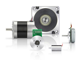
What is the significance of back EMF (electromotive force) in DC motor performance?
The significance of back EMF (electromotive force) in DC motor performance is crucial to understanding the behavior and operation of DC motors. Back EMF is an inherent characteristic of DC motors and plays a pivotal role in their efficiency, speed regulation, and overall performance. Here’s a detailed explanation of the significance of back EMF in DC motor performance:
When a DC motor operates, it generates a voltage known as back EMF or counter electromotive force. This voltage opposes the applied voltage and is caused by the rotation of the motor’s armature within the magnetic field. The back EMF is directly proportional to the rotational speed of the motor.
The significance of back EMF can be understood through the following aspects:
1. Speed Regulation:
Back EMF is crucial for regulating the speed of a DC motor. As the motor rotates faster, the back EMF increases, which reduces the effective voltage across the motor’s armature. Consequently, the armature current decreases, limiting the motor’s speed. This self-regulating characteristic helps maintain a relatively constant speed under varying load conditions. It allows the motor to deliver the required torque while preventing excessive speed that can potentially damage the motor or the driven equipment.
2. Efficiency:
Back EMF plays a significant role in the efficiency of a DC motor. When the motor is loaded and drawing current, the power supplied to the motor is the product of the armature current and the applied voltage. However, the electrical power converted into mechanical power is reduced by the power consumed by the back EMF. The back EMF represents the energy returned to the power supply as the motor generates its own voltage. By reducing the effective voltage across the motor, it helps minimize power losses due to electrical resistance and improves the overall efficiency of the motor.
3. Motor Protection:
The presence of back EMF also provides a level of protection to the motor. When a DC motor is operating and the load on the motor suddenly decreases, such as when the driven equipment is disconnected, the motor’s speed can increase rapidly. This increase in speed leads to a higher back EMF, which reduces the armature current and prevents excessive current flow. By limiting the current, the back EMF helps protect the motor from overloading and potential damage.
4. Voltage Regulation:
Back EMF affects the voltage regulation in a DC motor. When the motor is operating, the back EMF opposes the applied voltage. As the motor load increases, the voltage drop across the armature resistance and other internal losses also increase. The back EMF helps compensate for these voltage drops, ensuring that the motor receives an adequate voltage to maintain its performance and torque output.
5. Control and Dynamic Response:
Back EMF provides valuable information for motor control and dynamic response. By measuring the back EMF voltage, the rotational speed of the motor can be estimated, allowing for precise speed control and feedback. This information is crucial for applications that require accurate speed regulation, such as robotics or industrial automation.
In summary, the significance of back EMF in DC motor performance cannot be overstated. It influences speed regulation, efficiency, motor protection, voltage regulation, and control capabilities. By understanding and utilizing the inherent characteristics of back EMF, engineers can design and optimize DC motor systems for various applications, ensuring reliable and efficient operation.

How does the size and power rating of a DC motor affect its suitability for different tasks?
The size and power rating of a DC (Direct Current) motor play crucial roles in determining its suitability for different tasks and applications. The size and power rating directly impact the motor’s performance characteristics, including its torque output, speed range, efficiency, and overall capabilities. Here’s a detailed explanation of how the size and power rating of a DC motor affect its suitability for different tasks:
Size of DC Motor:
The size of a DC motor refers to its physical dimensions, including its diameter, length, and overall volume. The size of the motor influences its ability to fit into specific spaces or applications with space constraints. Here are some key considerations regarding the size of a DC motor:
1. Space Limitations: In applications where space is limited, such as small robotic systems or compact machinery, smaller-sized DC motors are preferred. These motors provide a more convenient and efficient integration into the overall system design.
2. Weight Constraints: Certain applications, such as drones or lightweight robots, may have strict weight limitations. Smaller-sized DC motors are generally lighter, making them more suitable for weight-sensitive tasks where minimizing the overall system weight is essential.
3. Cooling and Heat Dissipation: The size of a DC motor can impact its ability to dissipate heat generated during operation. Smaller-sized motors may have less surface area for heat dissipation, which can lead to increased operating temperatures. In contrast, larger-sized motors typically have better heat dissipation capabilities, allowing for sustained operation under heavy loads or in high-temperature environments.
Power Rating of DC Motor:
The power rating of a DC motor refers to the maximum power it can deliver or the power it consumes during operation. The power rating determines the motor’s capacity to perform work and influences its performance characteristics. Here are some key considerations regarding the power rating of a DC motor:
1. Torque Output: The power rating of a DC motor is directly related to its torque output. Higher power-rated motors generally provide higher torque, allowing them to handle more demanding tasks or applications that require greater force or load capacity. For example, heavy-duty industrial machinery or electric vehicles often require DC motors with higher power ratings to generate sufficient torque for their intended tasks.
2. Speed Range: The power rating of a DC motor affects its speed range capabilities. Motors with higher power ratings can typically achieve higher speeds, making them suitable for applications that require rapid or high-speed operation. On the other hand, lower power-rated motors may have limited speed ranges, making them more suitable for applications that require slower or controlled movements.
3. Efficiency: The power rating of a DC motor can impact its efficiency. Higher power-rated motors tend to have better efficiency, meaning they can convert a larger proportion of electrical input power into mechanical output power. Increased efficiency is desirable in applications where energy efficiency or battery life is a critical factor, such as electric vehicles or portable devices.
4. Overload Capability: The power rating of a DC motor determines its ability to handle overloads or sudden changes in load conditions. Motors with higher power ratings generally have a greater overload capacity, allowing them to handle temporary load spikes without stalling or overheating. This characteristic is crucial in applications where intermittent or varying loads are common.
Overall, the size and power rating of a DC motor are important factors in determining its suitability for different tasks. Smaller-sized motors are advantageous in space-constrained or weight-sensitive applications, while larger-sized motors offer better heat dissipation and can handle heavier loads. Higher power-rated motors provide greater torque, speed range, efficiency, and overload capability, making them suitable for more demanding tasks. It is crucial to carefully consider the specific requirements of the application and choose a DC motor size and power rating that aligns with those requirements to ensure optimal performance and reliability.
editor by CX 2024-02-07
China Good quality CHINAMFG 8 Inch BLDC Non-Gear Wheel Motor with Electric Brake vacuum pump oil near me
Product Description
What is hub motor?
The wheel hub motor (also called wheel motor, wheel hub drive, hub motor or in-wheel motor) is an electric motor that is incorporated into the hub of a wheel and drives it directly
Parameter for 8 inch hub motors
| Place of Origin | ZheJiang , China (Mainland) |
| Certification | CE |
| Commutation | Brushless |
| Continuous Current(A) | 1.3-12.4A |
| Efficiency | IE 4 |
| Noise | 55db |
| Motor type | Brushless DC Motor |
| Usage | Home Appliance, robotics, electric scooter, e-bike, etc. |
| Speed(RPM) | Max 1300(r/min) |
| Voltage | DC 24V/36V/48V |
| Power | MAX:400W |
| Speed | MAX:28-35km/h |
| Diameter with tire | 200mm |
| Brake | ebs brake |
| Tire | solid rubber tire |
| Weight | 3.5KG with tire |
| Cable | 3 motor phase , 5 hall sensor |
| Color | black |
Accessories
We have motor from min 3 inch(70mm) to max 15 inch (380mm), all waterproof and low noise, high quality with good price
We provide both single shaft and double shaft for all motors
We also provide motor built-in 1571ppr incremental encoder
FAQ
1. Factory or trader?
We are factory, the source of the supply chain.
2. Hub motor Delivery time?
Sample: 5 days. Bulk order: 7-25 days.
3. Why choose us?
* Factory Price & 24/7 after-sale services.
* 3 more quality test before products leave factory.
* Long life, durable and multi-application.
* Self Protection system avoids damage when overloaded or abruptly stoped.
* High efficiency and high torque available in small diameter.
* All products are made according to ISO 9001, CE, ROHS, CCC, UL and GS requirements.
/* March 10, 2571 17:59:20 */!function(){function s(e,r){var a,o={};try{e&&e.split(“,”).forEach(function(e,t){e&&(a=e.match(/(.*?):(.*)$/))&&1
| Application: | Universal, Industrial, Household Appliances, Car, Power Tools, Scooter |
|---|---|
| Operating Speed: | High Speed |
| Excitation Mode: | Compound |
| Function: | Control, Driving |
| Casing Protection: | Protection Type |
| Number of Poles: | 10 |
| Samples: |
US$ 75/Piece
1 Piece(Min.Order) | |
|---|
| Customization: |
Available
|
|
|---|

Can gear motors be used in robotics, and if so, what are some notable applications?
Yes, gear motors are widely used in robotics due to their ability to provide torque, precise control, and compact size. They play a crucial role in various robotic applications, enabling the movement, manipulation, and control of robotic systems. Here are some notable applications of gear motors in robotics:
1. Robotic Arm Manipulation:
Gear motors are commonly used in robotic arms to provide precise and controlled movement. They enable the articulation of the arm’s joints, allowing the robot to reach different positions and orientations. Gear motors with high torque capabilities are essential for lifting, rotating, and manipulating objects with varying weights and sizes.
2. Mobile Robots:
Gear motors are employed in mobile robots, including wheeled robots and legged robots, to drive their locomotion. They provide the necessary torque and control for the robot to move, turn, and navigate in different environments. Gear motors with appropriate gear ratios ensure the robot’s mobility, stability, and maneuverability.
3. Robotic Grippers and End Effectors:
Gear motors are used in robotic grippers and end effectors to control the opening, closing, and gripping force. By integrating gear motors into the gripper mechanism, robots can grasp and manipulate objects of various shapes, sizes, and weights. The gear motors enable precise control over the gripping action, allowing the robot to handle delicate or fragile objects with care.
4. Autonomous Drones and UAVs:
Gear motors are utilized in the propulsion systems of autonomous drones and unmanned aerial vehicles (UAVs). They drive the propellers or rotors, providing the necessary thrust and control for the drone’s flight. Gear motors with high power-to-weight ratios, efficient energy conversion, and precise speed control are crucial for achieving stable and maneuverable flight in drones.
5. Humanoid Robots:
Gear motors are integral to the movement and functionality of humanoid robots. They are used in robotic joints, such as hips, knees, and shoulders, to enable human-like movements. Gear motors with appropriate torque and speed capabilities allow humanoid robots to walk, run, climb stairs, and perform complex motions resembling human actions.
6. Robotic Exoskeletons:
Gear motors play a vital role in robotic exoskeletons, which are wearable robotic devices designed to augment human strength and assist in physical tasks. Gear motors are used in the exoskeleton’s joints and actuators, providing the necessary torque and control to enhance human abilities. They enable users to perform tasks with reduced effort, assist in rehabilitation, or provide support in physically demanding environments.
These are just a few notable applications of gear motors in robotics. Their versatility, torque capabilities, precise control, and compact size make them indispensable components in various robotic systems. Gear motors enable robots to perform complex tasks, move with agility, interact with the environment, and assist humans in a wide range of applications, from industrial automation to healthcare and exploration.
Can you explain the role of backlash in gear motors and how it’s managed in design?
Backlash plays a significant role in gear motors and is an important consideration in their design and operation. Backlash refers to the slight clearance or play between the teeth of gears in a gear system. It affects the precision, accuracy, and responsiveness of the gear motor. Here’s an explanation of the role of backlash in gear motors and how it is managed in design:
1. Role of Backlash:
Backlash in gear motors can have both positive and negative effects:
- Compensation for Misalignment: Backlash can help compensate for minor misalignments between gears, shafts, or the load. It allows a small amount of movement before engaging the next set of teeth, reducing the risk of damage due to misalignment. This can be particularly beneficial in applications where precise alignment is challenging or subject to variations.
- Negative Impact on Accuracy and Responsiveness: Backlash can introduce a delay or “dead zone” in the motion transmission. When changing the direction of rotation or reversing the load, the gear teeth must first overcome the clearance or play before engaging in the opposite direction. This delay can reduce the overall accuracy, responsiveness, and repeatability of the gear motor, especially in applications that require precise positioning or rapid changes in direction or speed.
2. Managing Backlash in Design:
Designers employ various techniques to manage and minimize backlash in gear motors:
- Tight Manufacturing Tolerances: Proper manufacturing techniques and tight tolerances can help minimize backlash. Precision machining and quality control during the production of gears and gear components ensure closer tolerances, reducing the amount of play between gear teeth.
- Preload or Pre-tensioning: Applying a preload or pre-tensioning force to the gear system can help reduce backlash. This technique involves introducing an initial force or tension that eliminates the clearance between gear teeth. It ensures immediate contact and engagement of the gear teeth, minimizing the dead zone and improving the overall responsiveness and accuracy of the gear motor.
- Anti-Backlash Gears: Anti-backlash gears are designed specifically to minimize or eliminate backlash. They typically feature modifications to the gear tooth profile, such as modified tooth shapes or special tooth arrangements, to reduce clearance. Anti-backlash gears can be used in gear motor designs to improve precision and minimize the effects of backlash.
- Backlash Compensation: In some cases, backlash compensation techniques can be employed. These techniques involve monitoring the position or movement of the load and applying control algorithms to compensate for the backlash. By accounting for the clearance and adjusting the control signals accordingly, the effects of backlash can be mitigated, improving accuracy and responsiveness.
3. Application-Specific Considerations:
The management of backlash in gear motors should be tailored to the specific application requirements:
- Positioning Accuracy: Applications that require precise positioning, such as robotics or CNC machines, may require tighter backlash control to ensure accurate and repeatable movements.
- Dynamic Response: Applications that involve rapid changes in direction or speed, such as high-speed automation or servo control systems, may require reduced backlash to maintain responsiveness and minimize overshoot or lag.
- Load Characteristics: The nature of the load and its impact on the gear system should be considered. Heavy loads or applications with significant inertial forces may require additional backlash management techniques to maintain stability and accuracy.
In summary, backlash in gear motors can affect precision, accuracy, and responsiveness. While it can compensate for misalignments, backlash may introduce delays and reduce the overall performance of the gear motor. Designers manage backlash through tight manufacturing tolerances, preload techniques, anti-backlash gears, and backlash compensation methods. The management of backlash depends on the specific application requirements, considering factors such as positioning accuracy, dynamic response, and load characteristics.

How does the gearing mechanism in a gear motor contribute to torque and speed control?
The gearing mechanism in a gear motor plays a crucial role in controlling torque and speed. By utilizing different gear ratios and configurations, the gearing mechanism allows for precise manipulation of these parameters. Here’s a detailed explanation of how the gearing mechanism contributes to torque and speed control in a gear motor:
The gearing mechanism consists of multiple gears with varying sizes, tooth configurations, and arrangements. Each gear in the system engages with another gear, creating a mechanical connection. When the motor rotates, it drives the rotation of the first gear, which then transfers the motion to subsequent gears, ultimately resulting in the output shaft’s rotation.
Torque Control:
The gearing mechanism in a gear motor enables torque control through the principle of mechanical advantage. The gear system utilizes gears with different numbers of teeth, known as gear ratio, to adjust the torque output. When a smaller gear (pinion) engages with a larger gear (gear), the pinion rotates faster than the gear but exerts more force or torque. This results in torque amplification, allowing the gear motor to deliver higher torque at the output shaft while reducing the rotational speed. Conversely, if a larger gear engages with a smaller gear, torque reduction occurs, resulting in higher rotational speed at the output shaft.
By selecting the appropriate gear ratio, the gearing mechanism effectively adjusts the torque output of the gear motor to match the requirements of the application. This torque control capability is essential in applications that demand high torque for heavy lifting or overcoming resistance, as well as applications that require lower torque but higher rotational speed.
Speed Control:
The gearing mechanism also contributes to speed control in a gear motor. The gear ratio determines the relationship between the rotational speed of the input shaft (driven by the motor) and the output shaft. When a gear motor has a higher gear ratio (more teeth on the driven gear compared to the driving gear), it reduces the output speed while increasing the torque. Conversely, a lower gear ratio increases the output speed while reducing the torque.
By choosing the appropriate gear ratio, the gearing mechanism allows for precise speed control in a gear motor. This is particularly useful in applications that require specific speed ranges or variations, such as conveyor systems, robotic movements, or machinery that needs to operate at different speeds for different tasks. The speed control capability of the gearing mechanism enables the gear motor to match the desired speed requirements of the application accurately.
In summary, the gearing mechanism in a gear motor contributes to torque and speed control by utilizing different gear ratios and configurations. It enables torque amplification or reduction, depending on the gear arrangement, allowing the gear motor to deliver the required torque output. Additionally, the gear ratio also determines the relationship between the rotational speed of the input and output shafts, providing precise speed control. These torque and speed control capabilities make gear motors versatile and suitable for a wide range of applications in various industries.
editor by CX 2024-01-25
China manufacturer 12V 24V 36V 48V 310V Electric DC Brushless DC Geared Servo Motor/ BLDC Motor with Encoder / Planetary Gearbox / Brake wholesaler
Product Description
12V 24V 36V 48V 310V Electric DC Brushless DC Servo Motor/ BLDC Motor with Encoder / Planetary Gearbox / Brake
Product Description
Product Name: Brushless DC Motor
Number of Phase: 3 Phase
Number of Poles: 4 Poles /8 Poles /10 Poles
Rated Voltage: 12v /24v /36v /48v /310v
Rated Speed: 3000rpm /4000rpm /or customized
Rated Torque: Customized
Rated Current: Customized
Rated Power: 23w~2500W
Jkongmotor has a wide range of micro motor production lines in the industry, including Stepper Motor, DC Servo Motor, AC Motor, Brushless Motor, Planetary Gear Motor, Planetary Gearbox etc. Through technical innovation and customization, we help you create outstanding application systems and provide flexible solutions for various industrial automation situations.
42mm 24V Brushless DC Motor Parameters:
| Specification | Unit | Model | |||
| JK42BLS01 | JK42BLS02 | JK42BLS03 | JK42BLS04 | ||
| Number Of Phase | Phase | 3 | |||
| Number Of Poles | Poles | 8 | |||
| Rated Voltage | VDC | 24 | |||
| Rated Speed | Rpm | 4000 | |||
| Rated Torque | N.m | 0.0625 | 0.125 | 0.185 | 0.25 |
| Peak Current | Amps | 1.8 | 3.3 | 4.8 | 6.3 |
| Rated Power | W | 26 | 52.5 | 77.5 | 105 |
| Peak Torque | N.m | 0.19 | 0.38 | 0.56 | 0.75 |
| Peak Current | Amps | 5.4 | 10.6 | 15.5 | 20 |
| Back E.M.F | V/Krpm | 4.1 | 4.2 | 4.3 | 4.3 |
| Torque Constant | N.m/A | 0.039 | 0.04 | 0.041 | 0.041 |
| Rotor Inertia | g.cm2 | 24 | 48 | 72 | 96 |
| Body Length | mm | ||||
| Weight | Kg | ||||
| Sensor | Honeywell | ||||
| Insulation Class | B | ||||
| Degree of Protection | IP30 | ||||
| Storage Temperature | -25~+70ºC | ||||
| Operating Temperature | -15~+50ºC | ||||
| Working Humidity | 85% RH or below (no condensation) | ||||
| Working Environment | Outdoor (no direct sunlight), no corrosive gas, no flammable gas, no oil mist, no dust | ||||
| Altitude | 1000 CHINAMFG or less | ||||
57mm 36V Brushless DC Motor Parameters:
| Specification | Unit | Model | ||||
| JK57BLS005 | JK57BLS01 | JK57BLS02 | JK57BLS03 | JK57BLS04 | ||
| Number Of Phase | Phase | 3 | ||||
| Number Of Poles | Poles | 4 | ||||
| Rated Voltage | VDC | 36 | ||||
| Rated Speed | Rpm | 4000 | ||||
| Rated Torque | N.m | 0.055 | 0.11 | 0.22 | 0.33 | 0.44 |
| Rated Current | Amps | 1.2 | 2 | 3.6 | 5.3 | 6.8 |
| Rated Power | W | 23 | 46 | 92 | 138 | 184 |
| Peak Torque | N.m | 0.16 | 0.33 | 0.66 | 1 | 1.32 |
| Peak Current | Amps | 3.5 | 6.8 | 11.5 | 15.5 | 20.5 |
| Back E.M.F | V/Krpm | 7.8 | 7.7 | 7.4 | 7.3 | 7.1 |
| Torque Constant | N.m/A | 0.074 | 0.073 | 0.07 | 0.07 | 0.068 |
| Rotor Inertia | g.cm2 | 30 | 75 | 119 | 173 | 230 |
| Body Length | mm | 37 | 47 | 67 | 87 | 107 |
| Weight | Kg | 0.33 | 0.44 | 0.75 | 1 | 1.25 |
| Sensor | Honeywell | |||||
| Insulation Class | B | |||||
| Degree of Protection | IP30 | |||||
| Storage Temperature | -25~+70ºC | |||||
| Operating Temperature | -15~+50ºC | |||||
| Working Humidity | 85% RH or below (no condensation) | |||||
| Working Environment | Outdoor (no direct sunlight), no corrosive gas, no flammable gas, no oil mist, no dust | |||||
| Altitude | 1000 CHINAMFG or less | |||||
60mm 48V Brushless DC Motor Parameters:
| Specification | Unit | Model | |||
| JK60BLS01 | JK60BLS02 | JK60BLS03 | JK60BLS04 | ||
| Number Of Phase | Phase | 3 | |||
| Number Of Poles | Poles | 8 | |||
| Rated Voltage | VDC | 48 | |||
| Rated Speed | Rpm | 3000 | |||
| Rated Torque | N.m | 0.3 | 0.6 | 0.9 | 1.2 |
| Rated Current | Amps | 2.8 | 5.2 | 7.5 | 9.5 |
| Rated Power | W | 94 | 188 | 283 | 377 |
| Peak Torque | N.m | 0.9 | 1.8 | 2.7 | 3.6 |
| Peak Current | Amps | 8.4 | 15.6 | 22.5 | 28.5 |
| Back E.M.F | V/Krpm | 12.1 | 12.6 | 12.4 | 13.3 |
| Torque Constant | N.m/A | 0.116 | 0.12 | 0.118 | 0.127 |
| Rotor Inertia | kg.cm2 | 0.24 | 0.48 | 0.72 | 0.96 |
| Body Length | mm | 78 | 99 | 120 | 141 |
| Weight | Kg | 0.85 | 1.25 | 1.65 | 2.05 |
| Sensor | Honeywell | ||||
| Insulation Class | B | ||||
| Degree of Protection | IP30 | ||||
| Storage Temperature | -25~+70ºC | ||||
| Operating Temperature | -15~+50ºC | ||||
| Working Humidity | 85% RH or below (no condensation) | ||||
| Working Environment | Outdoor (no direct sunlight), no corrosive gas, no flammable gas, no oil mist, no dust | ||||
| Altitude | 1000 CHINAMFG or less | ||||
80mm 48V BLDC Motor Parameters:
| Specification | Unit | Model | |||
| JK80BLS01 | JK80BLS02 | JK80BLS03 | JK80BLS04 | ||
| Number Of Phase | Phase | 3 | |||
| Number Of Poles | Poles | 4 | |||
| Rated Voltage | VDC | 48 | |||
| Rated Speed | Rpm | 3000 | |||
| Rated Torque | N.m | 0.35 | 0.7 | 1.05 | 1.4 |
| Rated Current | Amps | 3 | 5.5 | 8 | 10.5 |
| Rated Power | W | 110 | 220 | 330 | 440 |
| Peak Torque | N.m | 1.05 | 2.1 | 3.15 | 4.2 |
| Peak Current | Amps | 9 | 16.5 | 24 | 31.5 |
| Back E.M.F | V/Krpm | 13.5 | 13.3 | 13.1 | 13 |
| Torque Constant | N.m/A | 0.13 | 0.127 | 0.126 | 0.124 |
| Rotor Inertia | g.cm2 | 210 | 420 | 630 | 840 |
| Body Length | mm | 78 | 98 | 118 | 138 |
| Weight | Kg | 1.4 | 2 | 2.6 | 3.2 |
| Sensor | Honeywell | ||||
| Insulation Class | B | ||||
| Degree of Protection | IP30 | ||||
| Storage Temperature | -25~+70ºC | ||||
| Operating Temperature | -15~+50ºC | ||||
| Working Humidity | 85% RH or below (no condensation) | ||||
| Working Environment | Outdoor (no direct sunlight), no corrosive gas, no flammable gas, no oil mist, no dust | ||||
| Altitude | 1000 CHINAMFG or less | ||||
86mm 48V Dc Brushless Motor Parameters:
| Specification | Unit | Model | ||||
| JK86BLS58 | JK86BLS71 | JK86BLS84 | JK86BLS98 | JK86BLS125 | ||
| Number Of Phase | Phase | 3 | ||||
| Number Of Poles | Poles | 8 | ||||
| Rated Voltage | VDC | 48 | ||||
| Rated Speed | Rpm | 3000 | ||||
| Rated Torque | N.m | 0.35 | 0.7 | 1.05 | 1.4 | 2.1 |
| Rated Current | Amps | 3 | 6.3 | 9 | 11.5 | 18 |
| Rated Power | W | 110 | 220 | 330 | 440 | 660 |
| Peak Torque | N.m | 1.05 | 2.1 | 3.15 | 4.2 | 6.3 |
| Peak Current | Amps | 9 | 19 | 27 | 35 | 54 |
| Back E.M.F | V/Krpm | 13.7 | 13 | 13.5 | 13.7 | 13.5 |
| Torque Constant | N.m/A | 0.13 | 0.12 | 0.13 | 0.13 | 0.13 |
| Rotor Inertia | g.cm2 | 400 | 800 | 1200 | 1600 | 2400 |
| Body Length | mm | 71 | 84.5 | 98 | 111.5 | 138.5 |
| Weight | Kg | 1.5 | 1.9 | 2.3 | 2.7 | 4 |
| Sensor | Honeywell | |||||
| Insulation Class | B | |||||
| Degree of Protection | IP30 | |||||
| Storage Temperature | -25~+70ºC | |||||
| Operating Temperature | -15~+50ºC | |||||
| Working Humidity | 85% RH or below (no condensation) | |||||
| Working Environment | Outdoor (no direct sunlight), no corrosive gas, no flammable gas, no oil mist, no dust | |||||
| Altitude | 1000 CHINAMFG or less | |||||
110mm 310V Brushless Motor Parameters:
| Specification | Unit | Model | |||
| JK110BLS050 | JK110BLS75 | JK110BLS100 | JK110BLS125 | ||
| Number Of Phase | Phase | 3 | |||
| Number Of Poles | Poles | 8 | |||
| Rated Voltage | VDC | 310 | |||
| Rated Speed | Rpm | 3400 | |||
| Rated Torque | N.m | 2.38 | 3.3 | 5 | 6.6 |
| Rated Current | Amps | 0.5 | 0.6 | 0.8 | 1 |
| Rated Power | KW | 0.75 | 1.03 | 1.57 | 2.07 |
| Back E.M.F | V/Krpm | 91.1 | 91.1 | 91.1 | 88.6 |
| Torque Constant | N.m/A | 0.87 | 0.87 | 0.87 | 0.845 |
| Body Length | mm | 130 | 155 | 180 | 205 |
| Sensor | Honeywell | ||||
| Insulation Class | H | ||||
Stepping Motor Customized
Planetary Gearbox Type:
Detailed Photos
Cnc Motor Kits Brushless dc Motor with Brake
Brushless Dc Motor with Planetary Gearbox Bldc Motor with Encoder
Brushless Dc Motor Brushed Dc Motor Hybrid Stepper Motor
Company Profile
HangZhou CHINAMFG Co., Ltd was a high technology industry zone in HangZhou, china. Our products used in many kinds of machines, such as 3d printer CNC machine, medical equipment, weaving printing equipments and so on.
JKONGMOTOR warmly welcome ‘OEM’ & ‘ODM’ cooperations and other companies to establish long-term cooperation with us.
Company spirit of sincere and good reputation, won the recognition and support of the broad masses of customers, at the same time with the domestic and foreign suppliers close community of interests, the company entered the stage of stage of benign development, laying a CHINAMFG foundation for the strategic goal of realizing only really the sustainable development of the company.
Equipments Show:
Production Flow:
Package:
Certification:
| Application: | Universal, Industrial, Household Appliances, Car, Power Tools |
|---|---|
| Operating Speed: | Adjust Speed |
| Excitation Mode: | Compound |
| Samples: |
US$ 30/Piece
1 Piece(Min.Order) | Order Sample need to confirm the cost with seller
|
|---|
| Customization: |
Available
|
|
|---|
.shipping-cost-tm .tm-status-off{background: none;padding:0;color: #1470cc}
|
Shipping Cost:
Estimated freight per unit. |
about shipping cost and estimated delivery time. |
|---|
| Payment Method: |
|
|---|---|
|
Initial Payment Full Payment |
| Currency: | US$ |
|---|
| Return&refunds: | You can apply for a refund up to 30 days after receipt of the products. |
|---|

What is a DC motor, and how does it differ from other types of electric motors?
A DC (Direct Current) motor is an electric motor that converts electrical energy into mechanical motion. It operates based on the principle of electromagnetic induction and the interaction between current-carrying conductors and magnetic fields. DC motors are widely used in various applications due to their simplicity, controllability, and versatility. Here’s a detailed explanation of what a DC motor is and how it differs from other types of electric motors:
1. Basic Operation:
In a DC motor, electrical energy is supplied to the motor’s armature through a DC power source, typically a battery or a rectified power supply. The armature consists of multiple coils or windings that are evenly spaced around the motor’s rotor. The rotor is a cylindrical core with a shaft that rotates when the motor is energized. When current flows through the armature windings, it creates a magnetic field that interacts with the fixed magnetic field produced by the motor’s stator. This interaction generates a torque, causing the rotor to rotate.
2. Commutation:
DC motors employ a commutator and brushes for the conversion of electrical energy and the rotation of the rotor. The commutator consists of a segmented cylindrical ring attached to the rotor shaft, and the brushes are stationary conductive contacts that make contact with the commutator segments. As the rotor spins, the brushes maintain contact with the commutator segments, periodically reversing the direction of the current flow in the armature windings. This reversal of current flow in the armature windings ensures continuous rotation of the rotor in the same direction.
3. Types of DC Motors:
DC motors can be classified into different types based on their construction and the method of field excitation. The two main types are:
- Brushed DC Motors: Brushed DC motors have a mechanical commutator and brushes to switch the current direction in the armature windings. These motors are relatively simple, cost-effective, and offer good torque characteristics. However, the commutator and brushes require regular maintenance and can generate electrical noise and brush wear debris.
- Brushless DC Motors (BLDC): Brushless DC motors, also known as electronically commutated motors (ECMs), use electronic circuits and sensors to control the current flow in the motor windings. They eliminate the need for brushes and commutators, resulting in reduced maintenance and improved reliability. BLDC motors offer higher efficiency, smoother operation, and better speed control compared to brushed DC motors.
4. Speed Control:
DC motors provide excellent speed control capabilities. By adjusting the voltage applied to the motor, the speed of the DC motor can be regulated. Lowering the voltage reduces the motor’s speed, while increasing the voltage increases the speed. This feature makes DC motors suitable for applications that require precise speed control, such as robotics, conveyor systems, and electric vehicles.
5. Advantages and Disadvantages:
DC motors have several advantages, including:
- Simple construction and easy maintenance (for brushed DC motors).
- High starting torque.
- Precise speed control.
- Good controllability over a wide range of loads.
However, DC motors also have some limitations, such as:
- Brushed DC motors require periodic maintenance and have limited brush life.
- Brushed DC motors can generate electrical noise.
- Brushless DC motors are often more expensive compared to brushed DC motors.
6. Differences from Other Electric Motors:
DC motors differ from other types of electric motors, such as AC (Alternating Current) motors, in several ways:
- Power Source: DC motors require a DC power source, while AC motors operate from an AC power supply.
- Speed Control: DC motors offer precise speed control by adjusting the applied voltage, whereas AC motors typically rely on frequency control for speed regulation.
- Construction: DC motors use a commutator and brushes (in brushed DC motors) or electronic commutation (in brushless DC motors), while AC motors do not require commutation.
- Starting Torque: DC motors typically provide higher starting torque compared to AC motors.
Overall, DC motors are versatile and widely used in various applications due to their controllability, speed regulation capabilities, and simplicity. The advancements inpower electronics and motor control technologies have further enhanced the performance and efficiency of DC motors, making them a popular choice in many industries.
What role does commutation play in the operation of a DC motor?
In the operation of a DC (Direct Current) motor, commutation plays a crucial role in ensuring the continuous rotation of the motor and the conversion of electrical energy into mechanical motion. It is the process by which the direction of the current in the armature winding is periodically reversed to maintain a constant torque and facilitate the rotation of the motor. Here’s a detailed explanation of the role of commutation in the operation of a DC motor:
Commutation is necessary in a DC motor because the magnetic field generated by the armature winding needs to be constantly aligned with the stator’s magnetic field for efficient torque production. The stator of a DC motor typically consists of permanent magnets or electromagnets that create a fixed magnetic field. The armature winding, located on the rotor, produces a magnetic field that interacts with the stator’s field to generate torque.
The commutation process is achieved through the use of a commutator and brushes. The commutator is a cylindrical ring with multiple segments, while the brushes are conductive contacts that make physical contact with the commutator segments. The armature winding is connected to the commutator, and as the rotor spins, the brushes maintain contact with different segments.
As the rotor rotates, the commutator and brushes ensure that the direction of the current in the armature winding is reversed at specific intervals. This reversal of current flow is necessary to maintain a consistent torque in the same rotational direction. Without commutation, the torque generated by the motor would fluctuate in both magnitude and direction, leading to instability and erratic motor behavior.
The commutation process involves two stages: mechanical commutation and electrical commutation.
1. Mechanical Commutation: As the rotor rotates, the brushes make contact with different segments of the commutator. The segments are insulated from each other to prevent short circuits. When the brushes move from one segment to another, the current flowing through the armature winding is switched to a different coil or set of coils. This mechanical switching ensures that the magnetic fields produced by the winding are properly aligned with the stator’s field, resulting in continuous torque production.
2. Electrical Commutation: The reversal of current in the armature winding is achieved through electrical commutation. When the brushes make contact with a new commutator segment, the current flow in the winding is redirected to maintain the desired torque direction. The timing and sequence of the current reversal are critical to ensure smooth and efficient motor operation.
The commutation process in a DC motor is a dynamic and continuous operation. It allows for the conversion of electrical energy into mechanical motion by providing a consistent torque output. The efficiency and performance of the motor are greatly influenced by the quality and effectiveness of the commutation process.
In summary, commutation plays a vital role in the operation of a DC motor by ensuring the continuous rotation of the motor and the production of consistent torque. It involves the mechanical and electrical switching of the current direction in the armature winding, facilitated by the commutator and brushes.
How does the size and power rating of a DC motor affect its suitability for different tasks?
The size and power rating of a DC (Direct Current) motor play crucial roles in determining its suitability for different tasks and applications. The size and power rating directly impact the motor’s performance characteristics, including its torque output, speed range, efficiency, and overall capabilities. Here’s a detailed explanation of how the size and power rating of a DC motor affect its suitability for different tasks:
Size of DC Motor:
The size of a DC motor refers to its physical dimensions, including its diameter, length, and overall volume. The size of the motor influences its ability to fit into specific spaces or applications with space constraints. Here are some key considerations regarding the size of a DC motor:
1. Space Limitations: In applications where space is limited, such as small robotic systems or compact machinery, smaller-sized DC motors are preferred. These motors provide a more convenient and efficient integration into the overall system design.
2. Weight Constraints: Certain applications, such as drones or lightweight robots, may have strict weight limitations. Smaller-sized DC motors are generally lighter, making them more suitable for weight-sensitive tasks where minimizing the overall system weight is essential.
3. Cooling and Heat Dissipation: The size of a DC motor can impact its ability to dissipate heat generated during operation. Smaller-sized motors may have less surface area for heat dissipation, which can lead to increased operating temperatures. In contrast, larger-sized motors typically have better heat dissipation capabilities, allowing for sustained operation under heavy loads or in high-temperature environments.
Power Rating of DC Motor:
The power rating of a DC motor refers to the maximum power it can deliver or the power it consumes during operation. The power rating determines the motor’s capacity to perform work and influences its performance characteristics. Here are some key considerations regarding the power rating of a DC motor:
1. Torque Output: The power rating of a DC motor is directly related to its torque output. Higher power-rated motors generally provide higher torque, allowing them to handle more demanding tasks or applications that require greater force or load capacity. For example, heavy-duty industrial machinery or electric vehicles often require DC motors with higher power ratings to generate sufficient torque for their intended tasks.
2. Speed Range: The power rating of a DC motor affects its speed range capabilities. Motors with higher power ratings can typically achieve higher speeds, making them suitable for applications that require rapid or high-speed operation. On the other hand, lower power-rated motors may have limited speed ranges, making them more suitable for applications that require slower or controlled movements.
3. Efficiency: The power rating of a DC motor can impact its efficiency. Higher power-rated motors tend to have better efficiency, meaning they can convert a larger proportion of electrical input power into mechanical output power. Increased efficiency is desirable in applications where energy efficiency or battery life is a critical factor, such as electric vehicles or portable devices.
4. Overload Capability: The power rating of a DC motor determines its ability to handle overloads or sudden changes in load conditions. Motors with higher power ratings generally have a greater overload capacity, allowing them to handle temporary load spikes without stalling or overheating. This characteristic is crucial in applications where intermittent or varying loads are common.
Overall, the size and power rating of a DC motor are important factors in determining its suitability for different tasks. Smaller-sized motors are advantageous in space-constrained or weight-sensitive applications, while larger-sized motors offer better heat dissipation and can handle heavier loads. Higher power-rated motors provide greater torque, speed range, efficiency, and overload capability, making them suitable for more demanding tasks. It is crucial to carefully consider the specific requirements of the application and choose a DC motor size and power rating that aligns with those requirements to ensure optimal performance and reliability.
editor by CX 2023-10-20
China MY1016 DC 24v 250w electric wheelchair motor with electromagnetic brake 75rpm 120rpm 160rpm mobility vehicle lawn mower dc motor with Hot selling
Warranty: twelve months
Model Amount: MY1016 wheelchair motor dc motor
Use: BOAT, Vehicle, Electric powered Bicycle, Fan, House Equipment, Cosmetic instrument, Sensible Residence
Type: Gear MOTOR
Torque: 30N.m
Development: Permanent Magnet
Commutation: Brush
Safeguard Attribute: IP54
Velocity(RPM): 75/one hundred twenty/160rpm
Continuous Recent(A): thirteen.4A
Effectiveness: IE 2
Merchandise Title: MY1016 electrical wheelchair motor dc motor
Software: Wheel Chair lawn mower
Voltage: 12V/24V
Electricity: 250W
Wire duration: more than 45mm
Motor sort: DC brush motor
Recent: thirteen.4A
Torque of brake: >=30N.m
Noise: Minimal Sound Level
Operate: Driven Products
Packaging Specifics: Standard export package for MY1016 electrical wheelchair motor dc motor
Port: ZheJiang , HangZhou, ZheJiang
DC 24V 250W seventy five/a hundred and twenty/160rpm dc brush motor wheelchair motor Merchandise Description Lower Pace DC 24V 250W BRUSH MOTOROutput speeds:75/120/a hundred and sixty rpm(pls validate according to your need)Single motor weight 3kg (with out brake) with brake type (3.5kg)Output shaft: diameter 17mm and duration 44mm (keyway sort)This variety motor is extensively employed for electrical wheelchair, 2KW .7KW V90 Servo Motor with Push Servo Motor with Push PROFINET Servo Motor -330Hz CECCC Carton Package deal 380V TT and also other electric powered instrument, like lawn mower or other electric powered car, atv or agv. . Parameters
| MY1016Z Wheelchair Motor | ||
| Voltage | 24V | |
| Electrical power | 250W | |
| Motor speed | 2400 / 3700 RPM | |
| No-load speed | 75rpm/ 120 rpm/160rpm | |
| Output speed | 75/a hundred and twenty/one hundred sixty rpm | |
| Rated torque | ≥45mm | |
| No-load recent | ≤ 4. A | |
| Rated recent | ≤13.7 / 14.8 A | |
| Functioning several hours | S2 : 60 | |
| Insulation class | E | |
| Reduction ratio | 23.2 : 1 | |
| Motor effectiveness | ≥ 70 / seventy six % | |
| Load capability | 100kg/pcs | |
| Software | wheelchair | |
Benefits of a Planetary Motor
If you’re looking for an affordable way to power a machine, consider purchasing a Planetary Motor. These units are designed to provide a massive range of gear reductions, and are capable of generating much higher torques and torque density than other types of drive systems. This article will explain why you should consider purchasing one for your needs. And we’ll also discuss the differences between a planetary and spur gear system, as well as how you can benefit from them.
planetary gears
Planetary gears in a motor are used to reduce the speed of rotation of the armature 8. The reduction ratio is determined by the structure of the planetary gear device. The output shaft 5 rotates through the device with the assistance of the ring gear 4. The ring gear 4 engages with the pinion 3 once the shaft is rotated to the engagement position. The transmission of rotational torque from the ring gear to the armature causes the motor to start.
The axial end surface of a planetary gear device has two circular grooves 21. The depressed portion is used to retain lubricant. This lubricant prevents foreign particles from entering the planetary gear space. This feature enables the planetary gear device to be compact and lightweight. The cylindrical portion also minimizes the mass inertia. In this way, the planetary gear device can be a good choice for a motor with limited space.
Because of their compact footprint, planetary gears are great for reducing heat. In addition, this design allows them to be cooled. If you need high speeds and sustained performance, you may want to consider using lubricants. The lubricants present a cooling effect and reduce noise and vibration. If you want to maximize the efficiency of your motor, invest in a planetary gear hub drivetrain.
The planetary gear head has an internal sun gear that drives the multiple outer gears. These gears mesh together with the outer ring that is fixed to the motor housing. In industrial applications, planetary gears are used with an increasing number of teeth. This distribution of power ensures higher efficiency and transmittable torque. There are many advantages of using a planetary gear motor. These advantages include:
planetary gearboxes
A planetary gearbox is a type of drivetrain in which the input and output shafts are connected with a planetary structure. A planetary gearset can have three main components: an input gear, a planetary output gear, and a stationary position. Different gears can be used to change the transmission ratios. The planetary structure arrangement gives the planetary gearset high rigidity and minimizes backlash. This high rigidity is crucial for quick start-stop cycles and rotational direction.
Planetary gears need to be lubricated regularly to prevent wear and tear. In addition, transmissions must be serviced regularly, which can include fluid changes. The gears in a planetary gearbox will wear out with time, and any problems should be repaired immediately. However, if the gears are damaged, or if they are faulty, a planetary gearbox manufacturer will repair it for free.
A planetary gearbox is typically a 2-speed design, but professional manufacturers can provide triple and single-speed sets. Planetary gearboxes are also compatible with hydraulic, electromagnetic, and dynamic braking systems. The first step to designing a planetary gearbox is defining your application and the desired outcome. Famous constructors use a consultative modeling approach, starting each project by studying machine torque and operating conditions.
As the planetary gearbox is a compact design, space is limited. Therefore, bearings need to be selected carefully. The compact needle roller bearings are the most common option, but they cannot tolerate large axial forces. Those that can handle high axial forces, such as worm gears, should opt for tapered roller bearings. So, what are the advantages and disadvantages of a helical gearbox?
planetary gear motors
When we think of planetary gear motors, we tend to think of large and powerful machines, but in fact, there are many smaller, more inexpensive versions of the same machine. These motors are often made of plastic, and can be as small as six millimeters in diameter. Unlike their larger counterparts, they have only one gear in the transmission, and are made with a small diameter and small number of teeth.
They are similar to the solar system, with the planets rotating around a sun gear. The planet pinions mesh with the ring gear inside the sun gear. All of these gears are connected by a planetary carrier, which is the output shaft of the gearbox. The ring gear and planetary carrier assembly are attached to each other through a series of joints. When power is applied to any of these members, the entire assembly will rotate.
Compared to other configurations, planetary gearmotors are more complicated. Their construction consists of a sun gear centered in the center and several smaller gears that mesh with the central sun gear. These gears are enclosed in a larger internal tooth gear. This design allows them to handle larger loads than conventional gear motors, as the load is distributed among several gears. This type of motor is typically more expensive than other configurations, but can withstand the higher-load requirements of some machines.
Because they are cylindrical in shape, planetary gear motors are incredibly versatile. They can be used in various applications, including automatic transmissions. They are also used in applications where high-precision and speed are necessary. Furthermore, the planetary gear motor is robust and is characterized by low vibrations. The advantages of using a planetary gear motor are vast and include:
planetary gears vs spur gears
A planetary motor uses multiple teeth to share the load of rotating parts. This gives planetary gears high stiffness and low backlash – often as low as one or two arc minutes. These characteristics are important for applications that undergo frequent start-stop cycles or rotational direction changes. This article discusses the benefits of planetary gears and how they differ from spur gears. You can watch the animation below for a clearer understanding of how they operate and how they differ from spur gears.
Planetary gears move in a periodic manner, with a relatively small meshing frequency. As the meshing frequency increases, the amplitude of the frequency also increases. The amplitude of this frequency is small at low clearance values, and increases dramatically at higher clearance levels. The amplitude of the frequency is higher when the clearance reaches 0.2-0.6. The amplitude increases rapidly, whereas wear increases slowly after the initial 0.2-0.6-inch-wide clearance.
In high-speed, high-torque applications, a planetary motor is more effective. It has multiple contact points for greater torque and higher speed. If you are not sure which type to choose, you can consult with an expert and design a custom gear. If you are unsure of what type of motor you need, contact Twirl Motor and ask for help choosing the right one for your application.
A planetary gear arrangement offers a number of advantages over traditional fixed-axis gear system designs. The compact size allows for lower loss of effectiveness, and the more planets in the gear system enhances the torque density and capacity. Another benefit of a planetary gear system is that it is much stronger and more durable than its spur-gear counterpart. Combined with its many advantages, a planetary gear arrangement offers a superior solution to your shifting needs.
planetary gearboxes as a compact alternative to pinion-and-gear reducers
While traditional pinion-and-gear reducer design is bulky and complex, planetary gearboxes are compact and flexible. They are suitable for many applications, especially where space and weight are issues, as well as torque and speed reduction. However, understanding their mechanism and working isn’t as simple as it sounds, so here are some of the key benefits of planetary gearing.
Planetary gearboxes work by using two planetary gears that rotate around their own axes. The sun gear is used as the input, while the planetary gears are connected via a casing. The ratio of these gears is -Ns/Np, with 24 teeth in the sun gear and -3/2 on the planet gear.
Unlike traditional pinion-and-gear reducer designs, planetary gearboxes are much smaller and less expensive. A planetary gearbox is about 50% smaller and weighs less than a pinion-and-gear reducer. The smaller gear floats on top of three large gears, minimizing the effects of vibration and ensuring consistent transmission over time.
Planetary gearboxes are a good alternative to pinion-and-gear drive systems because they are smaller, less complex and offer a higher reduction ratio. Their meshing arrangement is similar to the Milky Way, with the sun gear in the middle and two or more outer gears. They are connected by a carrier that sets their spacing and incorporates an output shaft.
Compared to pinion-and-gear reduces, planetary gearboxes offer higher speed reduction and torque capacity. As a result, planetary gearboxes are small and compact and are often preferred for space-constrained applications. But what about the high torque transfer? If you’re looking for a compact alt
editor by czh 2023-02-20